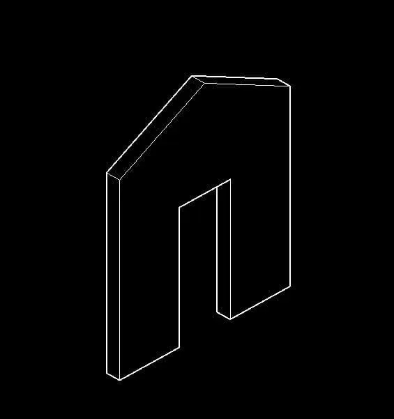
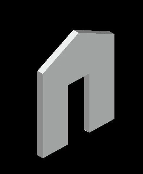
Creating various 3D Models like Furniture, Footing, Girder, Column drop with panel and Gable Wall in AutoCad
1. AIM
To create a 3D Furniture elements using the various commands in autoCAD.
INTRODUCTION BY 3D VIEW
- The process of creating a mathematical representation of any surface of an object in three dimensions by using special suftware.
- A 3D model can even be represented as a two dimensional image by using the 3d redering process.
- It enables the professional creation and edition of 2D geometry and 3D madels with solids,surfaces and objects.
PROCEDURE
- To create a new sheet from application of autoCAD.
- Go to the setting and to change the view of the page of drafting to3D modeling.
- Type"UN" to set the units of current format of measure.(feet and inches).
- Type"limits"to set the maximum dimension limits on the particular page.
- First we take to a 3d custom view.
- Type "REC" to create a rectangle with a dimension of 2'3"*3'0".
- And then we take a 3d custom view.
- Type"3D orbit" to view a 3d orbit view port in the current view port
- Then ,we take a all box dimension to create it from the origin point is (0,0,0).
- Next point we take to X direction of (@2'6",0,0)
- Type extrude to create a surface or solid of a 2D surface.
- Then we hAave to change the view of 2D wire ,Shaded,Conceptional,etc.
- Type ,3D FACE " for allows to generate 3D faces by identifying.
- To save the diagram to particular file.
RESULTS
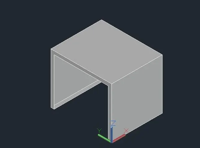
The diagram of 3D furniture elements is drawn as per dimensions using the software of auto.
2 .AIM
To create a 3D model of an isolated footings using the various commands in Auto CAD.
PROCEDURE
- To create a nmew sheet from application of autoCAD.
- Go to the setting and to change the view of the page from drafting to 3D modeling.
- Type"UN" to set the units of current format of measure.(feet and inches).
- Type"LIMITS" to set the maximum dimension limits on the particular page.
- First we take the top view of the page.
- Type "rec"to create a rectangle with a given dimensions.
- And then we take to a 3D custom view.
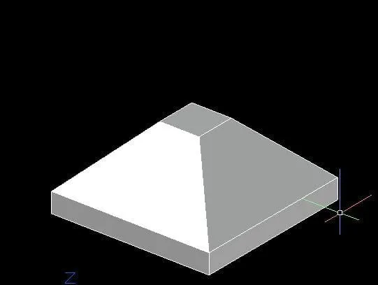
- The footnig dimension is 4'0"*4'0".
- The depth of footing is 6" and reduced to the depth of 2" and width is 1'0".
- COPY-this commands is used to selected objects from a given square to destination ,learning a copy at the originally selected location.
- MOVE-moves the objects to the destination place from the source place.
- And then to join the all lines.
- Type"3D ORBIT"to view a 3D orbit viewport in the current viewport.
- Type"3D face" for allows to generate 3D faces by identifying.
- To save the diagram to particular file.
RESULTS
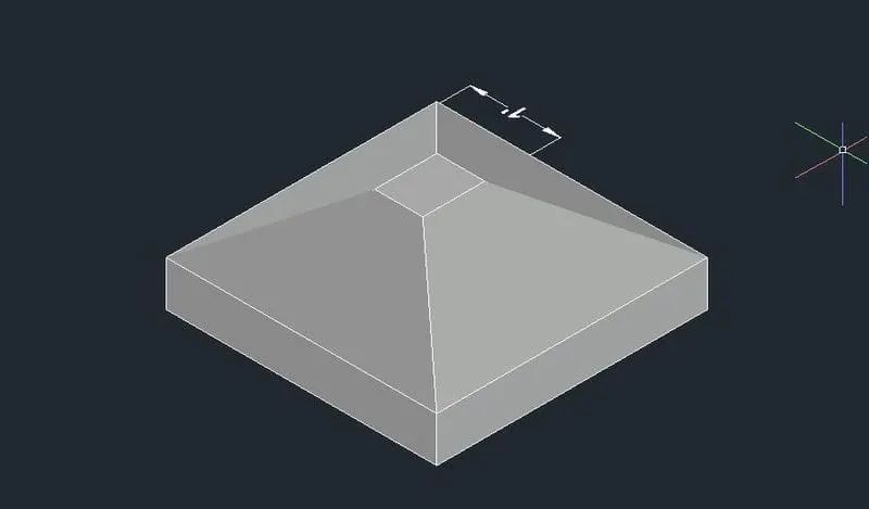
The diagram of 3D model of an isolated footing is drawn as per dimensions using the software of Auto.
DIAGRAM
3.AIM
To create a 3D View of the AASTHO type girder using the various commands in AutoCAD.
PROCEDURE
- To create a new sheet from application of AutoCAD.
- Go to the setting and to chamge the of page from Drafting to 3D modeling.
- Type"UN" to set the units of current format of measure.(feet and inches).
- Type "LIMITS" to set the maximum dimension limits on the particular page.
- First we take the top view of the page.
- To take "L"to create a line to draw the l section AASTHO Girder.
- The origin point is 0,0,0.
- The next point (@1'6",0,0).
- The next point is (@0,0,6").
- The next point is (@6"<0>
- Type"3D ORBIT"to view a 3D orbit viewport in the current viewport.
- Type"3D face" for allows to generate 3D faces by identifying.
- Type "REGION" to converts objects that encloses an area into a 2D region objects.
- Type "EXTRUDE" to create a surface or a 3D curve.
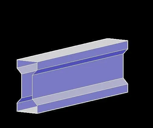
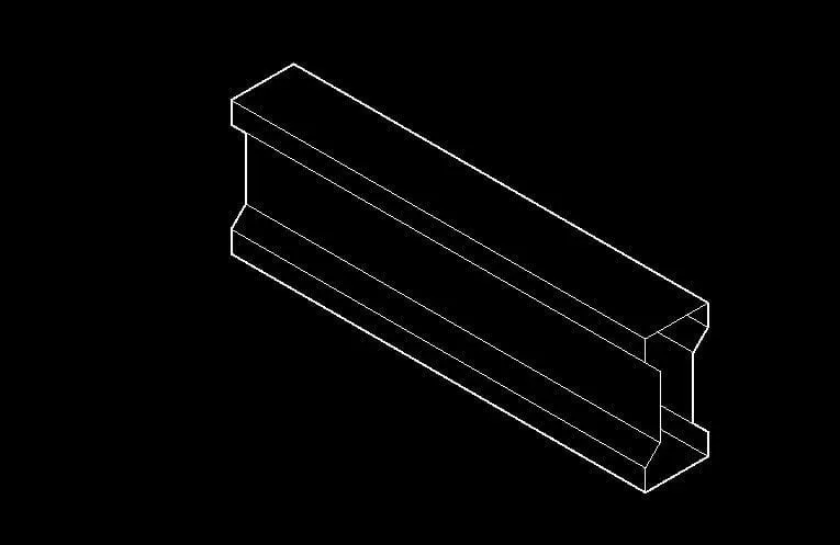
- The extruded length of the section Girder is 10 feet.
- Then,we have to change the view of 2d Wire,shaded,Conceptional,etc.
- To save the diagram to particular file.
RESULTS
The diagram of 3D type of AASTHO girder type is drawn as per dimensions using the software of AutoCAD.
DIAGRAM
4.AIM
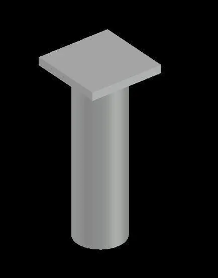
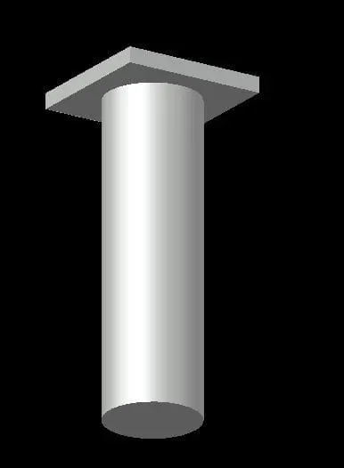
To create a 3D model of a drop column with panel using the various commands in AutoCAD.
PROCEDURE
- To create a new sheet from application of AutoCAD.
- Go to the setting and to change the view of the page from Drafting to 3d modeling.
- Type"UN"to set the units of current format of measure(feet and inches).
- Type "LIMITS" to set the maximum dimension limits on the particular page.
- First we take the top view of the page.
- Type"REC" to create a rectangle with a given dimensions.
- And then we take to a 3D custom view.
- To choose the top view of page.
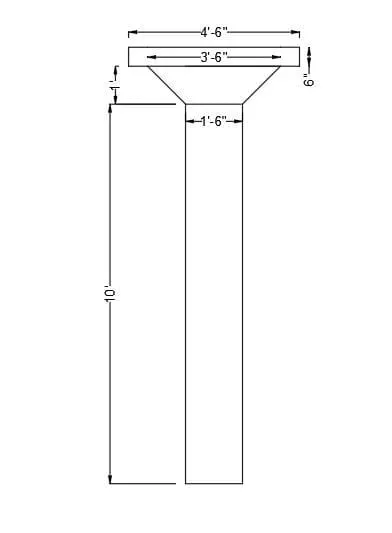
- The rectangular size is 4'6"
- Type "C" to create a circle options.
- The column cap height is 1 feet.
- The column head thickness is 6 inch.
- The height of the column is 10 feet.
- COPY-this commands is used to selected objects from a given square to destination,learning a copy at the originally selected location.
- MOVE-moves the objects to the destination place from the source place.
- After completed the the copy of rectangle to make the box like structure of column head.
- After we take to draw a circle of diameter of 1'6".
- Type"EXTRUDE"to create a surface or solid of a 2D surface or 3d curve.
- The extruted length of the circular column with a negative direction of Z is 10 feet.
- Type"3D ORBIT"to view a 3D orbit viewport in the current viewport.
- Type"3D FACE" for allows to generate 3D faces by identifying.
- Type"region" to converts objects that encloses an area into a 2D region objects.
- To save the diagram to particular file.
RESULTS
The diagram of 3D model of a column with drop panel is drawn as per dimensions using the software of AutoCAD.
DIAGRAM
5.AIM
To create a 3d model of a wall using the various commands in AutoCAD.
PROCEDURE
- To create a new sheet from application of AutoCAD.
- Go to the setting and to change the view of the page from Drafting to 3D modeling.
- Type"UN"to set the units of current format of measure(feet and inches).
- Type"LIMITS" to set the maximum demension limits on the particular page.
- First we take the top view of the page .
- Before we start the 3D work to create a plan of wall at 2D.
- To make the wall thickness of 250mm,
- To fix the door and wall opening from wherever we need.
- Type"REGION" to converts objects that encloses an area into a 2D region objects.
- After creating perfect plan to do next work of 3D solid works.
- Type"EXTRUDE"to create a surface or solid of a 2D surface or a 3D curve.
- The extruded of wall height is 10' from the base.
- And then to draw the rectangle of Wherever having the doors and windows.
- This comes after to follow the extruded of door opening height of 7 feet.
- Type"3D ORBIT" to view a 3D orbit viewport in the current viewport.
- Type"REGION"to converts objects that encloses.
- Type"SUBSTRACT" to remove the open required places of doors and windows.
- To save the diagram to particular file.
RESULTS
The diagram of 3D model of a wall is drawn as per dimensions using the software of AutoCAD.
DIAGRAM