Creating various 3D Models like Furniture, Footing, Girder, Column drop with panel and Gable Wall in AutoCad
ANS.1.
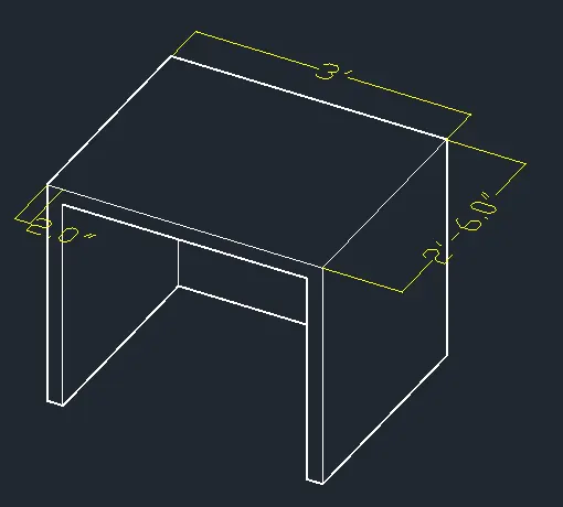
- AIM: To Create a 3D Furniture element as shown in the Figure.
- PROCEDURE :
- click on the AUTOCAD application
- command: QNEW
- click on ADVANCE SETTING
- UNIT: ENGINEERING precision 0'-0"
- ANGLE: DECIMAL DEGREE PRECISION 0
- ANGLE MEASURE: EAST AND CLICK ON NEXT
- ANGLE DIRECTION: COUNTERCLOCKWISE AND CLICK ON NEXT
- AREA: 50' X50'
- PRESS: ENTER
- command: un (for units )
- select the unit as ENGINEERING PRECISION 0'-0"
- SELECT SCALE AS INCHES
- PRESS: ENTER
- click on WORKSPACE SWITCHING
- Select the 3D MODELLING
- Then select the 2D wireframe
- command: L (for line )
- select the start point
- line specify next point @0,0.2'-6"
- line specify next point @0,0,3'
- line specify next point @0,0,2'-6"
- line specify next point @0,-2",0
- line specify next point @0,0.2'-4"
- line specify next point @0,-2'-10",0
- line specify next point @0,0,-2'-4"
- line specify next point @0,-2",0
- press: enter
- command: REC (for rectangle )
- select the start point
- click on DIMENSION
- length : 3'
- width: 2'
- press: enter
- go to the ANNOTATION TAB
- select the dimension
- and give the dimension to the figure
- command:3DFACE
- Specify all four points
- press: enter
- command: H (for hiding)
- select the object
- press: ENTER
- in this way give the surface to all faces
- by using command 3DFACE and HIDE Command
- press: ENTER
- RESULTS :
- COMMAND USED :
- START: QNEW
- UNITS: UN
- ZOOM: Z
- RECTANGLE: REC
- LINE: L
- 3DFACE : 3F
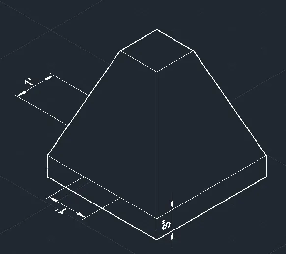
ANS.2.AIM: To Create the 3d Model of an Isolated footing as shown in Figure.
- PROCEDURE :
- click on the AUTOCAD application
- command: QNEW
- click on ADVANCE SETTING
- UNIT: ENGINEERING precision 0'-0"
- ANGLE: DECIMAL DEGREE PRECISION 0
- ANGLE MEASURE: EAST AND CLICK ON NEXT
- ANGLE DIRECTION: COUNTERCLOCKWISE AND CLICK ON NEXT
- AREA: 50' X50'
- PRESS: ENTER
- command: un (for units )
- select the unit as ENGINEERING PRECISION 0'-0"
- SELECT SCALE AS INCHES
- PRESS: ENTER
- click on WORKSPACE SWITCHING
- Select the 3D MODELLING
- Then select the 2D wireframe
- command: REC (for rectangle )
- select the first point
- click on DIMENSION
- Length : 3'
- width :3'
- press: enter
- command: REC (FOR RECTANGLE )
- select the start point
- click on DIMENSION
- length: 1'
- width: 1'
- press enter
- draw the rectangle in such a way that both rectangles have a same center point
- command: MOVE
- select the small rectangle
- click on the base point
- then give the height as @0,0,2'6"
- press: enter
- command: L (for line )
- select the start point
- and join the line
- show below
- press: enter
- command: 3Dface
- select the four-point
- press: enter
- command: H (for hiding)
- select object
- press: enter
- go to the ANNOTATION tab
- click on DIMENSION
- and give the dimension
- shown in fig
- press: enter
- RESULTS :
- COMMAND USED :
- START: QNEW
- UNITS: UN
- ZOOM: Z
- LINE: L
- RECTANGLE: REC
- LINE: L
- 3DFACE
- HIDE: H
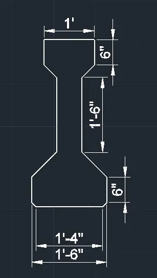
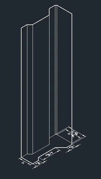
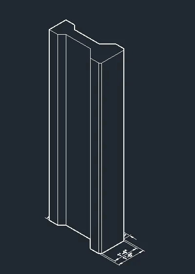
ANS.3.AIM: To Create the 3D view of the AASTHO Type Girder.
- PROCEDURE :
- click on the AUTOCAD application
- command: QNEW
- click on ADVANCE SETTING
- UNIT: ENGINEERING precision 0'-0"
- ANGLE: DECIMAL DEGREE PRECISION 0
- ANGLE MEASURE: EAST AND CLICK ON NEXT
- ANGLE DIRECTION: COUNTERCLOCKWISE AND CLICK ON NEXT
- AREA: 50' X50'
- PRESS: ENTER
- command: un (for units )
- select the unit as ENGINEERING PRECISION 0'-0"
- SELECT SCALE AS INCHES
- PRESS: ENTER
- click on WORKSPACE SWITCHING
- Select the 3D MODELLING
- Then select the 2D wireframe
- select the TOP view
- command : L (line )
- select the start point
- length specify next point @1'-6" ,0
- length specify next point @ 0,6"
- press: enter
- command: L (for line )
- select the start point
- length specify next point @0,6"
- length specify next point @ 6"<135
- length specify next point @0,1'6"
- length specify next point @6"<135
- length specify next point @0,6"
- length specify next point @0,6"
- length specify next point @1',0
- length specify next point @0,-6"
- length specify next point @0,-1'6"
- then click on closed
- press: ENTER
- go to the ANNOTATION TAB
- select the DIMENSION
- and give the dimension to the object
- command REGION
- select the object
- press: enter
- command: SHADED
- press: ENTER
- command: x (FOR EXPLODE )
- select the object
- give the height of exploding 10'
- press: enter
- RESULTS :
- COMMAND USED :
- QSTART: START
- UNITS: UN
- ZOOM: Z
- LINE: L
- REGION
- EXPLODE: X
- HIDE: H
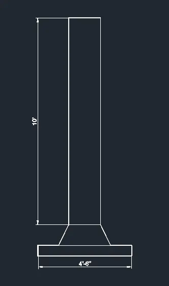
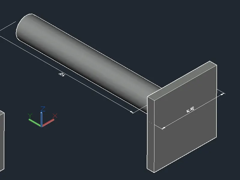
ANS.4.AIM: To Create a 3d Model of a drop column with the panel as shown in the section and isometric view.
- PROCEDURE :
- click on the AUTOCAD application
- command: QNEW
- click on ADVANCE SETTING
- UNIT: ENGINEERING precision 0'-0"
- ANGLE: DECIMAL DEGREE PRECISION 0
- ANGLE MEASURE: EAST AND CLICK ON NEXT
- ANGLE DIRECTION: COUNTER CLOCKWISE AND CLICK ON NEXT
- AREA: 50' X50'
- PRESS: ENTER
- command: un (for units )
- select the unit as ENGINEERING PRECISION 0'-0"
- SELECT SCALE AS INCHES
- PRESS: ENTER
- click on WORKSPACE SWITCHING
- Select the 3D MODELLING
- Then select the 2D wireframe
- take the USC Direction shown below
- select the TOP view
- command: L (for line )
- select the start point anywhere
- length specify next point @6",0
- length specify next point @0,4'-6"
- length specify next point @-6",0
- length specify next point @0,-4'-6"
- press: enter
- command: L (for line )
- select the start point
- length specify next point @6"<45
- length specify next point @-10',0
- length specify next point @0,1'-6"
- length specify next point @-10,0
- then closed
- press: enter
- go to the annotation tab
- click on DIMENSION
- and give the dimension
- OBJECT NO: 2
- PROCEDURE :
- go to the customer view
- command: REC (for rectangle )
- give the starting point
- click on the dimension
- give the starting point
- length : 4'5"
- width : 4'5"
- press: enter
- command: c (for circle )
- select the start point
- click on DIAMETER
- diameter : 3'5"
- press: enter
- command: C (for circle )
- select the start point
- click on the diameter
- diameter : 1'5"
- press: enter
- command: M (for the move )
- select the object
- select the base point
- give the height as @0,0,1'
- press: enter
- command: REGION
- select the object
- press: enter
- command: SHADED
- press: enter
- command: X (for explode )
- select the object
- give the height is 10'
- press: enter
- go to the REBIEN
- CLICK ON PRESS PULL
- SELECT THE RECTANGLE
- AND PRESS IT AS SHOWN IN FIG
- RESULTS :
- COMMAND USED :
- START: QSTART
- UNITS: UN
- LINE: L
- REGION
- EXPLODE: X
- PAN :P
- SHADED
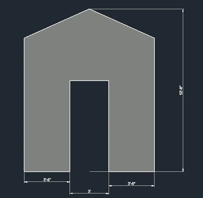
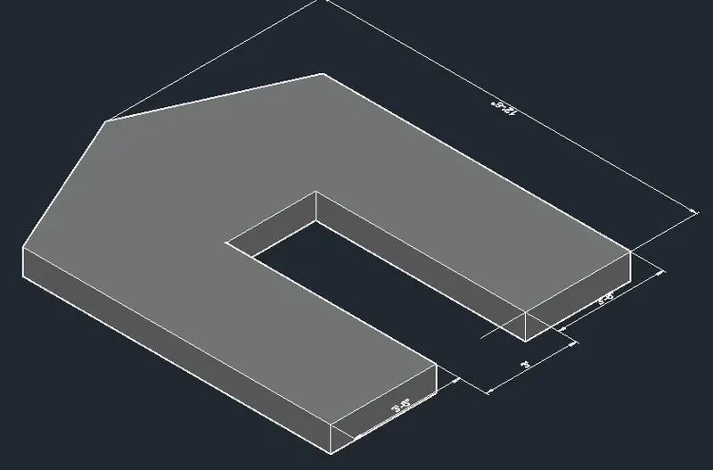
ANS.5.AIM: To Create the 3d model of a wall as shown in Figure. Consider wall thickness as 9”.
- PROCEDURE :
- click on the AUTOCAD application
- command: QNEW
- click on ADVANCE SETTING
- UNIT: ENGINEERING precision 0'-0"
- ANGLE: DECIMAL DEGREE PRECISION 0
- ANGLE MEASURE: EAST AND CLICK ON NEXT
- ANGLE DIRECTION: COUNTERCLOCKWISE AND CLICK ON NEXT
- AREA: 50' X50'
- PRESS: ENTER
- command: un (for units )
- select the unit as ENGINEERING PRECISION 0'-0"
- SELECT SCALE AS INCHES
- PRESS: ENTER
- click on WORKSPACE SWITCHING
- Select the 3D MODELLING
- Then select the 2D wireframe
- take the USC Direction shown below
- command: L (for line )
- select the start point
- length specify next point @3'6",0,0
- length specify next point @0,0'.7'
- length specify next point @3',0,0
- length specify next point @0,0,-7'
- length specify next point @3'6",0,0
- length specify next point @3'6",0,0
- length specify next point @0,0,10'
- press: enter
- command: L (for line )
- select the start point as a midpoint of
- length specify next point @0,0,12'6"
- press enter
- by using the line command join the lines as shown in fig
- go to the ANNOTATION tab
- click on DIMENSION
- and give the dimension
- press: enter
- command: REGION
- Select the object
- press: enter
- command: CONCEPTUAL
- Press: ENTER
- command: X (for explode )
- select the object
- give the HEIGHT of exploding 9"
- press: enter
- RESULTS :
- COMMAND USED :
- START: QSTART
- UNITS: UN
- LINE: LINE
- TRIAM: TR
- REGION
- HIDE: H
THANK YOU!!!!!!!!!!!!!!!!!!!!!!!!!