Creating various 3D Models like Furniture, Footing, Girder, Column drop with panel and Gable Wall in AutoCad
Question
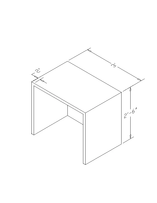
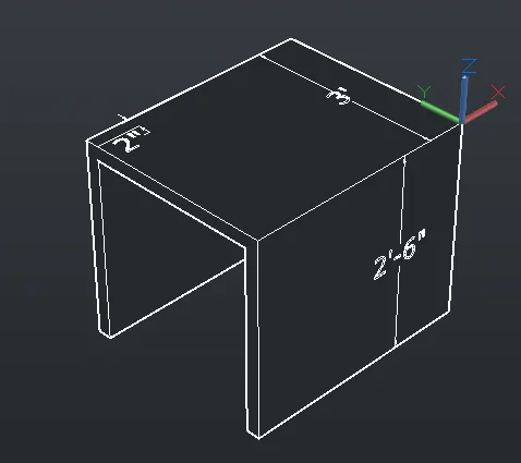
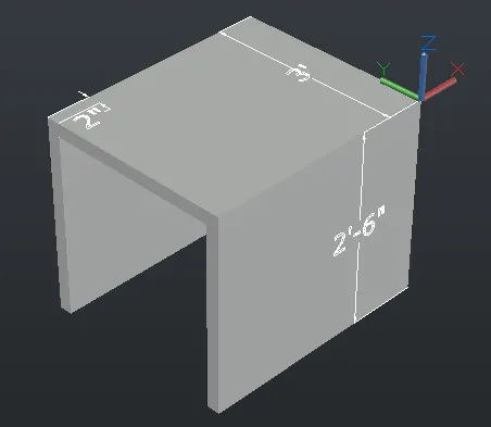
1. Create a 3D Furniture element as shown in the Figure. Assume dimensions which are missing.
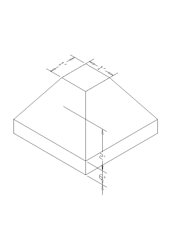
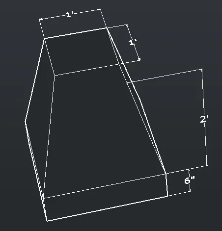
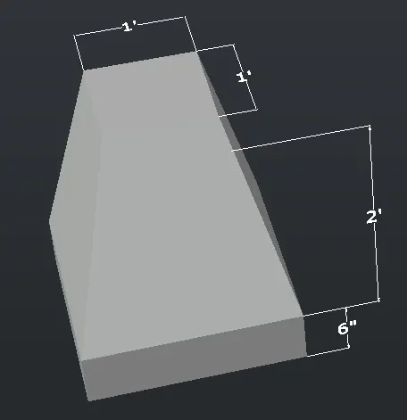
2. Create the 3d Model of an Isolated footing as shown in Figure.
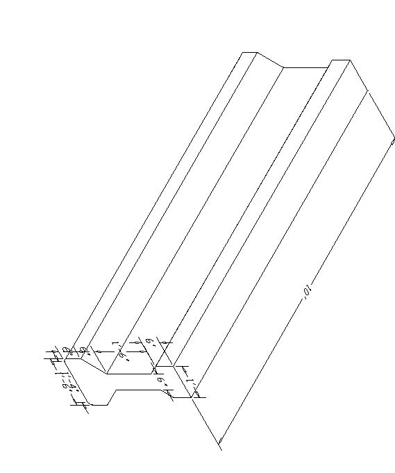
3. Create the 3D view of the AASTHO Type Girder.
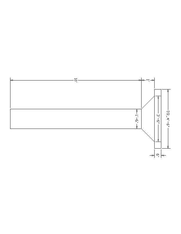
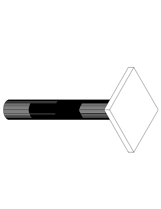
4. Create a 3d Model of a drop column with panel as shown in section and isometric view.
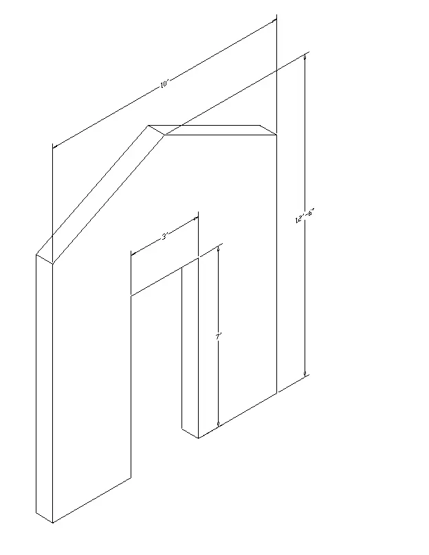
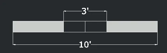
5. Create the 3d model of a wall as shown in Figure. Consider wall thickness as 9”.
1. Create a 3D Furniture element as shown in the Figure. Assume dimensions which are missing?
1. AIM :- To create 3D model and view of:
- Furniture element
- Isolated footing
- AASTHO type girder
- Drop column with panel
- A wall
Commands used :-
- Extrude.
- Offset.
- UCS.
- Box.
- Union.
- Subtract.
- Move.
- 3d orbit.
- Loft.
- Sweep.
- Cone.
- Region.
- Boundary.
PROCEDURE:
Open the AutoCAD, click on workspace switching and change it to 3d modelling and click on the home button near the view cube.Set the limits and zoom - all.
DRAWING OF 3D FURNITURE ELEMENT:
1).
Aim: To create a 3D model of the furniture element.
Procedure:
Step1:Select imperial in AutoCAD since the units are in feet and inches.To allow for the insertion of feet and inches, go to units' command and set it to engineering.
Step 2: Create a box by selecting the length option from the toolbar or box command, then entering 3' and 2'6" for the length and width.If height must be mentioned, state that you are 2'6".
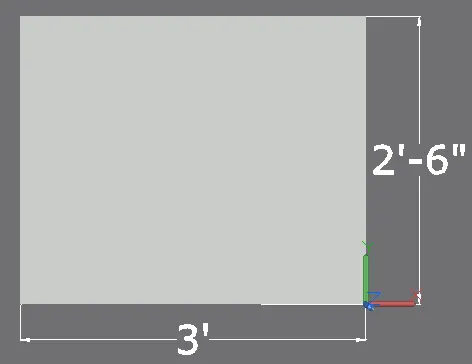
Step 3:
To select the front face, either click on the face and choose it, or use the command "ucs" to provide the x and y coordinates in the front face, respectively.To properly align the front face, type the command "PLAN."
Step 4:
From the right side of the front view, draw a line that is 2" long.Draw a rectangle with the dimensions 32" and 2'4" using the rectangle command. (as the thickness is given as 2")
step 5 :
Move the rectangle to the line that was previously drawn 2" from the right side of the face in step 5.
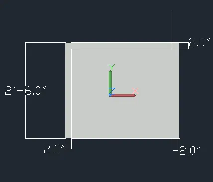
Step 6: Delete the line created earlier.Now with command "3do" orbit the object and select the rectangle.
Step 7: The rectangle should be extruded to the -z axis at a 2'4" thickness.Give the command "Subtract" now and choose the larger object in the 2D wireframe model followed by the smaller extruded rectangle.
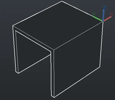
Step 8: Dimensions are given by dim linear command by switching the UCS.
Result: The 3d model of furniture element is created.
2. Create the 3d Model of an Isolated footing as shown in Figure
2).
3D MODEL OF ISOLATED FOOTING:
Aim: To create a 3d model of isolated footing
Procedure:
Step 1: Create a rectangle of 2' x2' on the top view.Create another rectangle of 1'x1' on the top view.
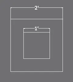
Step 2: Rotate the view to the appropriate one using the command "3do" in 3D orbit.Move the 1-by-1-by-2-inch rectangle with ortho on by using the "M" move command.
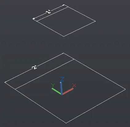
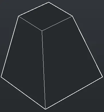
Step 3: Click on the loft from the home toolbar and select the two rectangles to loft.
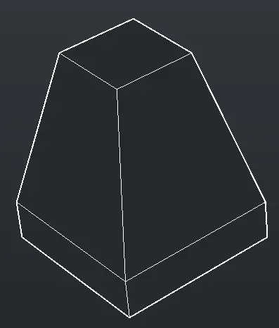
Step 4: Return to the top view and draw a rectangle of the same size on top of the larger rectangle.Extrude can be selected from the home toolbar by clicking on it, then the mouse is used to select the created rectangle, specify a height of 6", and choose the direction of extrusion.
Step 5:By using UCS command give the dimensions.
Result:
3. Create the 3D view of the AASTHO Type Girde
3).
3D MODEL OF A AASTHO TYPE GIRDER
Aim: To create a 3d model of AASTHO type girder using AutoCAD 3d.
Procedure:
Step 1:
select "front view"Make the x and y axes in the front view plane using the UCS command.
Step 2:
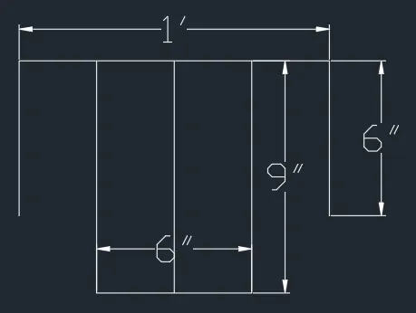
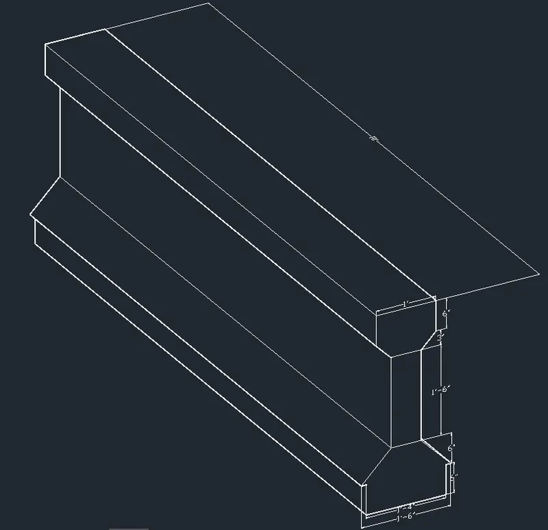
The I section with the specified dimension is then drawn using the line command.Using the command "L," draw a line 1' wide—the top dimension of the girder.
The line should be drawn 6" downward.Draw a line with snap on starting at the centre of 1' and offset 3" on either side so that the web width becomes 6".
Step 3:
Connect the web and the flange after providing a taper distance.the same in reverse on the opposite side
The web is given a height of 1'6", offset by 1'6" from the point where the flange portion begins to taper (1').Trim off the extra lines in the flange and remove the centre line drawn for the offset.
Step 4:
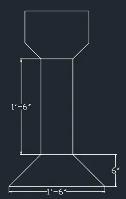
Increase the web's offsite line.Once more, offset the last line by 6", then taper the sides.To the opposite side, reflect the tapered section.Draw a centre line, offset it on both sides by 9, and then join the tapered sides together so that the bottom is 1'6".
Step 5:
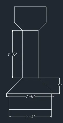
To determine the height, subtract 6" from the bottom horizontal line.Draw a line from the centre and offset it on both sides by 8" to create the taper at the bottom, which is 1'4".
Step 6:Extend the 6" offsite line and trim the rest of lines.Draw the vertical line downwards and the tapering also.
Step 7:
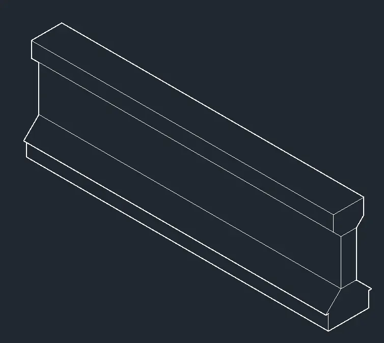
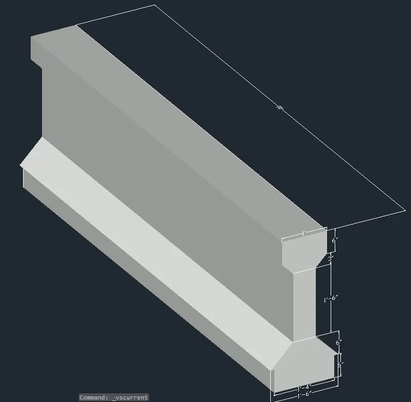
Turn the view while using 3D Orbit, then draw a 10' line in the z direction.Select the section to be swept, followed by the line that it should travel through, by clicking on sweep in the home toolbar.
Result:
The 3D model of the AASTHO girder is drawn:
4. Create a 3d Model of a drop column with panel as shown in section and isometric view
4).
3D MODEL OF A DROP COLUMN WITH PANEL
Aim: To draw the 3d model of a drop column with panel section and show its isometric view.
Procedure:
Step 1:
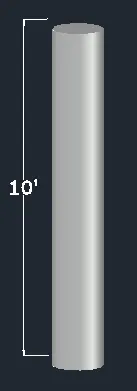
Create a circle of diameter 1'6” in the top view.
Step 2:Select the rectangle and create a command that runs regions by regions.Use the extrude tool in the home toolbar to extend it 10'.
Step 3:
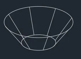
By selecting cone from the home toolbar, a cone can be created.Give the base diameter of 1'6 by clicking on diameter.
Step 4:
Click on top radius and give the value as 1'6" and give the height of the cone as 1".
Step 5:
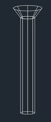
In the front view, place the cone's frustum on top of the column; use the snap option to align the centres of the two objects. In the top view, align the frustum's centre with the column's centre.
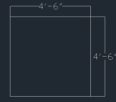
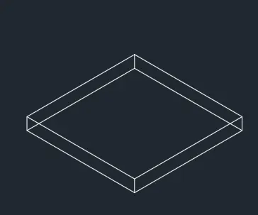
Step 6: In top view, create a rectangle of dimension 4'6" x4'6".Extrude it to a height of 6".
Step 7:
Place the rectangle in the centre of the cone in the top view and adjust it in the front view as well. You can also give the move command with the coordinates 0,10',0 since the rectangle is at the bottom in the front view.
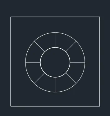
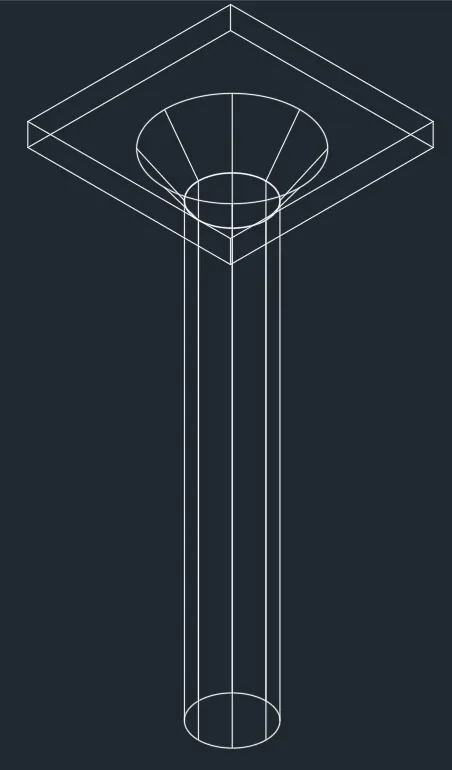
3D view
Result:
The 3d model of a drop column with panel has been drawn section and isometric view is also shown:
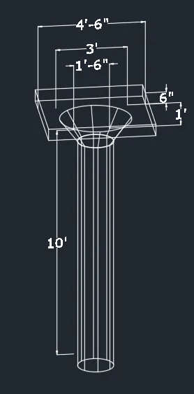
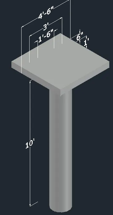
5. Create the 3d model of a wall as shown in Figure. Consider wall thickness as 9
5).
3D MODEL OF WALL
Aim: To draw a 3d model of wall.
Procedure
Step 1:
Draw a rectangle of 10' x 9".Create a line in the center and offset 1.5" on both sides as 3" is the width of door opening.
Step 2:
Create the region, that is, the area on either side of the door opening, by using the boundary command "BO."
Step 3: Extrude the region to a height of 12'6" total height.
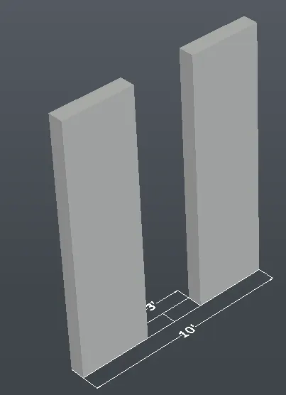
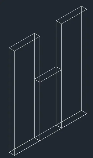
Step 4:
In the top view, draw a rectangle to replace the door.Move the rectangle 7' from the bottom in the z axis.
Step 5: Draw a line from the middle of the door's moved line in front view.Draw a slanting line from the centre line intersecting the edge at its total height.
Step 6: Mirror the line to the other side.Draw the horizontal line to join.
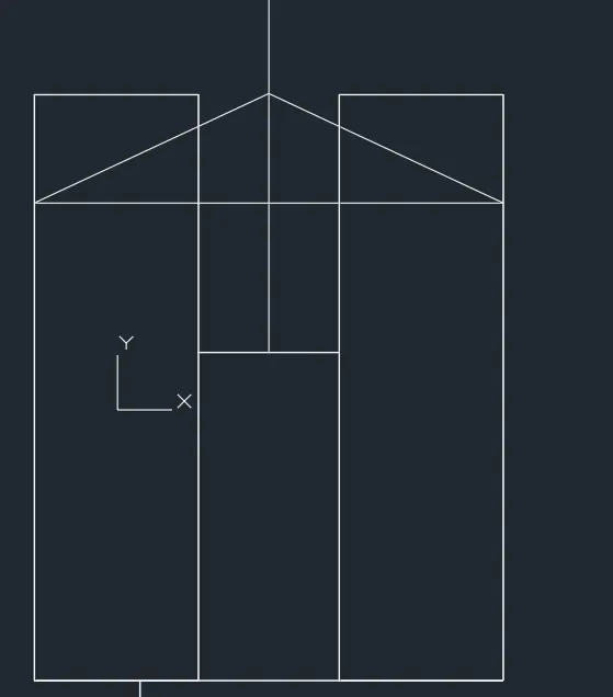
Step 7: trim off the excess line and the center line and join the triangle with join command.Create a region with region command in the triangle created.
Step 8:
Choose the extruded rectangle, then use your grip to lower it until both of its sides are at the level of the triangle's base.Extrude the door's rectangle to a height equal to the triangle's base.
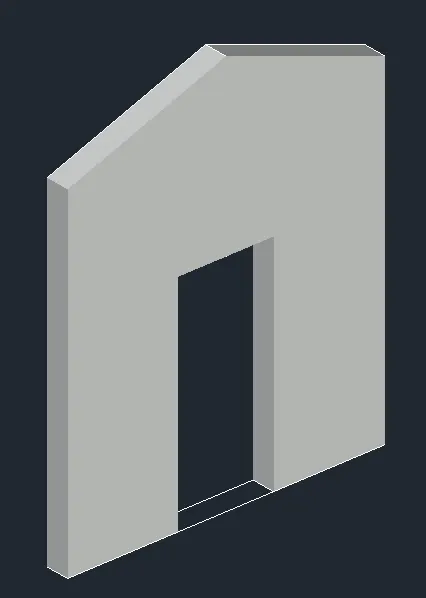
Result: 3d model of wall is drawn.
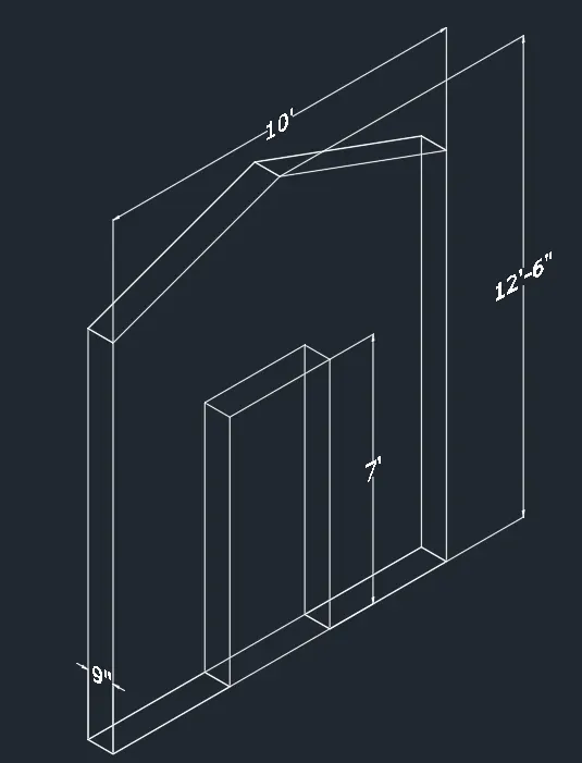
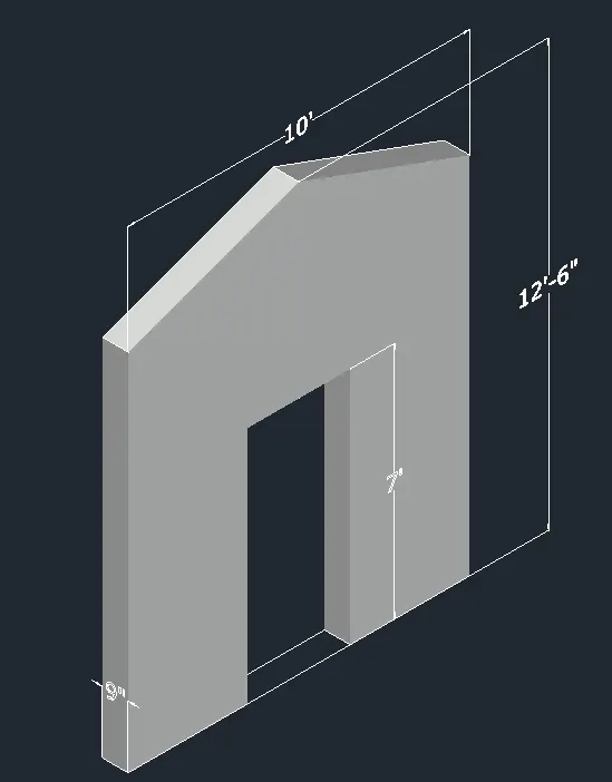
RESULT:
- 3d model of furniture element is created.
- 3d model of isolated footing is created.
- 3d model of AASTHO type girder is created.
- Drop column with panel 3d model is created.
- 3d model of wall is created.