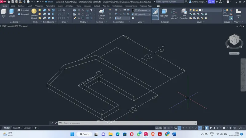
Creating various 3D Models like Furniture, Footing, Girder, Column drop with panel and Gable Wall in AutoCad
Aim: Creating a different 3D models by using autocad. The models creating by autocad are 3D furniture element,3D model of an isolated footing,AASTHO type Girder3d model of a drop column with panel and 3d model view of a wall
Introduction: 3D model is a type that shows the objects in 3D view that created in autocad software. Such tools are used like extrude,region,shade,union,substract and etc., It is an intresting thing that we see in the autocad software. Such 3D drawing are drawn below by using autocad siftaware
- 3D Furniture element:-
Procedure:
Type UN in the comman line
Set the units as engineering
Now type limits in the command line
Set the lower limit as 0,0 and upper limit as 100,100
Now press Z enter and A enter to fit the screen
Type LINE in the command line to activate the line tool
Specify the starting point
Specify next point as 0,0,2'6"
Specify next point as 0,-3',0
Specify next point as 0,0,-2'6"
Specify next point as 0,2",0
Specify next point as 0,0,2'4"
Specify next point as 0,2'8",0
Specify next point as 0,0,-2'4"
And join the line
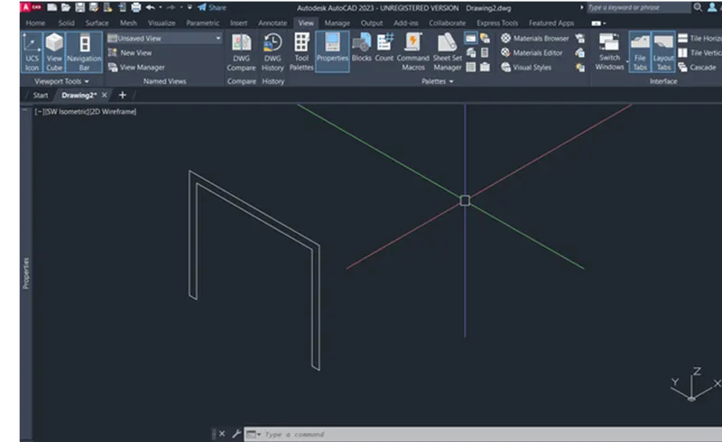
Now type region in the command line to create a region of object
Select the object and press enter the region is created
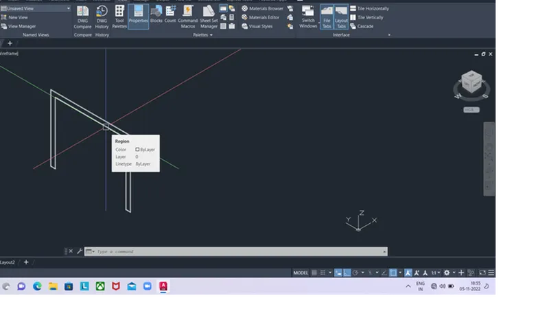
Now type extrude in the comman line
Extrude the object in x axis
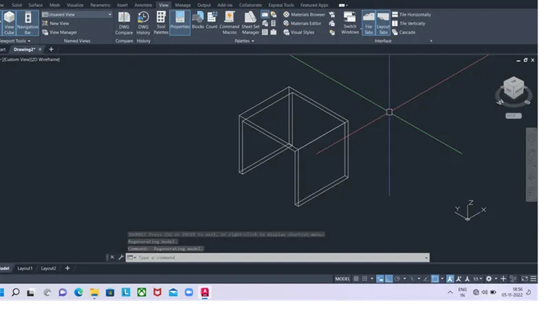
Now type 3DFACE in the command line to activate the 3Dface tool
Select the faces of the object to create a surface
After creating the all faces into surface type hide in the command line
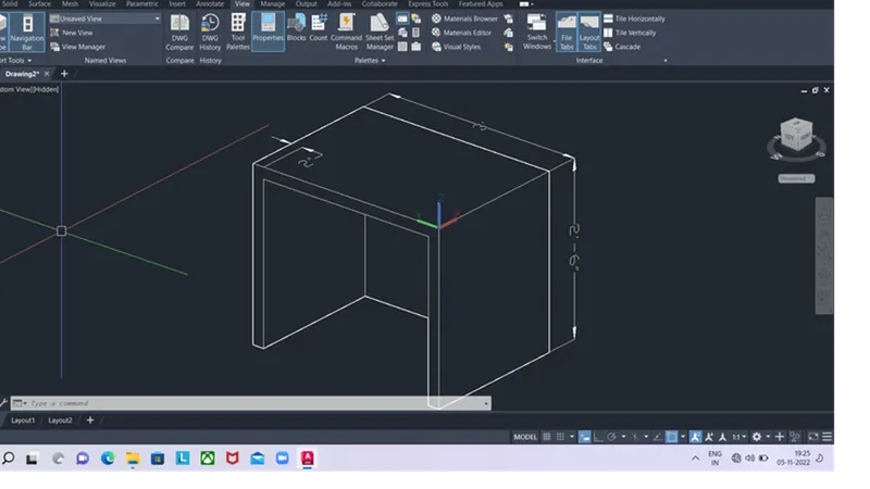
Now give the dimension to the object by DIMLIN tool
The UCSICON at a certain point so that we can give the dimension in the XY plane
Result
2Q. 3D Model Isolated footing
Aim: Creating the 3D Isolated footing
Procedure:-
Type UN in the comman line
Set the units as engineering
Now type limits in the command line
Set the lower limit as 0,0 and upper limit as 100,100
Now press Z enter and A enter to fit the screen
Type REC in the command line
Specify the starting point
Type D and press enter
Give the dimensions as 1' length and 1' breadth
Now make a region by typing region in the command line
Now type EXTRUDE in the command line
Select the object and select the taper option in the command
Specify the angle as -30 degress and height as 2"
By using line tool draw the line at 4 corners of the drawing
Take the 6" length of the line
And join the lines by using line tool
Now by using 3DFACE tool create surfaces of all side of the object
After creating the all faces into surface type hide in the command line
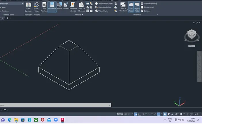
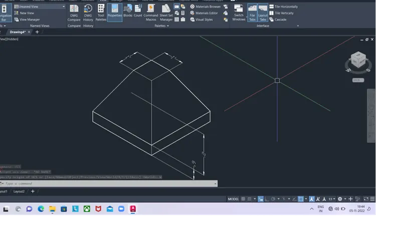
Now give the dimension to the object by DIMLIN tool
The UCSICON at a certain point so that we can give the dimension in the XY plane
Result:
3Q. 3D View of AASTHO type girder
Aim: Creatig the 3D View of AASTHO type girder
Procedure:-
Type UN in the comman line
Set the units as engineering
Now type limits in the command line
Set the lower limit as 0,0 and upper limit as 100,100
Now press Z enter and A enter to fit the screen
Now in settings 3D Modelling and visual style control to 2D wire frame
Now using the line command
Draw the given drawing with same dimensions
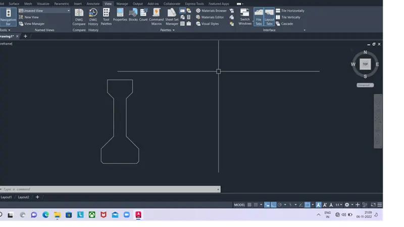
Give the dimensions to the object same as in the question
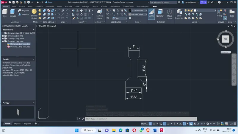
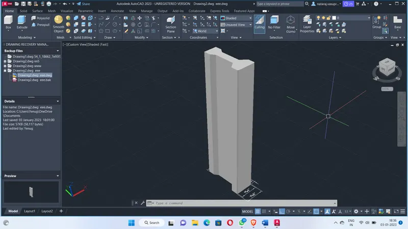
After this extrude the object upto 10'
Result:
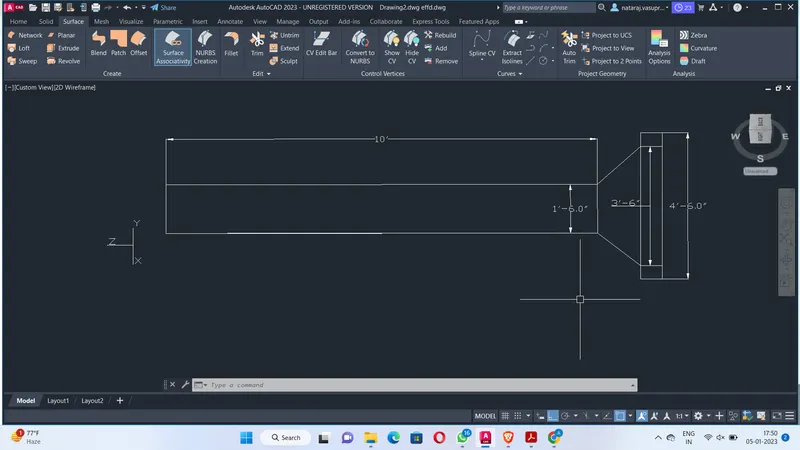
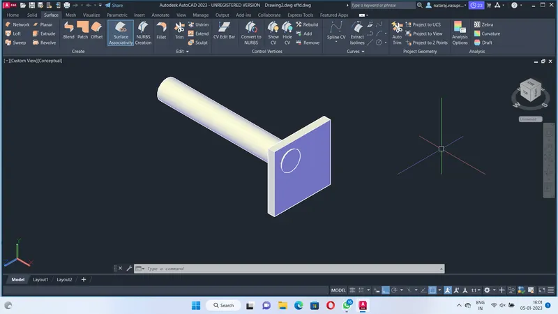
4. Create a 3d Model of a drop column with panel as shown in section and isometric view.
Aim: To draw the 3d model of a drop column with panel section and show its isometric view.
Procedure:
Step 1:
Create a arc of width 1'6”and the length of 10' in the top view on both the sides.
Step 2:
with line commad draw the sqare with the length of 4'6"
Step 3:
Then type region and select the object then extrude the object of height 6"
Step 4:
In the top view, place the rectangle at the center of circle and also adjust in the front view or give move command as the rectangle is at bottom in the front view.
Result:
The 3d model of a drop column with panel has been drawn section and isometric view is also shown:
Q5. 3D model wall
Aim:- Creating 3Dmodel of wall
Procedure -
Type UN in the comman line
Set the units as engineering
Now type limits in the command line
Set the lower limit as 0,0 and upper limit as 100,100
Now press Z enter and A enter to fit the screen
Now in settings 3D Modelling and visual style control to 2D wire frame
Using the line command and given dimensions the points was plotted
Type Region and press enter, and select the model created to convert it.
Click on Extrude option in home tab and then select the model and at a height of 9".
The visual style control was changed to hidden
Using the DIMLIM command the dimensioning
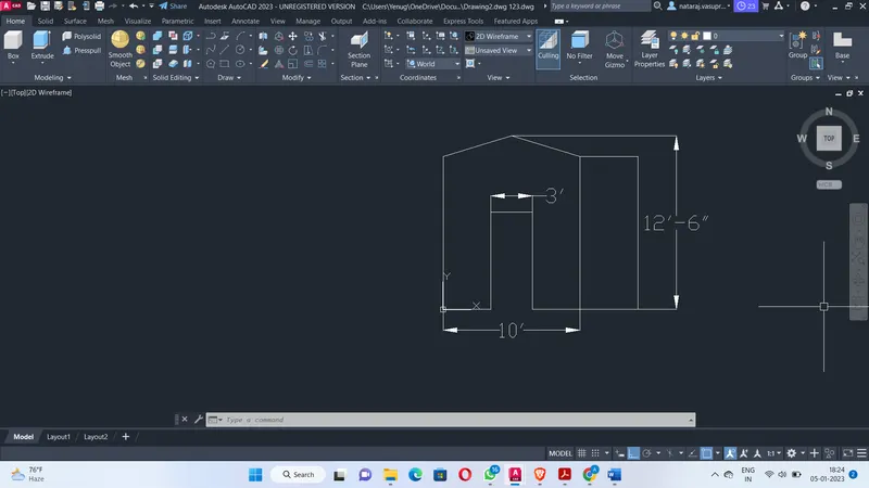
Result: