Creating various 3D Models like Furniture, Footing, Girder, Column drop with panel and Gable Wall in AutoCad
AIM :- To create a 3D furniture element as shown in figure above in AutoCAD.
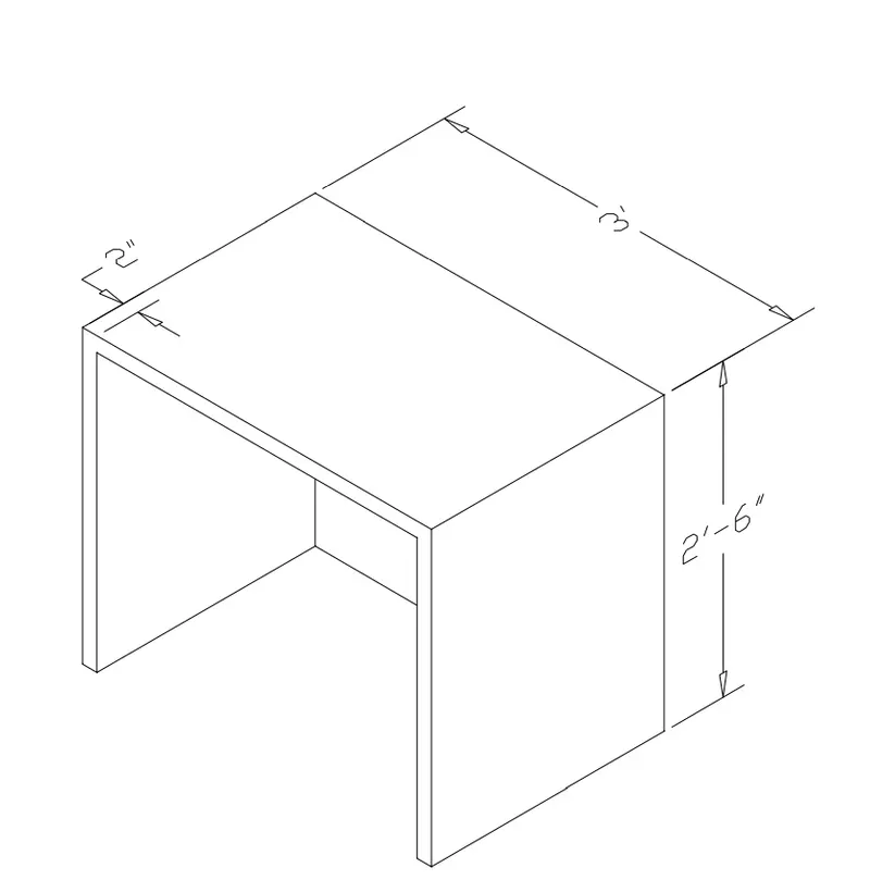
INTRODUCTION :- 3D furniture is created in AutoCAD in 3D modelling workspace by using LINE tools. The procedure of drawing is explained in detail with diagrams of each step and the final result is given.
PROCEDURE :-
STEP 01.
- Go to START MENU select AutoCAD
- In Command prompt type STARTUP then enter
- Enter new value of startup as 1
- Go to application menu and select NEW
- Select IMPERIAL, then ok
- Type UNIT command
- In drawing unit dialog box select ENGINEERING
- In precision select 0’-0”
- INCHES in insertion scale then ok
- Select 3D Modelling from the workplace
- Set limits by entering LIMIT command
- Lower-left corner 0’0”,0’0” and upper-right corner 100’,100’
STEP 02.
- Type LINE in command prompt
- Specify first point : @0,0,0 then enter
- Specify next point : @0,0,2’6” enter
- Specify first point : @0,3’,0 then enter
- Specify next point : @0,0,-2’6” enter
- Specify first point : @0,-2”,0 then enter
- Specify next point : @0,0,2’4” enter
- Specify first point : @0,-2’8”,0 then enter
- Specify next point : @0,0,-2’4” enter
- Specify first point : @0,-2”,0 then enter
- Again type LINE in command prompt
- Specify first point : select top left corner of the box
- Specify next point : @2’6”,0,0 then enter
- Specify next point : @0,-3’,0 enter
- Specify next point : @-2’6”,0,0 then enter
- Again type LINE in command prompt
- Specify next point : @2’4”,0,0 enter
- Specify next point : @0,-2’8”,0 then enter
- Specify next point : @0,0,-2’4” enter
- Specify next point : @-2’4”,0,0 enter
- Again type LINE in command prompt
- And draw other remaining line by using LINE command to perpendicular
STEP 03.
- Enter 3DFACE in command prompt
- Draw four point covering to other face enter
- Enter HIDE in command prompt
STEP 04.
- Enter DST command
- Click on Modify tab
- In Symbols and Arrows option change Arrow size to 3”
- In Text option change text height to 3”
- Then click OK then click on SET
- After that use DIMLINE command to show all dimensions
RESULT :-
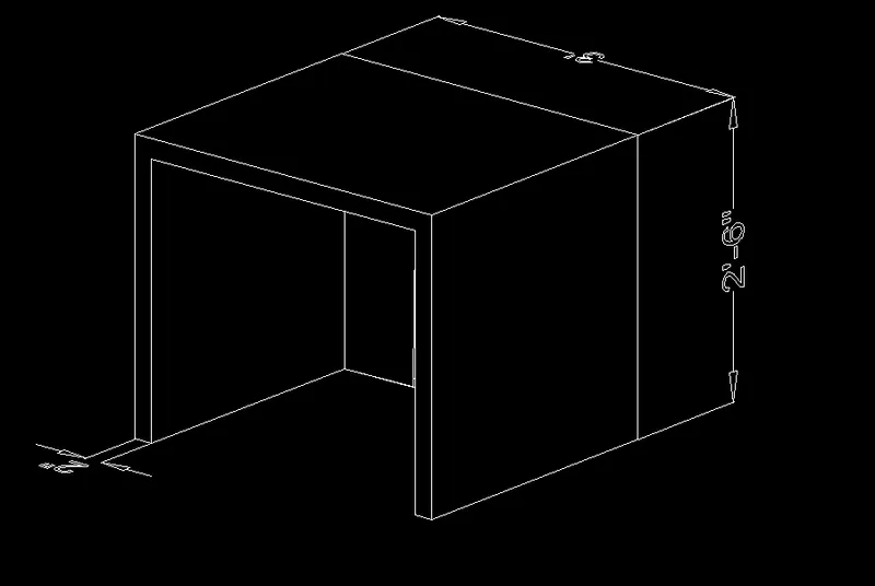
- All dimensions are in feet & inches.
- 3D furniture element is created as shown in figure.
AIM :- To create the 3D model of an isolated Footing as shown in figure above in AutoCAD.
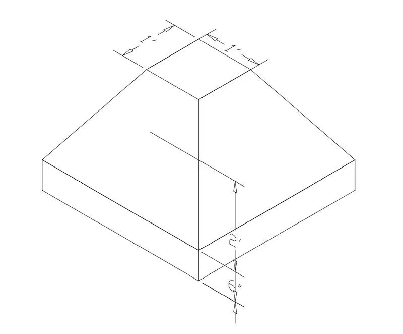
INTRODUCTION :- 3D model of the isolated footing is created in AutoCAD in modelling workspace by using LINE & RECTANGLE tools. The procedure of drawing is explained in details with each steps and final result is given.
PROCEDURE :-
STEP 01.
- Go to START MENU select AutoCAD
- In Command prompt type STARTUP then enter
- Enter new value of startup as 1
- Go to application menu and select NEW
- Select IMPERIAL, then ok
- Type UNIT command
- In drawing unit dialog box select ENGINEERING
- In precision select 0’-0”
- INCHES in insertion scale then ok
- Select 3D Modelling from the workplace
- Set limits by entering LIMIT command
- Lower-left corner 0’0”,0’0” and upper-right corner 100’,100’
STEP 02.
- Type RECTANGLE in command prompt
- Specify the first corner : @0,0,0 then enter
- Specify other corner : @ 3’,3’ then enter
- Again type RECTANGLE in command prompt
- Specify first point : select anywhere
- Specify other corner : @1’,1’ then enter
- Then use MOVE command to move the smaller rectangle to the geometric centre or bigger rectangle
- Again enter MOVE command to move the smaller rectangle towards upper as height of 2’6” to the (Z axis)
- Type EXTRUDE in command prompt select the large rectangle and extrude to height of 6”
- Now use LINE command to connect all other lines from the smaller rectangle to large rectangle
STEP 03.
- Ener 3DFACE command
- Draw four point face covering all sides of footing
- Enter HIDE in command prompt
STEP 04.
- Enter DST command
- Click on Modify tab
- In Symbols and Arrows option change Arrow size to 3”
- In Text option change text height to 3”
- Then click OK then click on SET
- After that use DIMLINE command to show all dimensions
RESULT :-
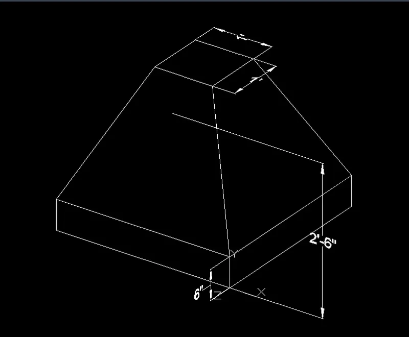
- 3D model of isolated footing is completed by using AutoCAD as shown in figure.
- All dimensions are in feet & inches.
AIM :- To create the 3D view of the AASTHO type girder as shown in figure.
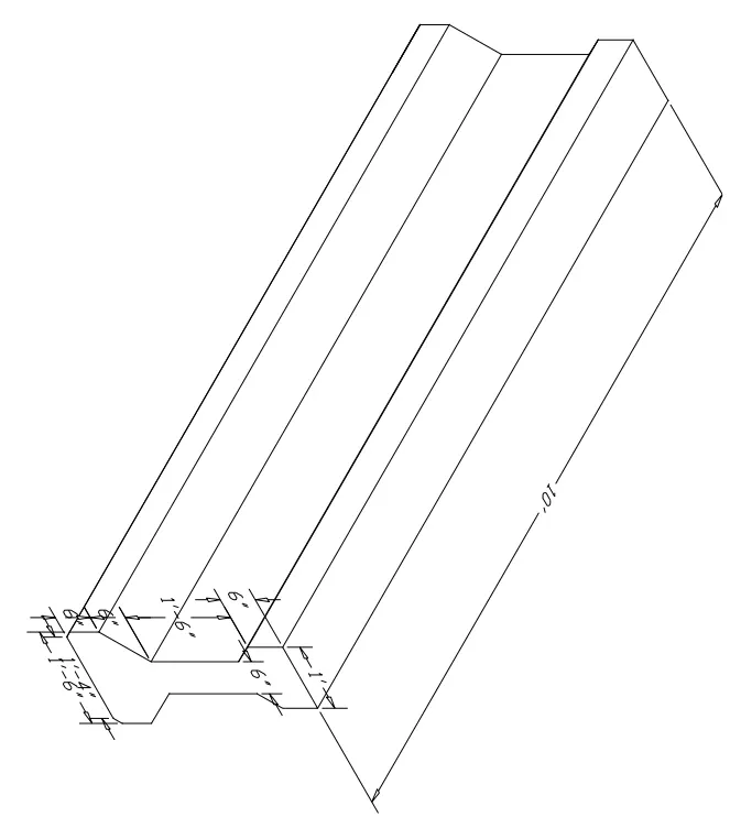
INTRODUCTION :- 3D view of the AASTHO type girder is created in AutoCAD in 3D modelling workplace by using LINE & CHAMFER tool. The procedure of drawing is explained in detail with each steps and final result is given.
PROCEDURE :-
STEP 01.
- Go to START MENU select AutoCAD
- In Command prompt type STARTUP then enter
- Enter new value of startup as 1
- Go to application menu and select NEW
- Select IMPERIAL, then ok
- Type UNIT command
- In drawing unit dialog box select ENGINEERING
- In precision select 0’-0”
- INCHES in insertion scale then ok
- Select 3D Modelling from the workplace
- Set limits by entering LIMIT command
- Lower-left corner 0’0”,0’0” and upper-right corner 100’,100’
STEP 02.
- Select the Top view in the view cube
- Enter LINE in command prompt
- Specify first point : 1’6” (x-axis)
- OFFSET in command prompt
- Take OFFSET of 6” in upward direction twice
- Again OFFSET in command prompt
- Take OFFSET of 1’6” from last offset line
- Again OFFSET in command prompt
- Take OFFSET of 6” in upward direction
- Now take LINE command
- And select the middle of bottom top 3rd line take some height upward for reference
- Now OFFSET 6” left & right of that middle line
- Now increase both line toward top line
- Now use CHAMFER command at distance of 1”
- Now select the bottom of left & right respectively for chamfer
- Now use LINE & TRIM command to complete the object
STEP 03.
- Enter BOUNDARY in command prompt
- Select the pick point icon in boundary creation box
- Now select the object
- Now EXTRUDE in command prompt
- Select the object and extrude at height of 10’
STEP 04.
- Enter DST command
- Click on Modify tab
- In Symbols and Arrows option change Arrow size to 3”
- In Text option change text height to 3”
- Then click OK then click on SET
- After that use DIMLINE command to show all dimensions
RESULT :-
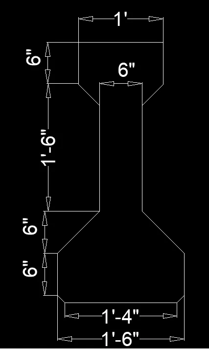
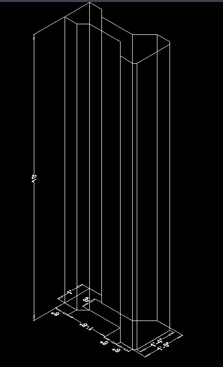
- 3D view of the AASTHO type girder is competed by using AutoCAD as shown in figure.
- All dimensions are in feet & inches.
AIM :- To create the 3D model of a drop column with panel in section and isometric view as shown in the figure.
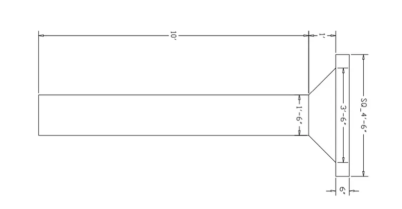
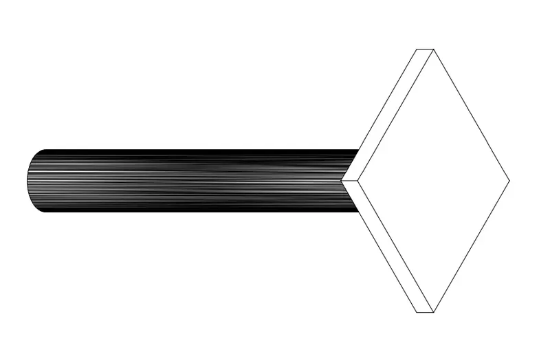
INTRODUCTION :- 3D model of a drop column with panel as shown in section and isometric view is created in AutoCAD in 3D modelling workplace by using LINE CIRCLE & RECTANGLE command. The procedure of drawing is explained in detail with each steps and the final result is given.
PROCEDURE :-
STEP 01.
- Go to START MENU select AutoCAD
- In Command prompt type STARTUP then enter
- Enter new value of startup as 1
- Go to application menu and select NEW
- Select IMPERIAL, then ok
- Type UNIT command
- In drawing unit dialog box select ENGINEERING
- In precision select 0’-0”
- INCHES in insertion scale then ok
- Select 3D Modelling from the workplace
- Set limits by entering LIMIT command
- Lower-left corner 0’0”,0’0” and upper-right corner 100’,100’
STEP 02.
- Type RECTANGLE in command prompt
- Specify first corner : @0,0,0
- Specify other corner : @4’6”,4’6” enter
- EXTRUDE it to height of 6”
- Type CIRCLE in command prompt
- Specify the centre of the circle : click anywhere
- Select diameter : 3’6”
- Again use CIRCLE command
- Specify centre of the circle : click centre of last circle
- Select diameter : 1’6”
- Select LOFT command
- Then select large circle & small circle enter
- Now use MOVE command for moving the loft object select the centre of that & put it at the centre of geometric centre
- Now again use CIRCLE command
- Select the centre : select last circle centre
- Select diameter : 1’6”
- Now ETRUDE it to height of 10’
- Now use 3DROTATE command to rotate as shown in figure
STEP 03.
- Enter 3DFACE in command prompt
- Draw four point covering to other face enter
- Enter HIDE in command prompt
STEP 04.
- Enter DST command
- Click on Modify tab
- In Symbols and Arrows option change Arrow size to 3”
- In Text option change text height to 3”
- Then click OK then click on SET
- After that use DIMLINE command to show all dimensions
RESULT :-
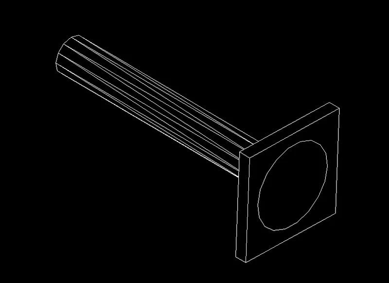
- created the 3D model of a drop column with panel in section and isometric view as shown in the figure.
- All dimension are in feet & inches.
AIM :- To create the 3D model of a wall as shown in figure.
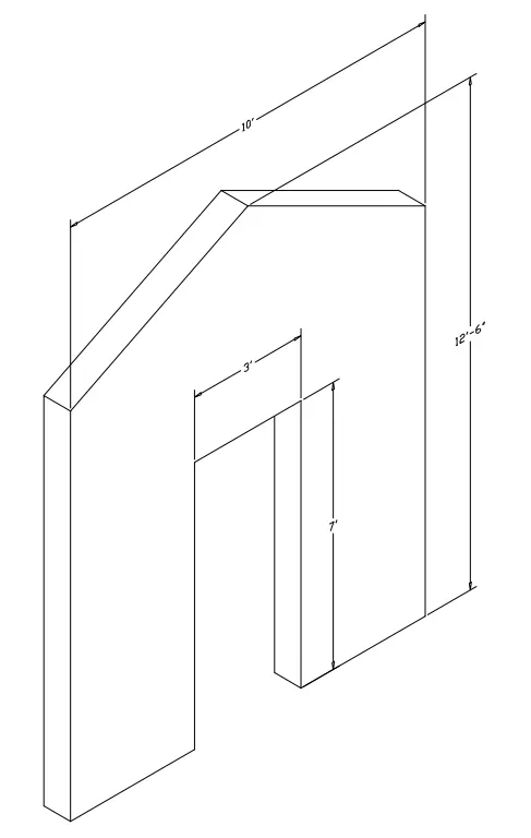
INTRODUCTION :- 3D model of the wall is created by using AutoCAD in 3D modelling workplace by using LINE command. The procedure of drawing is explained in details with each steps and the final result is given.
PROCEDURE :-
STEP 01.
- Go to START MENU select AutoCAD
- In Command prompt type STARTUP then enter
- Enter new value of startup as 1
- Go to application menu and select NEW
- Select IMPERIAL, then ok
- Type UNIT command
- In drawing unit dialog box select ENGINEERING
- In precision select 0’-0”
- INCHES in insertion scale then ok
- Select 3D Modelling from the workplace
- Set limits by entering LIMIT command
- Lower-left corner 0’0”,0’0” and upper-right corner 100’,100’
STEP 02.
- Type LINE in command prompt
- Specify first point : 0,0,0
- Specify next point : @0,0,-10’ enter
- Specify next point : @3’6’,0,0 enter
- Specify next point : @0,0,7’ enter
- Specify next point : @3’,0,0 enter
- Specify next point : @0,0,-7’ enter
- Specify next point : @3’6”,0,0 enter
- Specify next point : @0,0,10’ enter
- Again type LINE in command prompt
- Specify first point: Take middle of door
- Specify next point : 5’6” (z-axis)
- Now use LINE command to match line in both directions as shown
- Now use EXTRUDE command and extrude to height of 9”
STEP 03.
- Enter 3DFACE in command prompt
- Draw four point covering to other face enter
- Enter HIDE in command prompt
STEP 04.
- Enter DST command
- Click on Modify tab
- In Symbols and Arrows option change Arrow size to 3”
- In Text option change text height to 3”
- Then click OK then click on SET
- After that use DIMLINE command to show all dimensions
RESULT :-
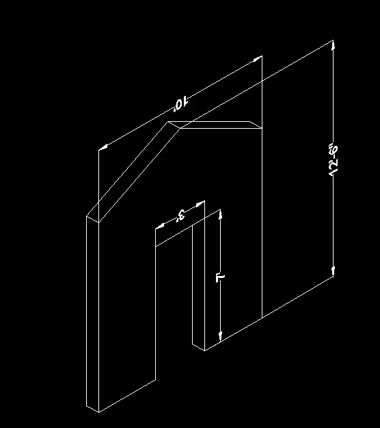
- 3D model of wall is created by using AutoCAD as shown in figure.
- All dimensions are in feet & inches.