Creating various 3D Models like Furniture, Footing, Girder, Column drop with panel and Gable Wall in AutoCad
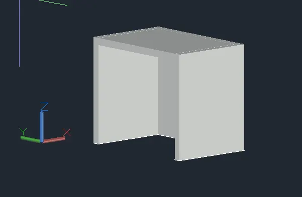
- To create a 3D Furniture element as shown in the Figure.
Introduction : For creating a 3D Furniture element follow the below steps Command to command.
Step 1: Starting with making lines by specifying distance on further directions so, give the
Command: L
LINE
Specify first point:
Specify next point or [Undo]: 2'
Specify next point or [Undo]: 3'
Specify next point or [Close/Undo]: 2'
Specify next point or [Close/Undo]: 2"
Specify next point or [Close/Undo]: 1'10"
Specify next point or [Close/Undo]: 2'8"
Specify next point or [Close/Undo]: 1'10"
Specify next point or [Close/Undo]: *Cancel*
Step 2: Extruding the object above at a distance of 2’6” so by,
Command: EXTRUDE
Specify height of extrusion or [Direction/Path/Taper angle/Expression]: 2'6"
Step 3: Drawing a rectangle above by Joining the two points so by command
RECTANG
Specify first corner point
Specify other corner point
Step 4: By command Extrude Extrude below the 2” to acquire the given figure
Command: EXTRUDE
Specify height of extrusion : 2”
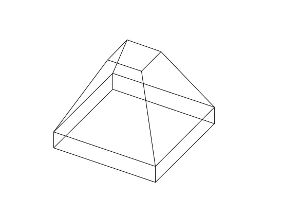
- Aim: To create the 3d Model of an Isolated footing as shown in Figure.
Introduction: For creating a 3D Furniture element follow the below steps Command to command.
Step 1: Draw a box by BOX command of length 2’X2’ and height of 6”
Step 2: Draw a rectangle by RECT command at center of the box to of length and width 1’X1’
Step 3: Move it on the z axis above 2’ height by Command MOVE
Step 5: By Line command LINE join the corner of the boxes to the corners of the rectangle to draw as same as figure.
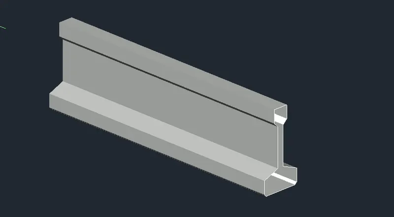
- Aim: To create the 3D view of the AASTHO Type Girder
Introduction: For creating a 3D Furniture element follow the below steps Command to command.
Command: L
LINE
Specify first point:
Specify next point or [Undo]: 1’4”
From each corner Draw a line of 1” at an angle of 135 and mirror it to make same as other side
At next
Command: L
LINE
Draw a line
Specify next point or [Undo]: 1’6”
Ortho on
Draw a line of height 6” ( straight line on both side facing above)
Ortho off
Draw a line at angle of 45 and distance is 6” on both sides and height is also 6”
Ortho on
Draw a line of 1’6” ( straight line on both side)
From each corner Draw a line of 1” at an angle of 135 and mirror it to make same as other side
Draw a line of height 6” ( straight line on both side facing above)
Close the line , figure
Command Extrude
Extrude the figure we have made at 10’
- To create a 3d Model of a drop column with panel as shown in section and isometric view.
Introduction: First we made a 2d model and then after draw a 3d isometric view
Step 1: Draw a rectangle of LXB (10’X1’6”)
Command RECTANGLE
Step 2: Draw a line of 1” height at angle of 135 and mirror it to draw as same at other side
Command used LINE, MIRROR
Step 3: Join the both corners by Using LINE command
Step 4: Draw a line of 1’ from both the corners
Step 5: Draw a line of 6” facing upwards and join both of the lines to acquire the 2d figure
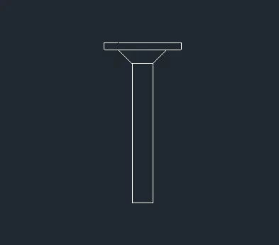
3D figure
Step 1: Draw a box of length 4’6”X4’6” and height 6” by using BOX command
Step 2: On the geometric center and draw a line from the center 10’ below
Step 3: Command EXTRUDE
Extruding by defining a path i.e line drawn to acquire the figure
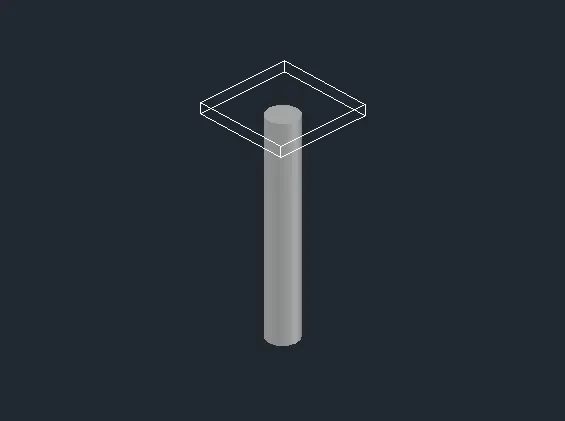
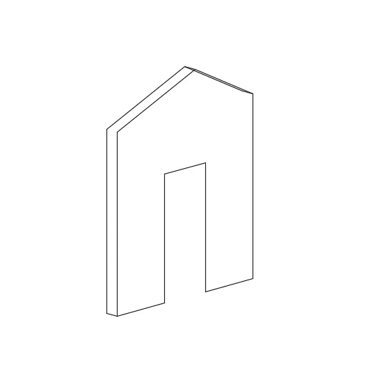
- To create the 3d model of a wall as shown in Figure
Introduction: Making a 3d model of a wall and Considering wall thickness as 9”.
Step 1: Draw a line of 3’6” by LINE command
Command: L
LINE
Specify first point:
Specify next point or [Undo]: 3’6” (Right)
Specify next point or [Undo]: 7’ (Above)
Specify next point or [Close/Undo]: 3’ (Right)
Specify next point or [Close/Undo]: 7’ (Below)
Specify next point or [Close/Undo]: 3’6” (Right)
Specify next point or [Close/Undo]: 10’ (Above)
Specify next point or [Close/Undo]: 10’ above from the first point
Specify next point or [Close/Undo]: *Cancel*
Step 2: Draw a taper of total height 12’6”
Step 3 : Draw the wall thickness by using LINE Command