Creating various 3D Models like Furniture, Footing, Girder, Column drop with panel and Gable Wall in AutoCad
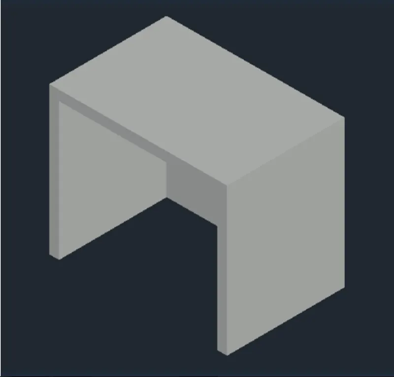
- Make a 3D Furniture element as given in the picture. Suppose dimensions which are absent.
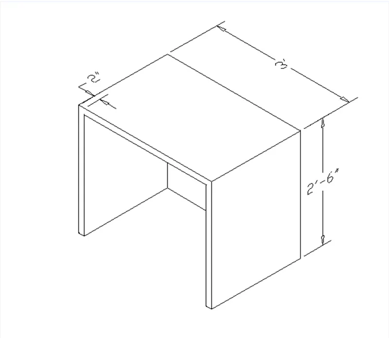
AIM: To make 3D model and view of.
- Furniture element.
- Isolated footing.
- AASTHO type girder.
- Drop column with panel
- A wall
INTRODUCTION:
- The three dimensional furniture elements were sketched in the AutoCAD utilizing the several tools in the AutoCAD.
- 3D models are widely utilized anywhere in 3D graphics and CAD.
- Their benefits predate the widespread benifits of 3D graphics on personal computers.
- The 3D models are preliminary preferable in the civil engineering and when we design a building in the AutoCAD then making 3d models should be must.
Command utilized:
- Line command
- UCS command
- Dim linear command
- Region command
- Extrude command
- Subtract command
- Box command
- Units command
- Dim style command
- 3D face command
- 3D orbit command
- Hide command
- Explode command
- Move command
- Copy command
- Dist command
PROCEDURE:
Step-1
- First we have to open the AutoCAD and require setting the units and dim style.
- Next we have to enter the UCS command and fix ucs icon on the screen.
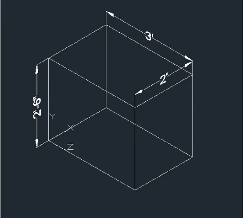
- After setting the ucs on the screen we require to sketch the line with the length of 3'.
- Next sketch the line from the previous line upwards with the length of 2'-6".
- Once more sketch the line from the previous line with the length of 3' horizontally.
- Next we sketch the line from the first line and last line to close the rectangle.
- Next we have to benifits the extrude command to extrude the rectangle towards back with the length of 2'.
Step-2
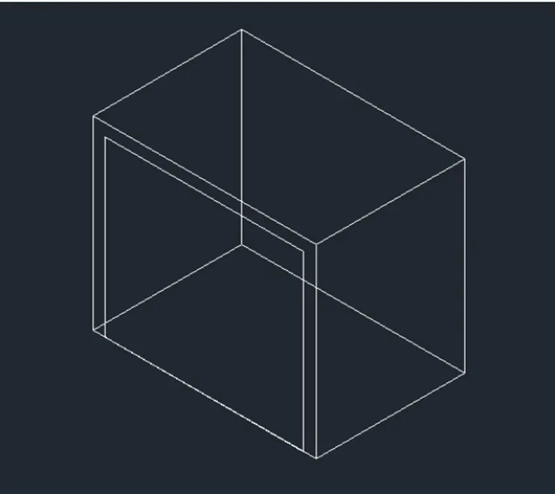
- Next we sketch the rectangle inside the extruded box as given in the below picture.
Step-3
- Next we have to extrude the inside rectangle with the length of 1'-10", as given in the below picture.
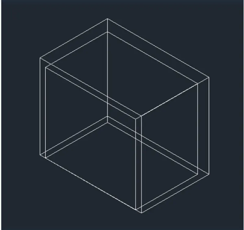
Step-4
- Next we subtract the inside box from the outer box utilizing the subtract command as given in the below picture.
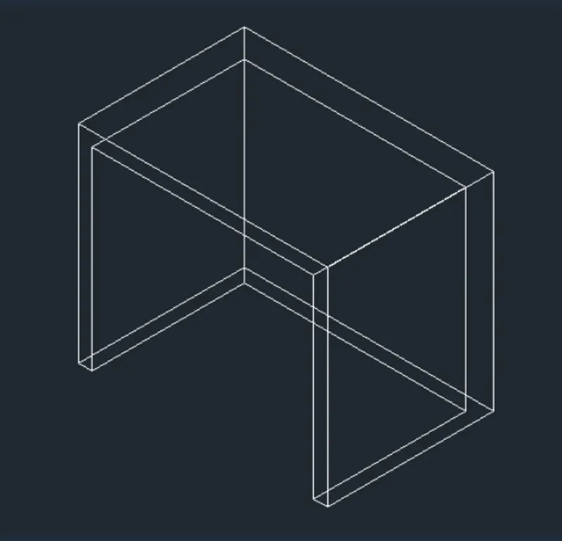
Step-5
- Next we have to benifits the 3D face command to hide the inner part, and also we benifits hide command to hide them as given in the below picture.
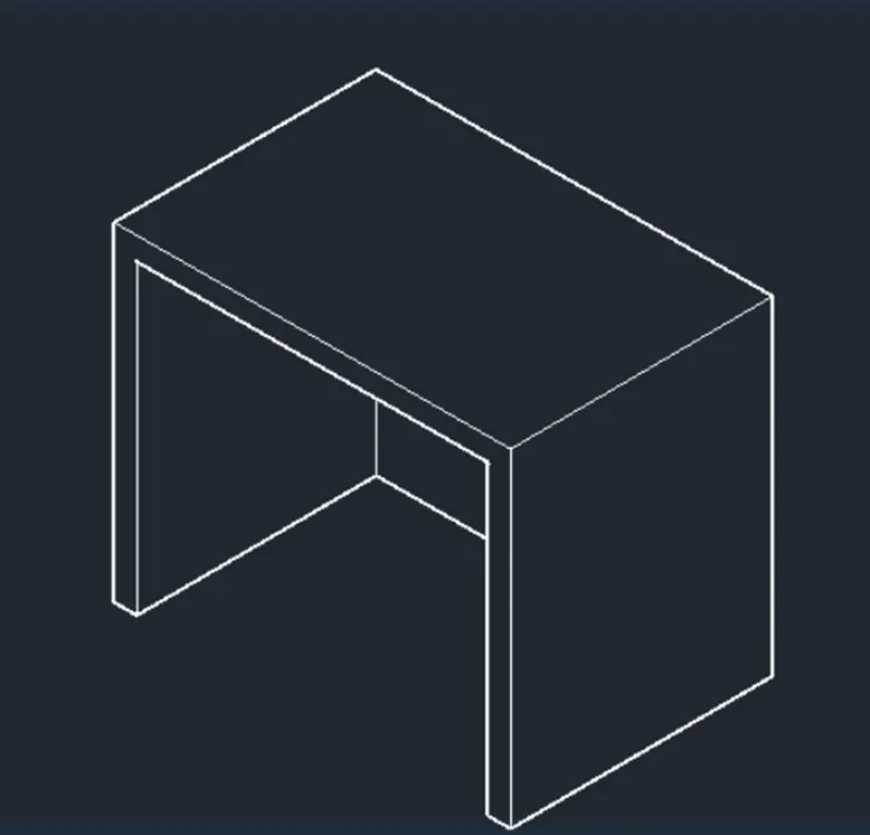
Step-6
- Next we put the dimensions for the every part in the sketching utilizing the dim linear command as given in the below picture.
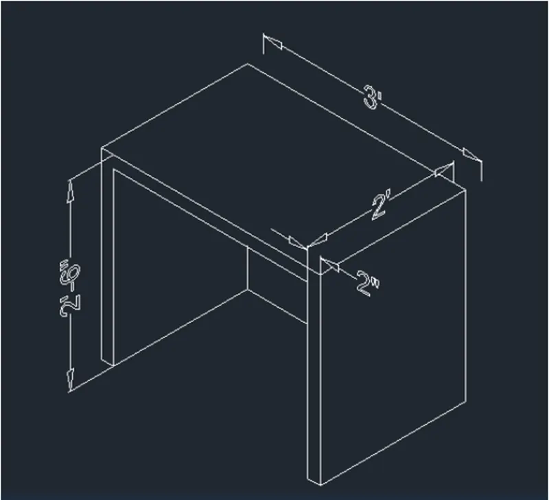
Step-7
- Next we click the custom visual styles at the top left corner of the sketching screen, and choose the shaded option in the custom visual styles.
RESULT:
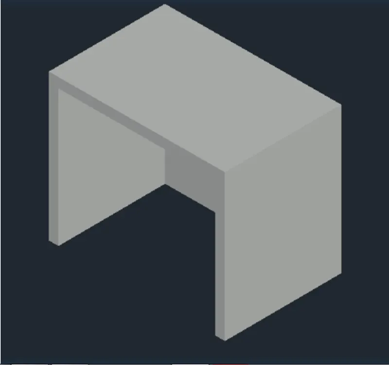
- Made the 3D model of the given furniture element with the proper dimensions in the auto cad in detail.
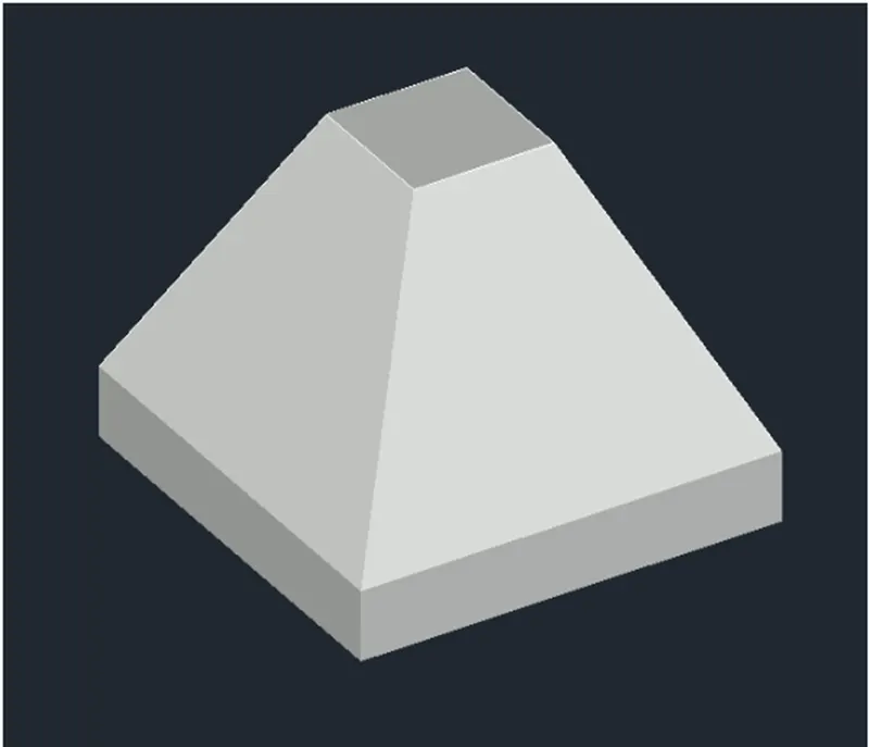
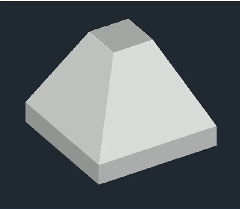
Q.2 Make the 3d Model of an isolated footing as given in Picture.
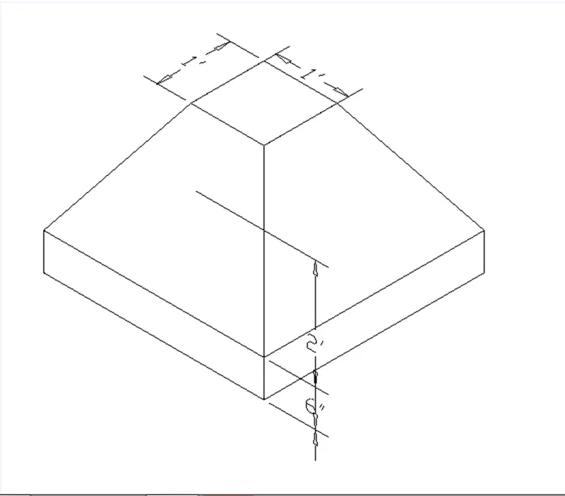
AIM: To make the 3D model of an isolated footing in the AutoCAD in detail.
INTRODUCTION:
- The three dimensional of isolated footing was sketchn in the AutoCAD utilizing the different tools in the AutoCAD.
- 3D models are widely utilized anywhere in 3D graphics and CAD.
- Their models are widely utilized anywhere in 3D graphics and CAD.
- The 3D models are mainly preferable in the civil engineering and when we design a building in the AutoCAD then making 3d models should be must.
Command utilized-
- Line command
- Rectangle command
- UCS command
- Dim linear command
- Region command
- Extrude command
- Subtract command
- Box command
- Units command
- Dim style command
- 3D face command
- 3D orbit command
- Hide command
- Explode command
- Move command
- Copy command
- Dist command
- Rule surf command
PROCEDURE:
Step-1
- First we have to open the AutoCAD and set the units utilizing the units command.
- Next choose the dim style command and choose primary units as architectural.
- Next we benifits the ucs command to set the directions of x-axis, y-axis and z-axis.
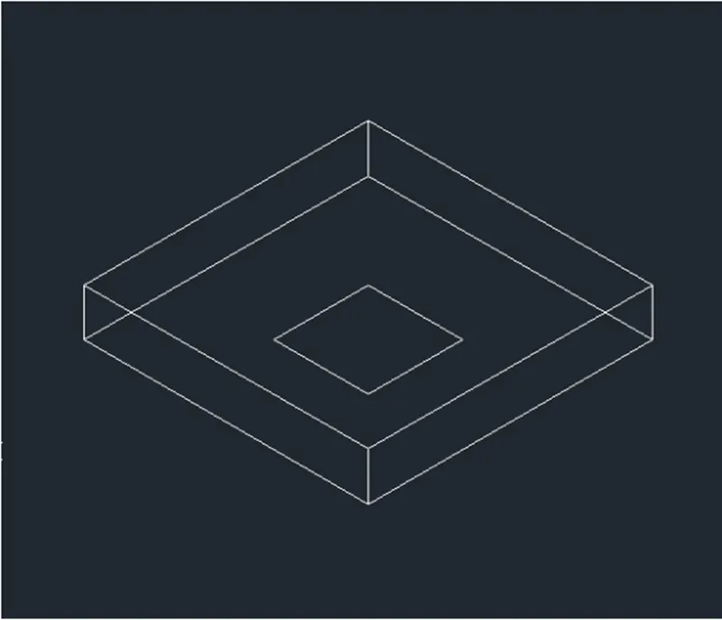
- Next we sketch the rectangle utilizing the line command with the size of 3' x 3'.
- Next we benifits extrude command to extrude the rectangle upwards with the length of 6".
- Next once more we sketch another rectangle at the center of the outer rectangle.
Step-2
- Next we benifits the move command to move the inner rectangle upwards with the length of 2'.
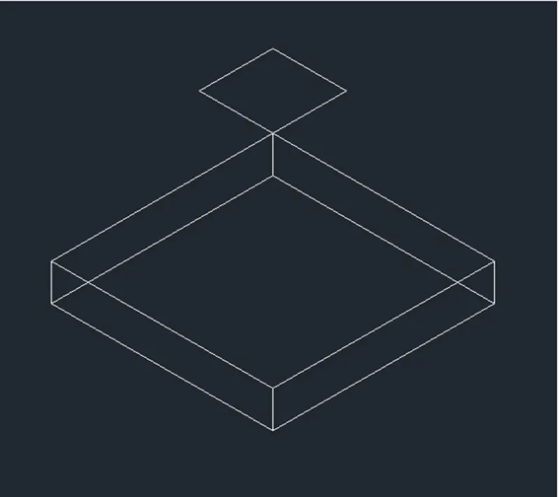
Step-3
- Next we benifits the Rule surf command to meet the 4 corners of the moved rectangle and four corners of extruded rectangle to co-ordinate each other.
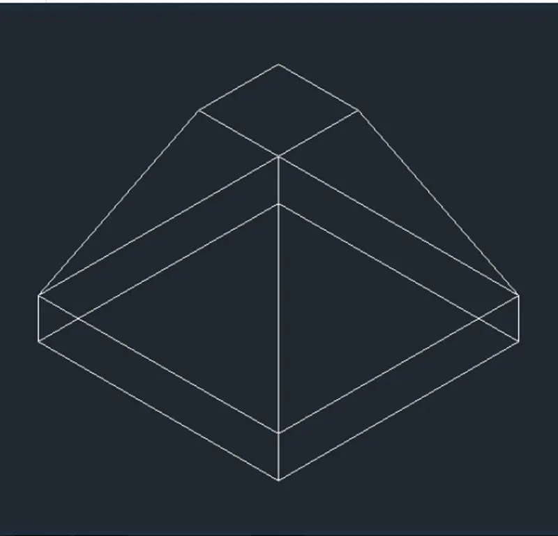
Step-4
- Next we require to benifits 3Dface command to visible as a 3d model as given in the picture.
- Next we benifits the hide command and thumbs enter, and then we benifits to choose the four corners of every part in the sketching.
- After chooseing the four corners of every part in the sketching and then thumb enter, the lines detectable in the part will hide naturally after pressing the enter.
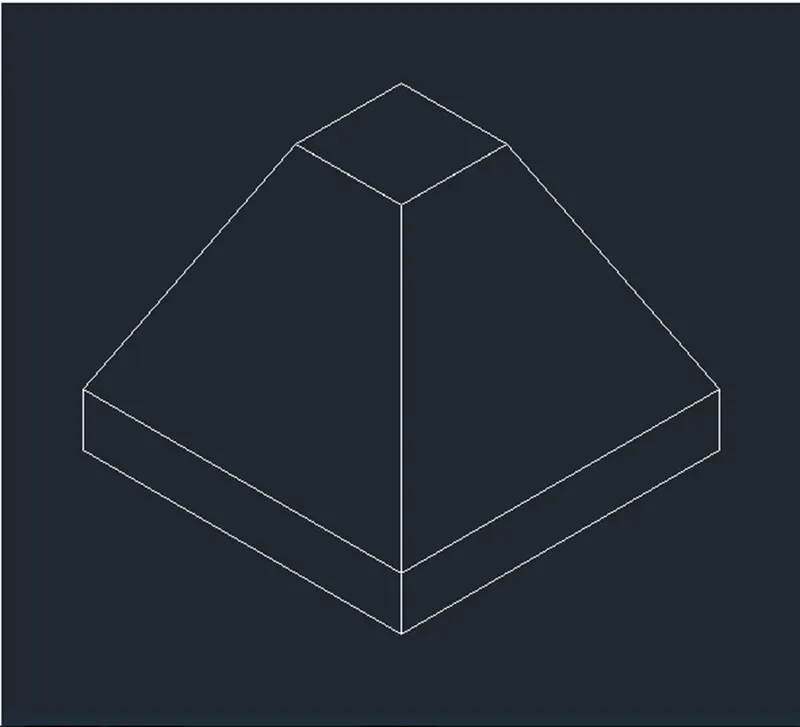
Step-5
- Next we require to put the dimensions for every part in the sketching as given in the below picture.
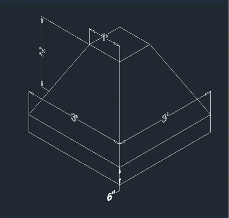
Step-6
- Next we click the custom visual styles at the top left corner of the sketching screen, and choose the shaded option in the custom visual styles.
RESULT:
- The given 3D model of the isolated footing is sketchn successfully in the AutoCAD in detail.
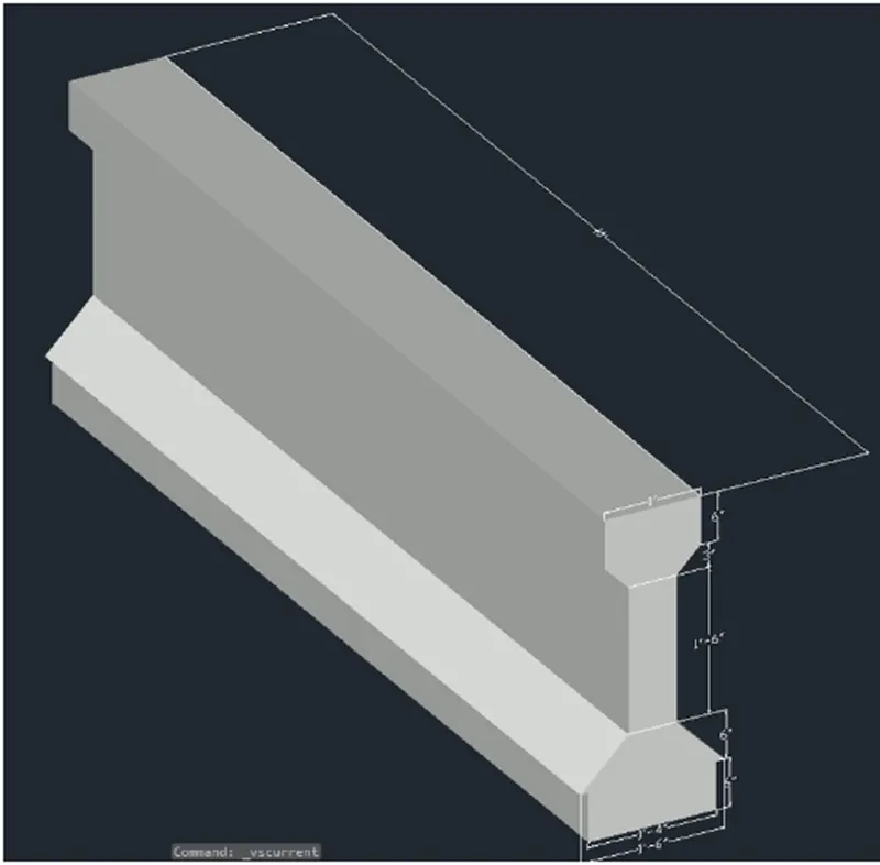
Q3. Make the 3D view of the AASTHO Type Girder.
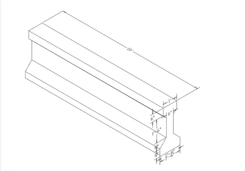
AIM: To make the 3D model of AASTHO Type Girder in the AutoCAD in detail.
INTRODUCTION:
- The three dimensional of AASTRO Type Girder was sketchn in the AutoCAD utilizing the different tools in the AutoCAD.
- 3D models are widely utilized anywhere in 3D graphics and CAD.
- Their benefit predates the widespread benefits of 3D graphics on personal computers.
- The 3d models are mainly preferable in the civil engineering and when we design a building in the AutoCAD then making 3d models should be must.
Command utilized:
- Line command
- Rectangle command
- UCS command
- Dim linear command
- Region command
- Extrude command
- Subtract command
- Box command
- Units command
- Dim style command
- 3D face command
- 3D orbit command
- Hide command
- Explode command
- Move command
- Copy command
- Dist command
- Rule surf command
- Plan command
PROCEDURE:
Step-1
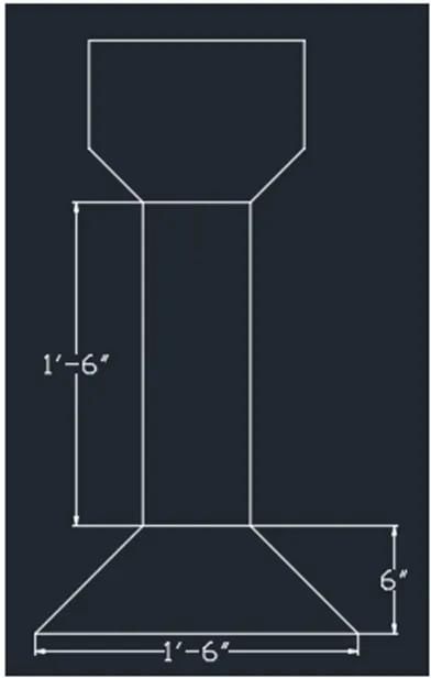
Click on front view. Benefits UCS command and make the x and y axis in the front view plane.
Step-2
Then by line command sketch the I section with the given dimension. Command 'L”, sketch a line of 1' that is the top width of the girder.
With the line sketch a 6" downwards. With snap on sketch a line from the center of 1' and offset 3" on both sides such that the width of web becomes 6".
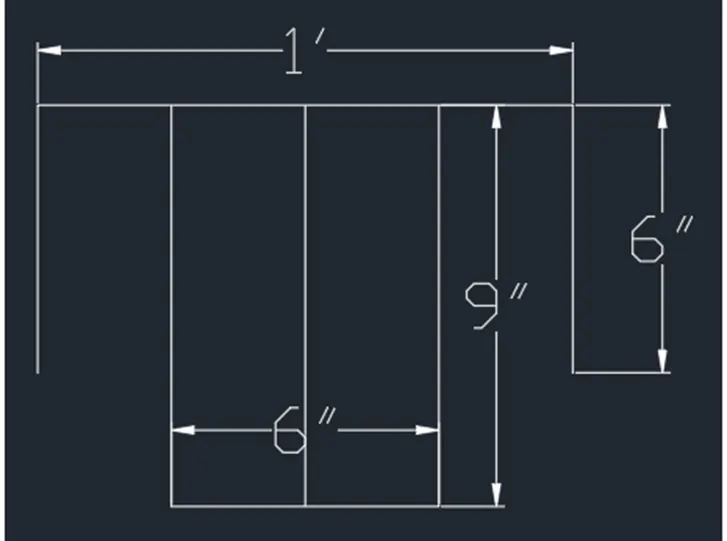
Step-3
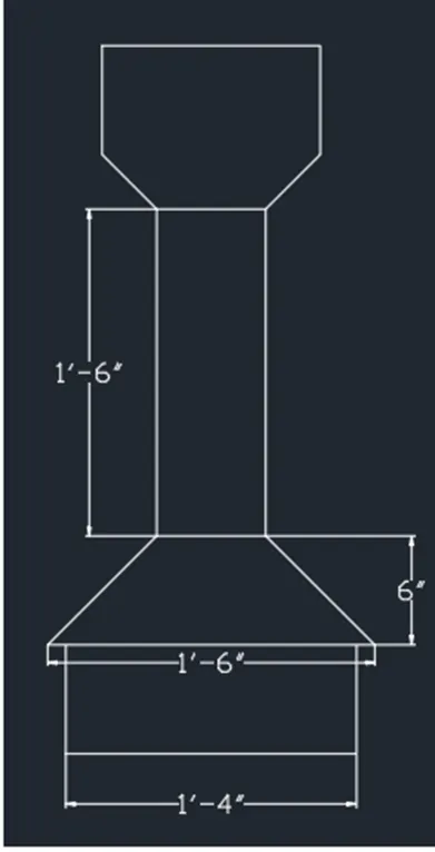
Give a taper distance and meet the web and the flange. Mirror the same on the other side the web is given a height of 1'6", offset the distance 1'6"from the end of tapering of the flange portion (1').Delete the center line sketchn for the offset and also trim off the extra lines in flange.
Step-4
Extend the web to the offsite line. Once more offset 6" from the last line and taper the sides. Mirror the tapered portion to the other side. The sides should be tapered such that the bottom should be 1'6", sketch a center line and offset 9" on both sides, then meet the taper.
Step-5
Offset 6" downwards from the bottom horizontal line to define the height. To sketch the taper at bottom 1'4”, from the Centre sketch a line and offset 8" on both sides.
Step-6
Extend the 6" offsite line and trim the rest of lines. Sketch the vertical line downwards and the tapering also.
Step-7
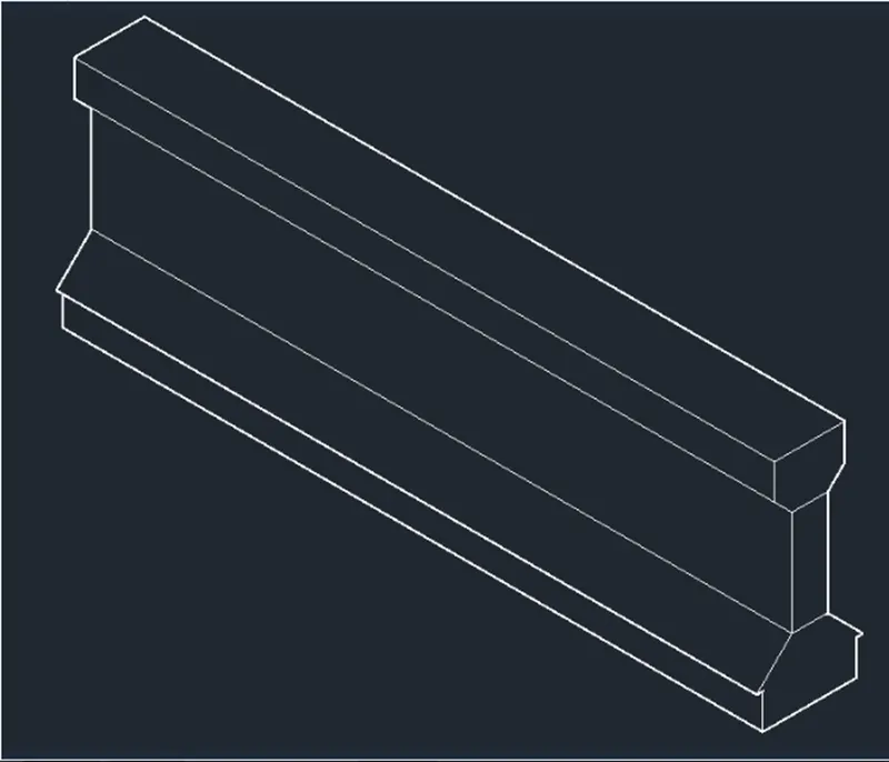
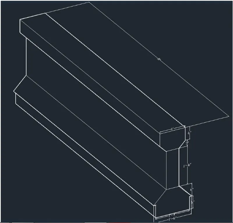
With 3d orbit turn the view and sketch a line of 10' in z direction. Click on sweep from the home toolbar and choose the section and, then the path through which the section to be swept i.e., the line.
RESULT:
The 3D model of the AASTHO girder is sketched.
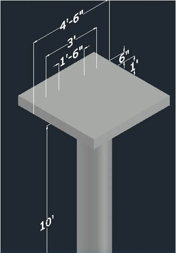
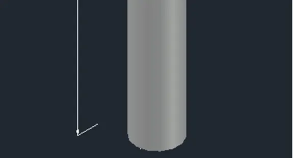
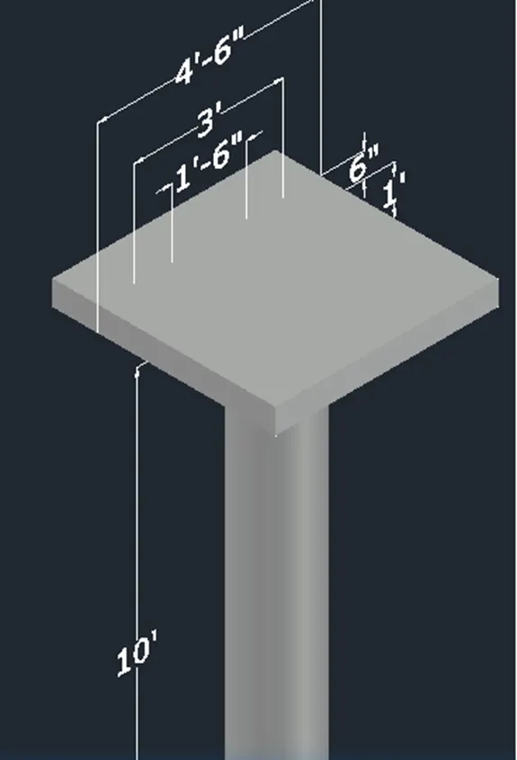
Q.4 Make a 3d Model of a drop column with panel as given in section and isometric view.
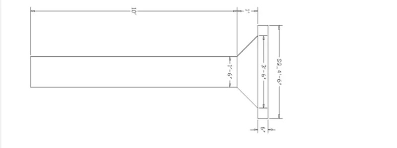
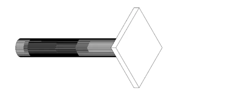
AIM: To sketch the 3d model of a drop column with panel section and show its isometric view.
INTRODUCTION:
- The three dimensional of Drop column with panel was sketched in the AutoCAD utilizing the different tools in the AutoCAD.
- 3D models are widely utilized anywhere in 3D graphics and CAD.
- Their benefits predate the widespread benefits of 3D graphics on personal computers.
- The 3d models are mainly preferable in the civil engineering and when we design a building in the AutoCAD then making 3d models should be must.
Command utilized:
- Line command
- Rectangle command
- UCS command
- Dim linear command
- Region command
- Extrude command
- Subtract command
- Box command
- Units command
- Dim style command
- 3Dface command
- 3D orbit command
- Hide command
- Explode command
- Move command
- Copy command
- Dist command
- Rule surf command
- Plan command
PROCEDURE:
Step-1
- Make a circle of diameter 1'6” in the top view.
Step-2
Make a region-by-region command and choose the rectangle. Extrude it with extrude in home toolbar and provide a distance of 10'.
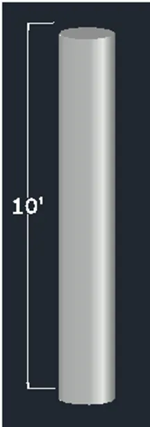
Step-3
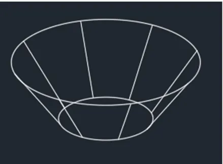
- Make a cone by clicking on cone from the home toolbar. Click on diameter and provide the base diameter as 1'6".
Step-4
- Click on top radius and give the value as 1'6" and provide the height of the cone as 1".
Step-5
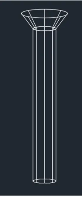
Place the frustum of cone on top of the extruded circle i.e. the column in the front view, with snap option place such that the center of two objects coincide ,also put the center of frustum with center of column in the top view.
Step-6
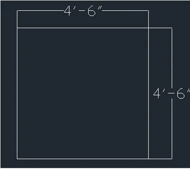
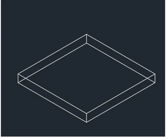
- In top view, make a rectangle of dimension 4'6" x4'6". Extrude it to a height of 6".
Step-7
- In the top view, place the rectangle at the center of cone and also fix in the front view or give move command and provide the coordinate as 0,10',0 as the rectangle is at bottom in the front view.
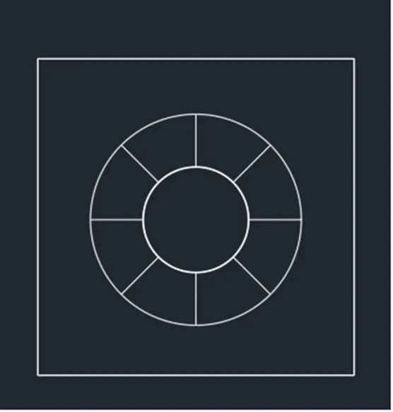
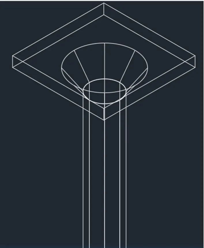
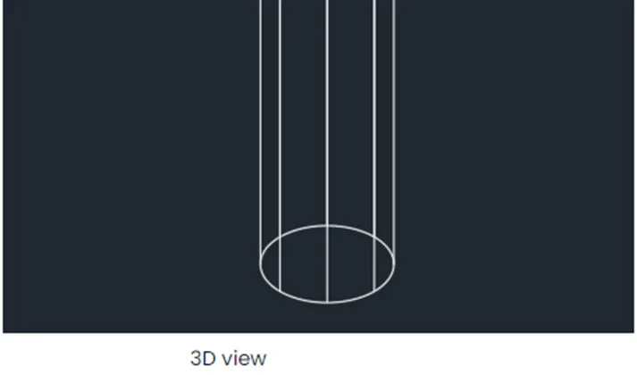
RESULT:
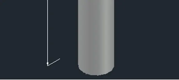
The 3d model of a drop column with panel has been sketched section and isometric view is also given.
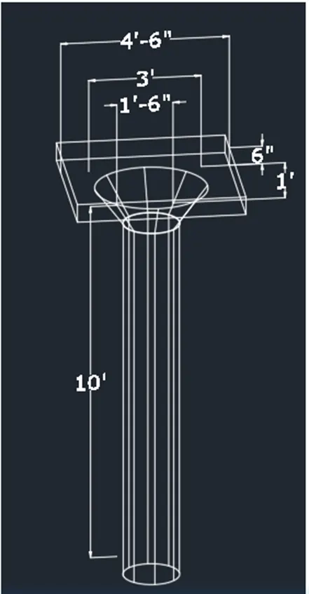
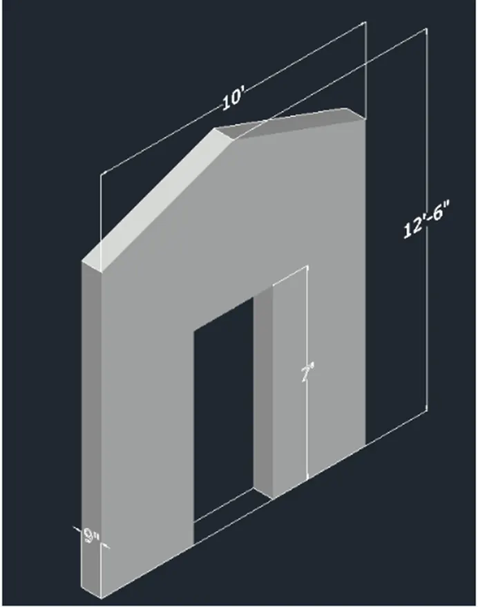
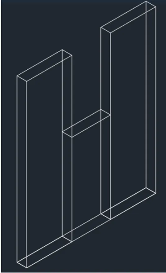
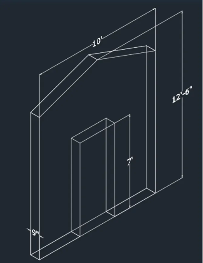
- Make the 3d model of a wall as given in Picture. Consider wall thickness as 9”.
AIM: To sketch a 3d model of wall.
PROCEDURE:
Step-1
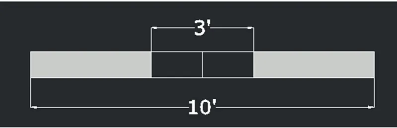
- Sketch a rectangle of 10' x 9".Make a line in the center and offset 1.5" on both sides as 3" is the width of door opening.
Step-2
- Benefits the command "BO" for boundary and make the region i.e., both the region on either side of the door opening.
Step-3
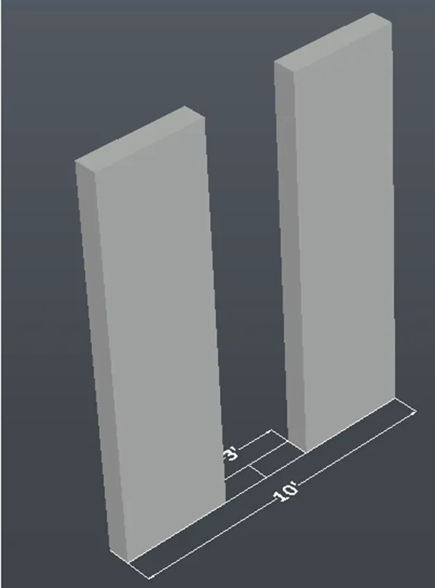
- Extrude the region to a height of 12'6" total height.
Step-4
- Make a rectangle in place of door in the top view. Move the rectangle in z axis at a height of 7' from the bottom.
Step-5
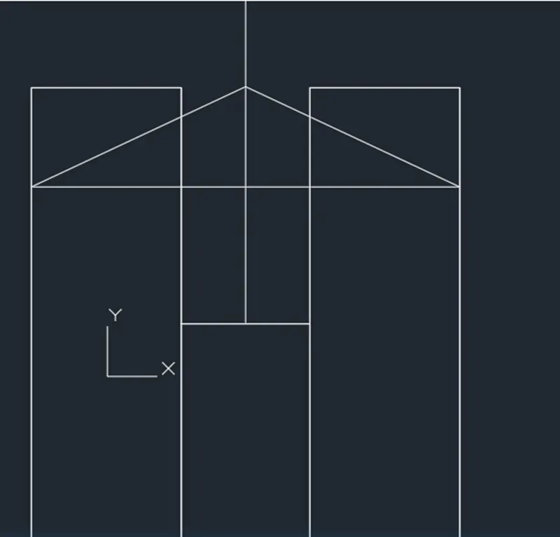
- Go to front view and sketch a line from the center of the moved line of door. Sketch slanting line from the total height from the center line intersecting the edge.
Step-6
- Mirror the line to the other side. Sketch the horizontal line to meet.
Step-7
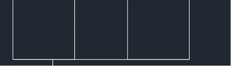
Trim off the excess line and the center line and meet the triangle with meet command. Make a region with region command in the triangle made.
Step-8
Choose the extruded rectangle and with the help of grip bring it down to the level of the triangle base on both sided. Extrude the rectangle of door to a height equal to base of triangle.

RESULT:
3D model of wall is sketched.
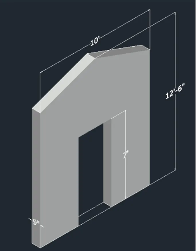
RESULT:
3D model of furniture element is made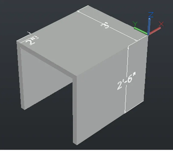 3D model of isolated footing is made
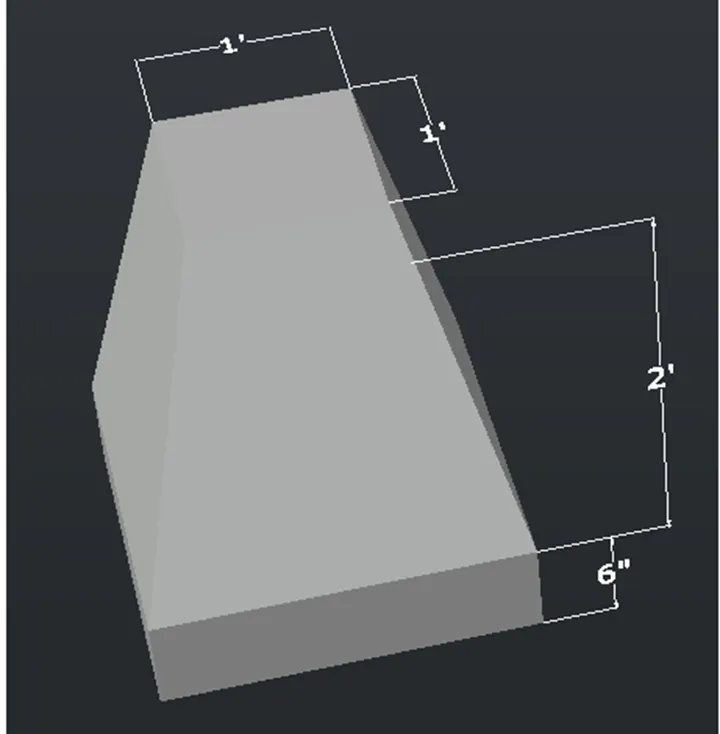 3D model of AASTHO type girder is made
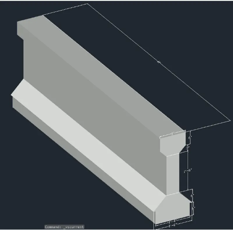 Drop column with panel 3D model is made.
 3D model of wall is made