Creating various 3D Models like Furniture, Footing, Girder, Column drop with panel and Gable Wall in AutoCad
Question 1. Create a 3D Furniture element as shown in the Figure. Assume dimensions which are missing.
AIM: To create the 3D furniture elements.
INTRODUCTION: AutoCAD allows the user to create the 3D objects in the software. In this question we will be learning about the isometric view of the elements in a detailed manner. The detailed procedure is given below step-by-step.
PROCEDURE:
- In order to create the 3D or isometric views in the AutoCAD software first we need to go to the AutoCAD software. Just open the AutoCAD software.
- Open the new file in the software.
- After opening to the new file set the units as the Architecture,change the units as feets and inches and the precision as 0'-0". And then press OK.
- Now set the limits as 10000',10000'.
- Now after setting the units and the limits,just change the workspace setting because we want to draw the isometric view in the workspace.
- So change the workspace setting as 3D workspace with drafting and the annotation.
- To change the workspace setting go to the right bottom of the AutoCAD software there is an option called setting from that there is an option called 3D modelling click on that option, then your space as 3D modelling have been created as shown in the below figure:

- So in order to create the 3D furniture element as shown in the figure.Firstly we have to draw the frame.
- And to draw the frame we have to use the line command.
- And to use the line command we need to type L in the command line and then press Enter.
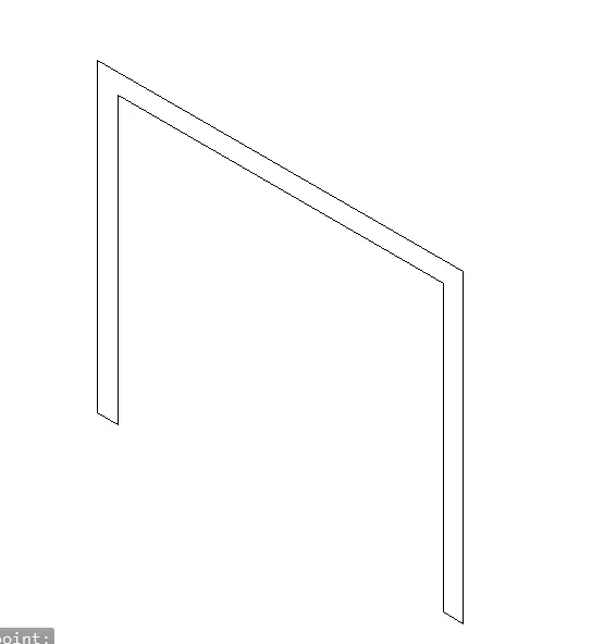
- Now draw the frame of the 3D furniture.
- Draw a vertical line of 2'-6" and the horizontal line of 3'. And draw the depth of the frame as 2" as shown in the below figure:
- Now the framework is ready.
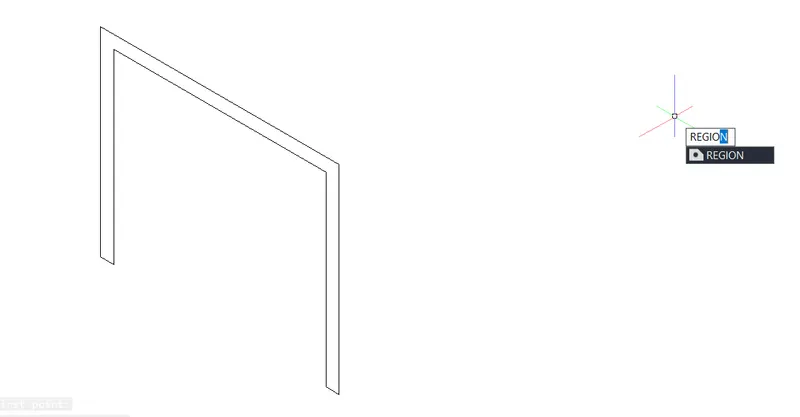
- Now we will be using here region command in order to make these different elements as one element.
- For doing so we have to just type REGION in the command line and then press Enter as shown in the below figure:
- Now the different elements are one element now.
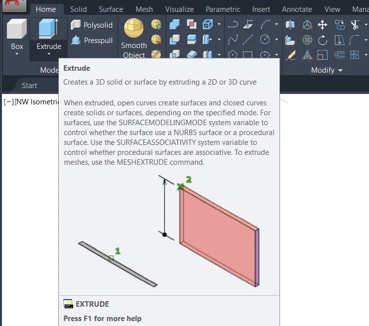
- After that we will be using the EXTRUDE command in order to extrude the element.
- To provoke the EXTRUDE command we need to go to the Home tab, in home tab there is an option called Extrude just click on that option just as shown in the below figure:
- Now use the extrude command to extrude the frame upto a certain depth.
- Now after clicking on the option EXTRUDE from the home tab,now it will ask us to select the object which we want to extrude.
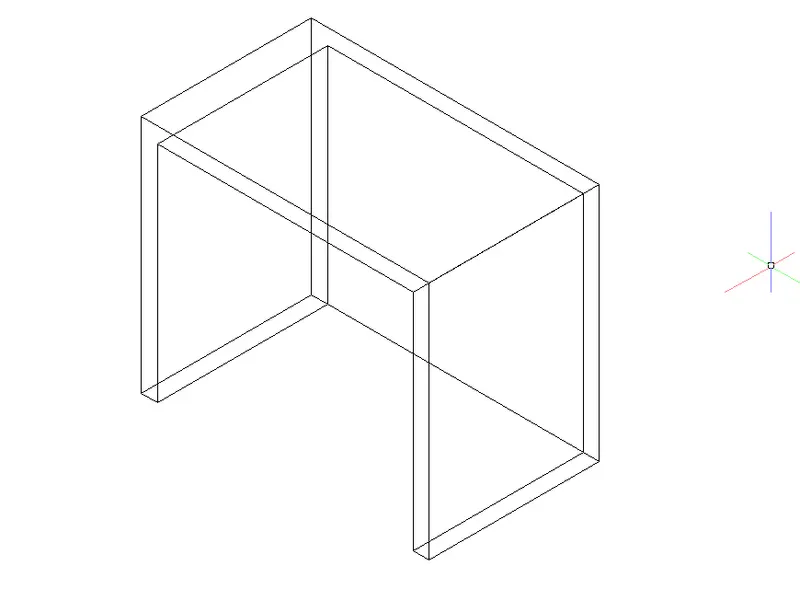
- So select the whole frame to extrude and give it a depth of 1'-9".
- Use the line command to join the bottom of the frame.
- Now the frame have been extruded as shown in the below figure:
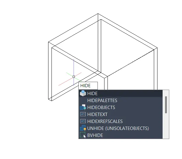
- After extruding the frame we need to hide the extra wireframe that are visible.
- In order to do that we will be using the HIDE command.
- To invoke the Hide command just type HIDE in the command line and then press Enter as shown in the below figure:
- Now the extra wireframe is hidden as shown in the below figure:
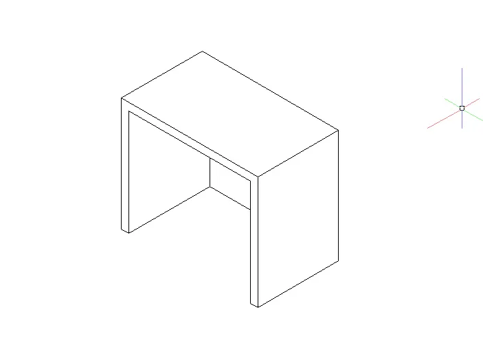
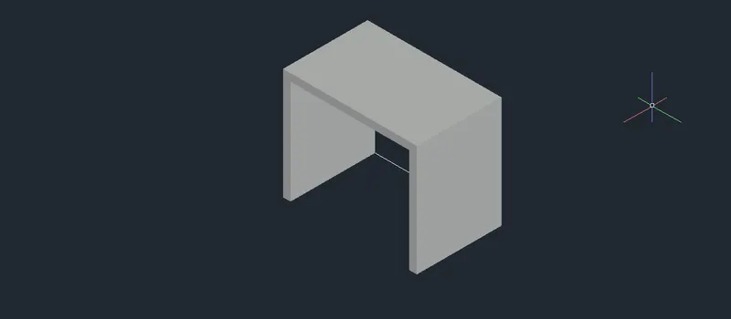
- The 3D furniture Element is ready. Now change the view to the REALISTIC,to see the realistic solid 3D model as shown in the below image:
Question2. Create the 3d Model of an Isolated footing as shown in Figure.
AIM: To create the 3D Model of an Isolated footing.
INTRODUCTION: AutoCAD allows the user to create the 3D objects in the software. In this question we will be learning about the isometric view of the elements in a detailed manner. The detailed procedure is given below step-by-step.
PROCEDURE:
- In order to create the 3D or isometric views in the AutoCAD software first we need to go to the AutoCAD software. Just open the AutoCAD software.
- Open the new file in the software.
- After opening to the new file set the units as the Architecture,change the units as feets and inches and the precision as 0'-0". And then press OK.
- Now set the limits as 10000',10000'.
- Now after setting the units and the limits,just change the workspace setting because we want to draw the isometric view in the workspace.
- So change the workspace setting as 3D workspace with drafting and the annotation.
- To change the workspace setting go to the right bottom of the AutoCAD software there is an option called setting from that there is an option called 3D modelling click on that option, then your space as 3D modelling have been created as shown in the below figure:
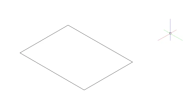
- In order to create a 3D Model of an Isolated footing. First of all we need to draw a rectangle of 4' using the rectangle command.
- To use the rectangle command just type REC in the command line and then press Enter.
- Now draw a rectangle of 3'X3'.
- Specify the first point in the drawing sheet.
- Now type d in the command line and then press enter.
- Now give the dimensions as 3'X3' , rectangle is ready as shown in the below figure:
- Now copy that rectangle in the upward z direction of distance 6" as shown in the below figure:
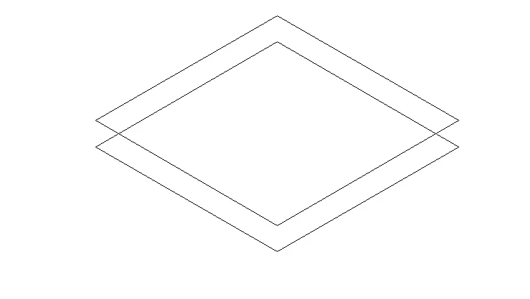
- Now similarly draw another rectangle of 1'X1' and move it with the help of the move command.
- Select the smaller rectangle give the move command just type MOV in the command line and then press Enter.
- Select the square,centre as its base point and move it to the centre of the upper large square.
- Now again move the smaller square in the z-direction upto 2' in the upward direction as shown in the below figure:
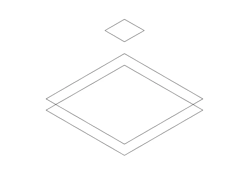
- Now using the line command join the edges of the square.
- To use the line command just type L in the command line and then press Enter.
- Now join the edges as shown in the below image:
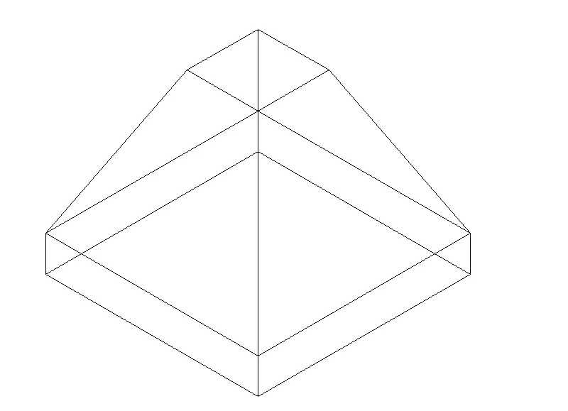
- Now use the hide command to hide the extra wireframe that are visible.
- In order to do that we will be using the HIDE command.
- To invoke the Hide command just type HIDE in the command line and then press Enter as shown in the below figure:
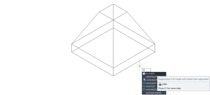
- The extra wireframe is hidden now as shown in the below figure:
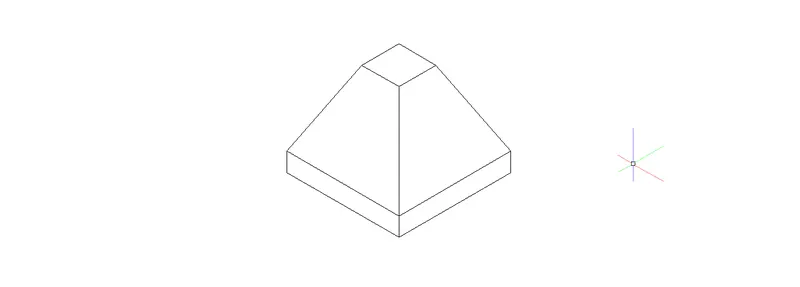
Question3. Create the 3D view of the AASTHO Type Girder.
AIM: To create the 3D view of AASTHO Type Girder.
INTRODUCTION: AutoCAD allows the user to create the 3D objects in the software. In this question we will be learning about the isometric view of the elements in a detailed manner. The detailed procedure is given below step-by-step.
PROCEDURE:
- In order to create the 3D or isometric views in the AutoCAD software first we need to go to the AutoCAD software. Just open the AutoCAD software.
- Open the new file in the software.
- After opening to the new file set the units as the Architecture,change the units as feets and inches and the precision as 0'-0". And then press OK.
- Now set the limits as 10000',10000'.
- Now after setting the units and the limits,just change the workspace setting because we want to draw the isometric view in the workspace.
- So change the workspace setting as 3D workspace with drafting and the annotation.
- To change the workspace setting go to the right bottom of the AutoCAD software there is an option called setting from that there is an option called 3D modelling click on that option, then your space as 3D modelling have been created as shown in the below figure:
- In order to create the 3D view of the AASTHO Type Girder we first need to create the I section.
- So in order to create the I section we need to use the line command with the help of the line command we can draw the I section.
- To use the line command just type L in the command line and then press Enter.
- First draw a line of width 6" in the positive Z-Direction and then draw another line of 6" in X-direction another line of 1'-6" in the positive Z-direction and then another line of 3" in the negative Y-direction. Then a line of 6" in the upward direction and a line of 1' in the positive X-direction and then create the other half of the I section using the same procedure and the same dimensions on the other side also.
- Now the I section have been created as shown in the below figure:
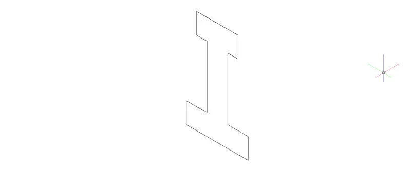
- Now we have to create the edges by using the another command CHAMFER.
- So to use the chamfer command just type CHA in the command line and then press Enter.
- So this is how we can chamfer the edges of the I-Section using the chamfer command . Just as shown in the below figure:
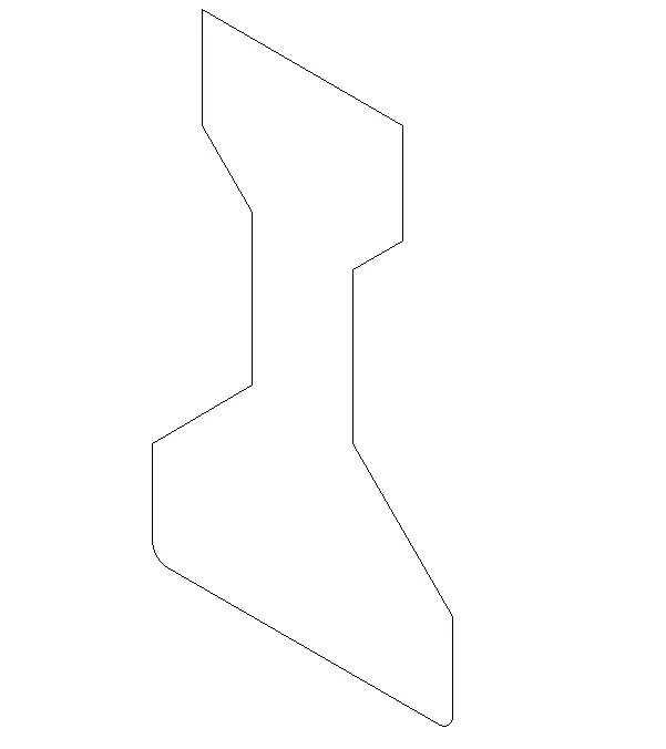
- Now after chamfering the edges of the I-section, now we need to use the region command to make it as a REGION.
- So in order to use the Region command just type REG in the command line and then press Enter.
- Now the I-section is one element after using the region command. As shown in the below figure:
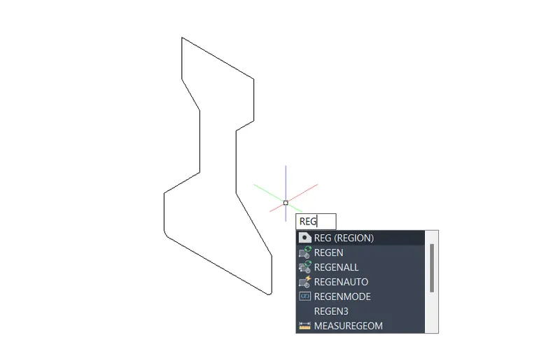
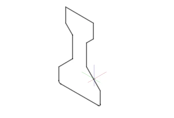
- Now after using the Region command,if we select the single then the whole I section has been selected because we have just use the Region command as shown in the above figure.
- Now after this, we have to do the extrution, and to use the Extrude command we need to just type Ext in the command line and then press Enter as shown in the below image:
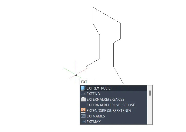
- Now the extrude command have been invoked. so do the extrution of the I section upto the 10' as shown in the below figure:
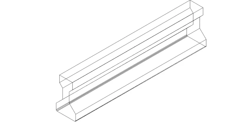
- Now use the hide command to hide the extra wireframe,just type HI in the command line and then press Enter.
- All the extra wireframe or extra lines are hidden by using the hide command as shown in the below image:
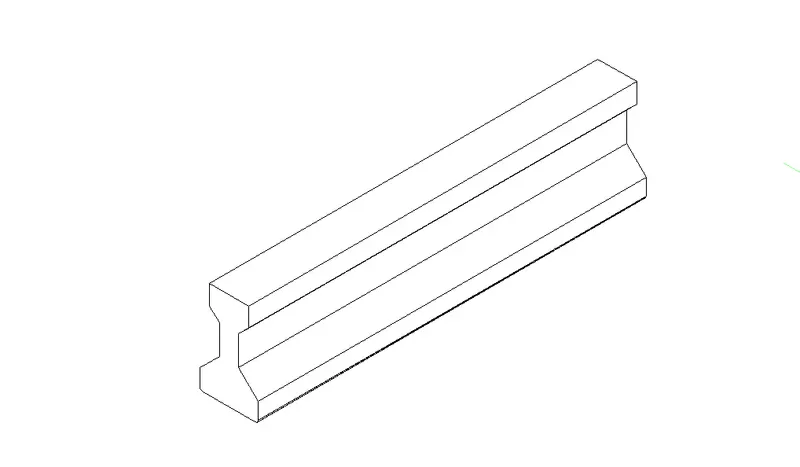
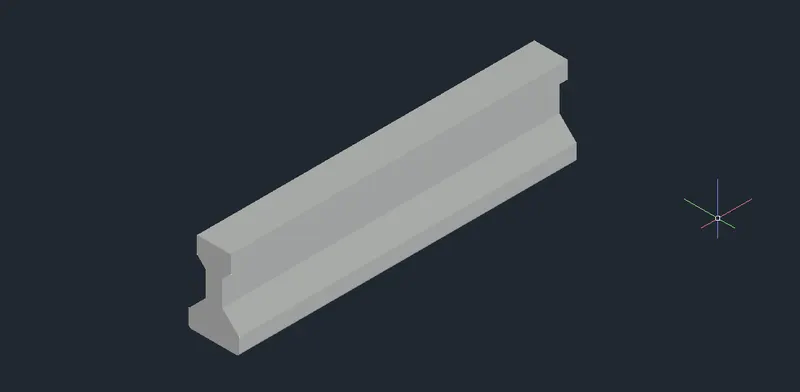
- Now change the view to the Shaded/Realistic view to see the Solid 3D model as shown in the below figure:
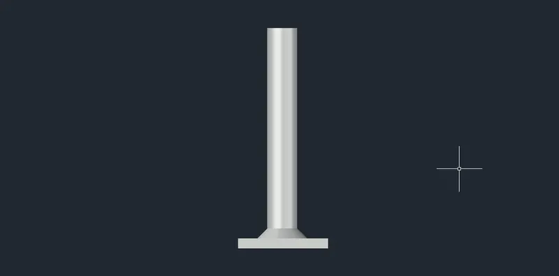
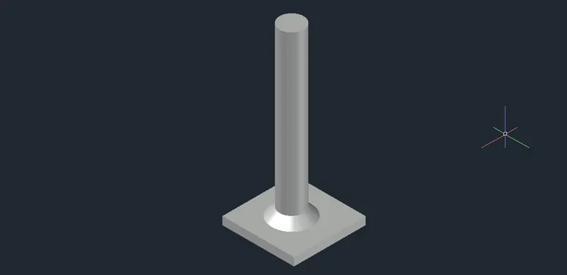
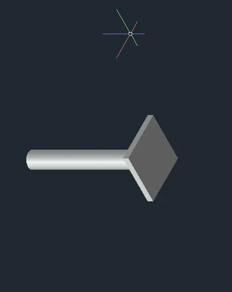
Question4. Create a 3d Model of a drop column with panel as shown in section and isometric view.
AIM: To create the 3D Model of a drop column with panel as shown in section and isometric view. .
INTRODUCTION: AutoCAD allows the user to create the 3D objects in the software. In this question we will be learning about the isometric view of the elements in a detailed manner. The detailed procedure is given below step-by-step.
PROCEDURE:
- In order to create the 3D or isometric views in the AutoCAD software first we need to go to the AutoCAD software. Just open the AutoCAD software.
- Open the new file in the software.
- After opening to the new file set the units as the Architecture,change the units as feets and inches and the precision as 0'-0". And then press OK.
- Now set the limits as 10000',10000'.
- Now after setting the units and the limits,just change the workspace setting because we want to draw the isometric view in the workspace.
- So change the workspace setting as 3D workspace with drafting and the annotation.
- To change the workspace setting go to the right bottom of the AutoCAD software there is an option called setting from that there is an option called 3D modelling click on that option, then your space as 3D modelling have been created as shown in the below figure:
- In order to create the 3D Model of a drop column with panel first of all we have to draw the the panel.
- So in case of drawing the panel we first have to draw the rectangle.
- To draw the rectangle we need to use the rectangle command.
- In order to use the rectangle command just type REC in the command line and then just press Enter.
- Then specify the first corner and then type d in the command line and then give the dimensions.
- Draw a rectangle of 4'-6" just as shown in the below figure:
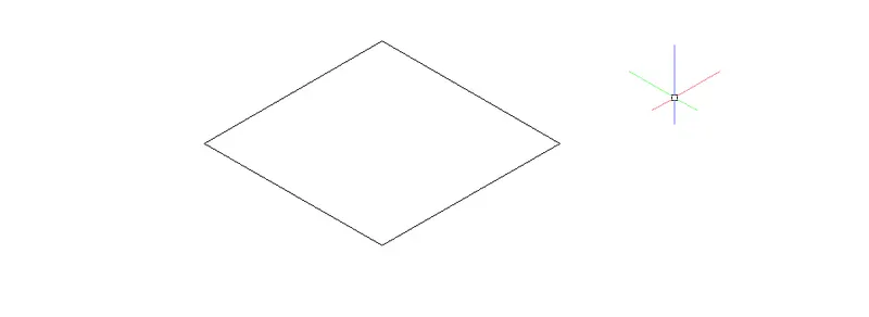
- After creating the rectangle,use the extrude command to extrude this rectangle upto a depth of 6".
- To use the extrude command go to the Home tab there is an option called extrude click on that option and extrude the rectangle upto 6". Just as shown in the below figure:
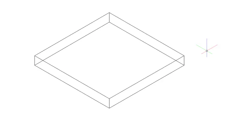
- Now after extruding the circle,now use the circle command to draw the circle.
- To invoke the circle command just type C in the command line and then press Enter.
- Now draw a circle using the circle command.
- Specify the centre of the circle, now choose the option diameter and now give the diameter as 3'-6" .
- The circle of diameter 3'-6" is ready.
- Now draw another circle of diameter 1'6". Draw this circle with the same procedure as we draw the bigger circle.
- Now after creating both the circle we will be using the option Loft to create the extrusion of the smaller circle.
- We can use this command,just go to the home tab there is an option called Extrution in that there are many options in that there is an option called Loft just click on that as shown in the below figure:
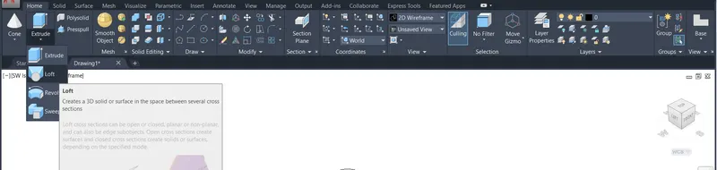
- After selecting the Loft option create the extrtion for the smaller circle.
- After extruting the smaller circle the circles will look like as the below image:
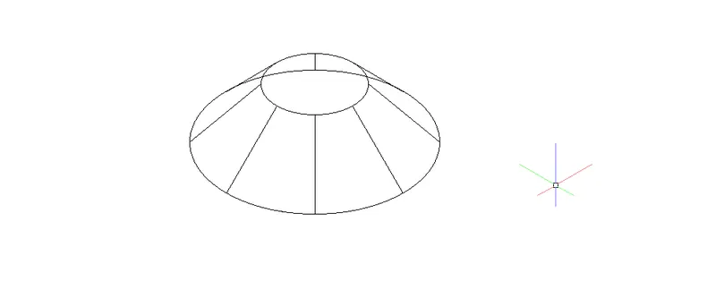
- Now use the move command to move this object.
- Just type MOV in the command line and then press Enter.
- Select the centre as the base point for the circle now move the circle over the rectangular pannel.
- Take it the centre of the rectangle as the base point and then click on that now this cone moved to the rectangular pannel.
- Now we have to create the panel.
- In order to create the pannel first we have to draw a circle of diameter 1'-6".
- And to draw a circle we need to type C in the command line and then press Enter.
- Specify the centre point for the circle and choose the option diameter.
- Then give the diamensions as 1'-6", now the circle have been ready.
- After creating a circle of diameter 1'-6" we have to use the extrution command, to use the extrution command just go to the home tab and there is an option called Extrution just click on that option.
- Now select the circle which we want to extrude.
- Now give the depth of 10' and then extrude the circle as shown in the below figure:
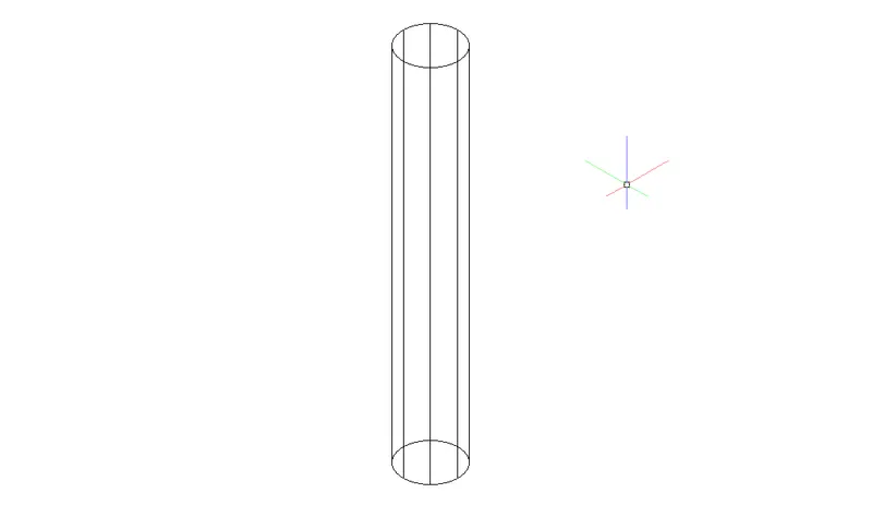
- Now again use the Move command to move this pannel onto the rectangular pannel.
- To use the move command just type MOV in the command line and then press Enter.
- Specify the base point as the centre of the circle and move the object as shown in the below figure:
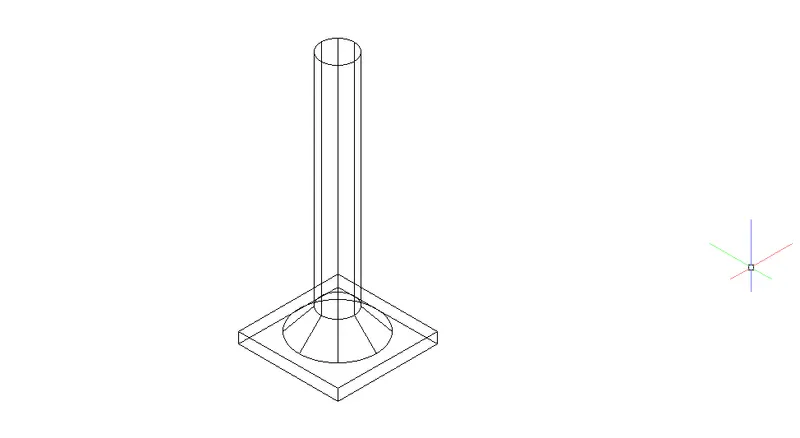
- Now change the view to the Shaded/Realistic view to see the Solid 3D model as shown in the below figure:
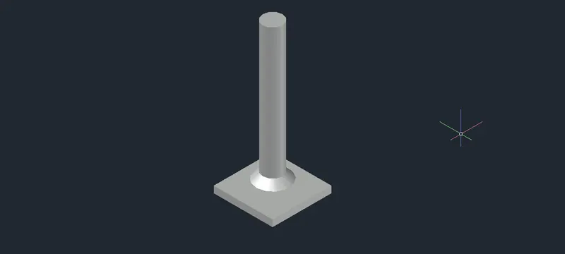
Question5. Create the 3d model of a wall as shown in Figure. Consider wall thickness as 9”.
AIM: To create the 3D model of a wall as shown in Figure. Consider wall thickness as 9”.
INTRODUCTION: AutoCAD allows the user to create the 3D objects in the software. In this question we will be learning about the isometric view of the elements in a detailed manner. The detailed procedure is given below step-by-step.
PROCEDURE:
- In order to create the 3D or isometric views in the AutoCAD software first we need to go to the AutoCAD software. Just open the AutoCAD software.
- Open the new file in the software.
- After opening to the new file set the units as the Architecture,change the units as feets and inches and the precision as 0'-0". And then press OK.
- Now set the limits as 10000',10000'.
- Now after setting the units and the limits,just change the workspace setting because we want to draw the isometric view in the workspace.
- So change the workspace setting as 3D workspace with drafting and the annotation.
- To change the workspace setting go to the right bottom of the AutoCAD software there is an option called setting from that there is an option called 3D modelling click on that option, then your space as 3D modelling have been created as shown in the below figure:
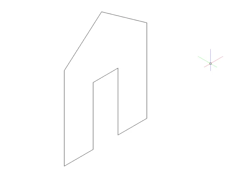
- So in order to create the 3D gable wall first we need to draw the frame of the wall.
- We can draw the wall by using the line command.
- Just type L in the command line and then press Enter.
- Draw a line of 3'-6" in the positive x-direction.
- Now draw another line of 8' in the z-direction.
- A line of 3' in the x-direction.
- Now a line of 7' in the downward z-direction.
- Again create a line of 3'6" in the x-direction.
- Now draw a line of 7' in the upward z-direction.
- Like wise draw the other lines to complete the geometry of the frame just as shown in the below figure:
- Now after creating the wall structure use the region command, to make different elements into one element.
- Just type REG in the command line and then press Enter.
- Now select the objects and then press Enter.
- Now the whole wall is one element.
- After creating the region,use the Extrution command.
- To use the extrution command go to the Home tab there is an option called Extrude just click on that and select the object which we want to extrude.
- Now give the wall a depth of 9".
- Now the wall has been extruded using the extrude command just as shown in the below figure:
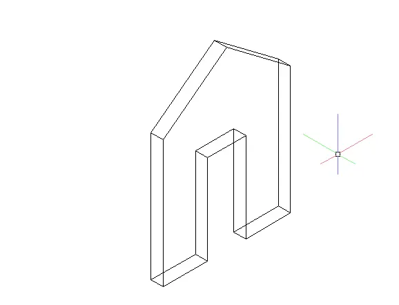
- Now after that use the hide command to hide the extra wireframe.
- Just type HI in the command line and then press Enter.
- All the extra lines and we can say the extra wireframe has been hidden now just as shown in the below figure:
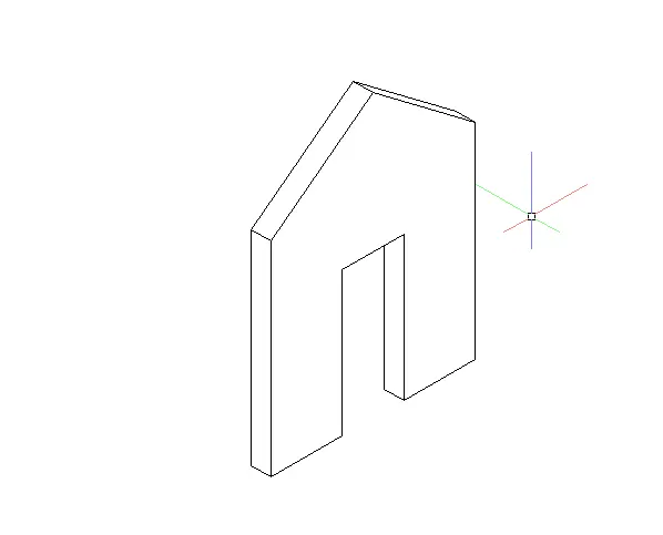
- Now change the view to the Shaded/Realistic view to see the Solid 3D model as shown in the below figure:
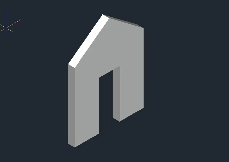
FINAL RESULT:
(a) 3D Furniture element:
(b) 3d Model of an Isolated footing:
(c) 3D view of the AASTHO Type Girder:
(d) 3d Model of a drop column with panel:
(e) 3d model of a wall: