Creating various 3D Models like Furniture, Footing, Girder, Column drop with panel and Gable Wall in AutoCad
AIM :
To create 3D model and view of
- furniture element
- isolated footing
- AASTHO type grider
- drop column with panel
- a wall
COMMANDS USED :
- Extrude
- offset
- UCS
- Box
- Union
- Subtract
- Move
- 3D orbit
- Loft
- Sweep
- Cone
- Region
- Boundary
PROCEDURE :
Open the auto cad . click on work space switching and change into 3d modelling and click on the home button.Near the view cube , Set the Limits and Zoom All
1. Drawing 3D Furnitrure Element :
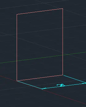
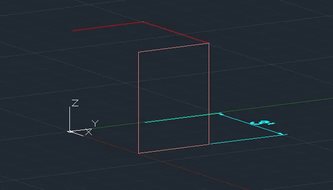
- Assingning all layers as follows,
- use face3d command, select four corners of the face and press enter
- change the view style control to shaded and check for face.
- change the view style , control to hidden and check for face.
- follow the same procedure for all faces of the model.
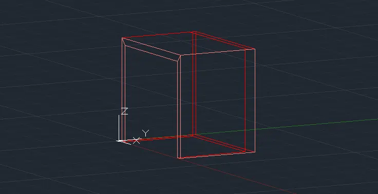
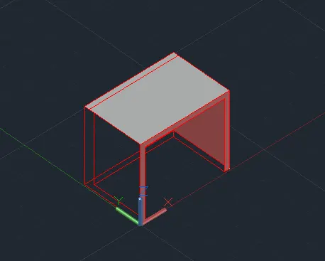
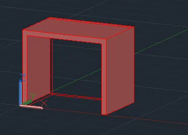
- change the view style control to shaded and check for face.
RESULT :
The 3D model of the furniture equipment is drawn, in the above steps , the results consists of model assigned with the layer , the model is draw as shown in above, 3D FACE command is used to darw all surfaces, (All dimensions are in feet and inches).
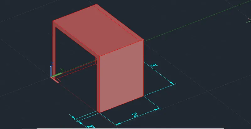
2. Create the 3d Model of an Isolated footing as shown in Figure.
AIM :
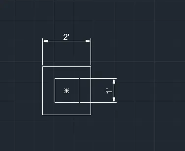
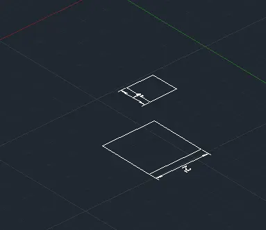
To Draw the 3D wire frame model of an isolated footing as shown in figure.
INTRODUCTION :
An isolated footing is one of the most used types of foundation to support single-columns when they are arranged at a long distance. An isolated footing must be designed to avoid exceeding its bearing capacity and provide safety against overturning or sliding while preventing the ground from settling
PROCEDURE :
- Open AUTO CAD, units are set to engineering and inches,
- limits are also set,
- create rectangle 2'*2' on top view, and 1'*1' on top view.
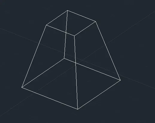
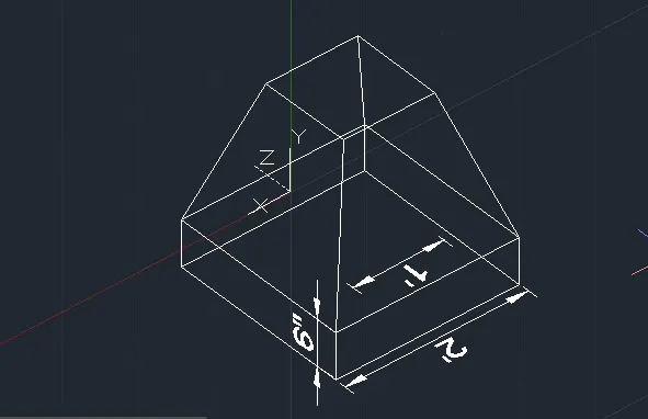
FINAL RESULT :
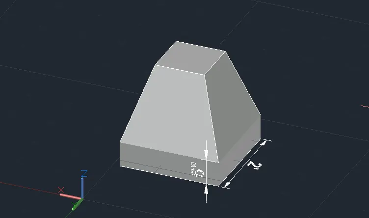
3. Create the 3D view of the AASTHO Type Girder.
AIM :
To create a 3D model of AASTHO Type grider using AUTO CAD 3D,
PROCEDURE :
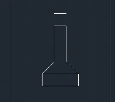
- Click on front view use ucs command, make x and y axis in the front view plane.
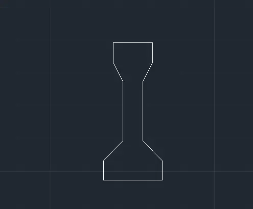
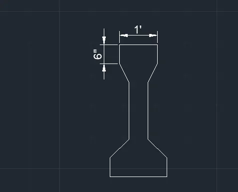
- then by line command , draw I section with the given dimension , draw a line 1' top width of the grider.
- with a line draw a 6" downwards , with snap on draw a line from the center of 1' and offset 3" on both sides such that width of web becomes 6"
- give the taper distance join the web and the flange mirror the same on the other side.
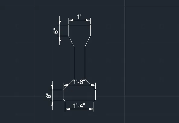
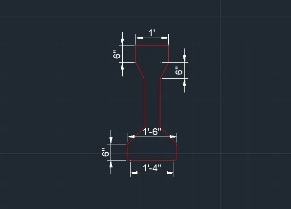
- offset 1'6" end of the taperinng on the flange portion,
- extend the web to the offset line , again offset 6"from thr offset line and taper the sides.
- offset 6" downwards from the bottom horizontal line to define the height, To draw the tapper @bottom 1'4" from the centre draw a line and offset 4"on both sides,
- extend 6" and offset the lines and trim the rest of the lines
- with 3d orbit turn the view draw the line of 10' in z direction , click on sweep from the home tool bar and select the section and , then the path through with the section to be swept,
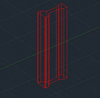
FINAL RESULT :
2D WIREFRAME MODEL:
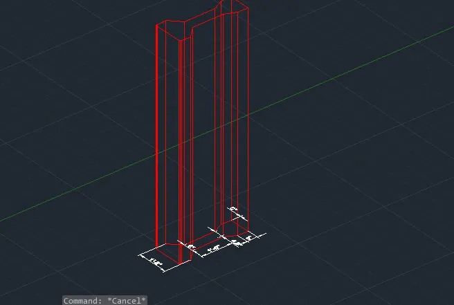
HIDDEN MODEL :
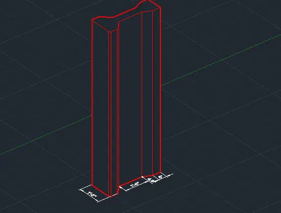
SHADED MODEL :
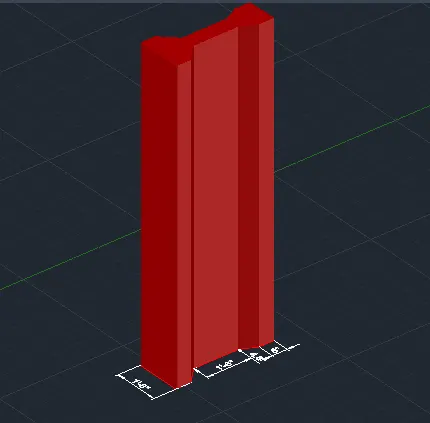
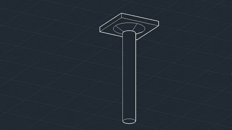
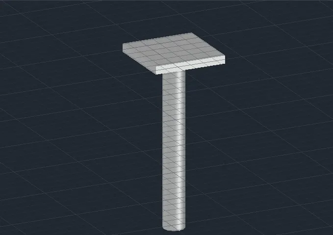
4. Create a 3d Model of a drop column with panel as shown in section and isometric view.
AIM :
To draw the 3d wireframe model of an drop column as shown in the figure.
INTRODUCTION :
irst, you define the table name from which you wish to remove or delete the column. Second, you write the column name you want to delete in the DROP clause. A user can also drop multiple columns simultaneously from a table. You can do this by listing out the column names that you want to drop, separated by a comma
- Direct design method
- Equivalent frame method
PROCEDURE :
- Open AUTOCAD
- set the units to Engineering > inches,
- set the limits also,
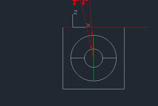
- Creating column top view,
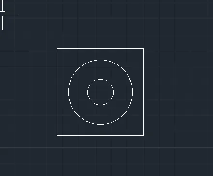
- draw a rectangle 4.5'*4.5'
- turn on geometric center, snap the object,
- draw a circle of dia 3'6" @the geometric centre of the square,
- draw another circle of dia 1'6" @the geometric centre of the square,
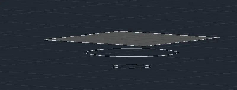
- using move command, moveall the components drawn in 2d @ a distance of 11'6"
- using move command move the both circles downwards @ a distance of -6"
- inner circle @ -1'
- create a region using region command inside the i section
- change the view style control to shaded
- go to view cube click on home
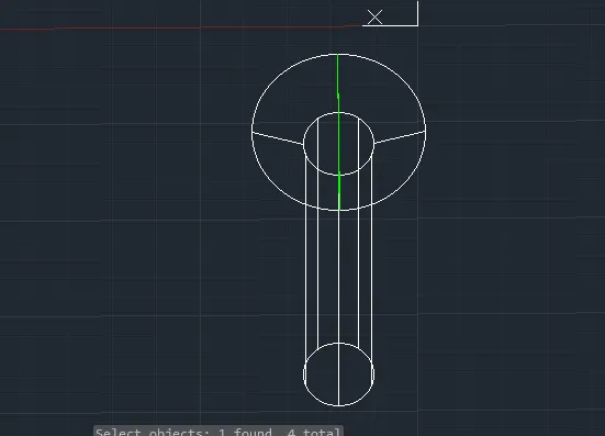
- using extrude command, top rectangle down upto -6"
- middle circle down upto -1'
- lower circle down upto -10'
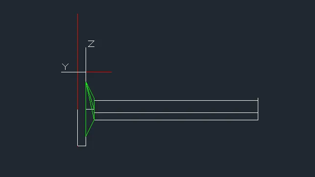
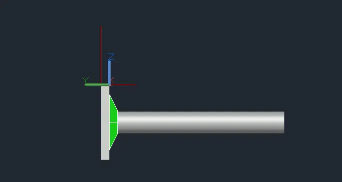
FINAL RESULT :
2D WIREFRAME :
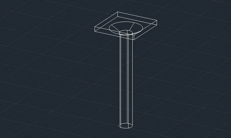
SHADED FRAME :
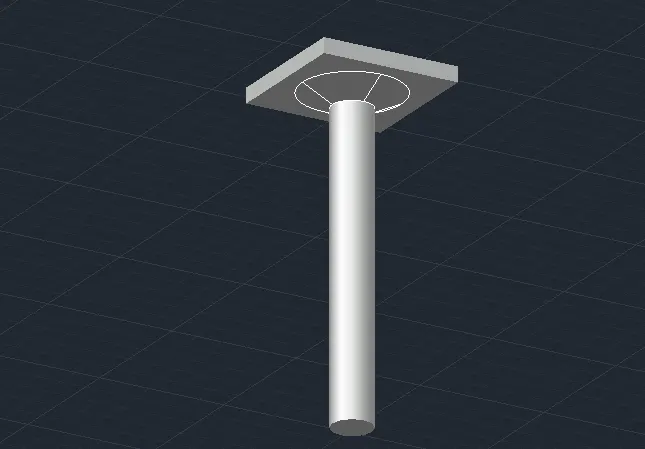
HIDDEN FRAME:
REALISTIC FRAME :
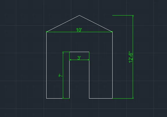
5. Create the 3d model of a wall as shown in Figure. Consider wall thickness as 9”.
AIM :
To draw a 3D model of a wall.
PROCEDURE :
STep 1
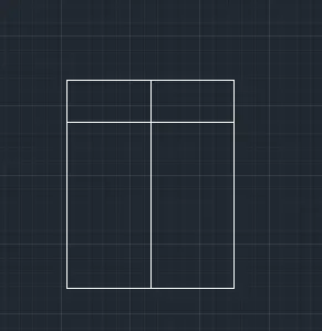
- draw a rectangle 10'*9" , create a line in the centre and offset 1.5" on both sides as 3" is the width of the door opening,
step 2:
- use the command BO for the boundary and create the region i.,e both the region on both sides door opening,
step 3:
- Extrude the region to a height oh 12'6" total height,
step 4:
- create a rectangle in the place of the door in the top view, move the rectangle in z axis @ a height of 7' from the bottom.
step 5:
- go to front view . draw a line from centre of moved line of the door , draw the slanting height of from the centre line intersecting,
step 6:
- Mirror the line to the other side, draw the horizontal, line to join.
step 7:
- trim the excess line and centre line and join the triangle with the join command, create a region with triangle created.
step 8:
- select the extruded rectangle with the help of grip bring it down to the level of the triangle base on the both sided. extrude the rectangle of the door to a height equal to base of triangle.
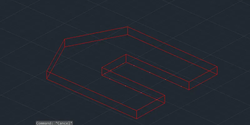
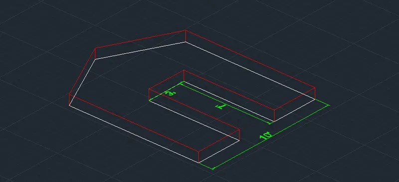
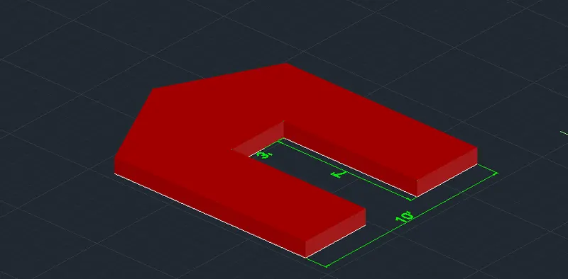
FINAL RESULT :
3D Model of wall is drawn :
realistic,
hidden,
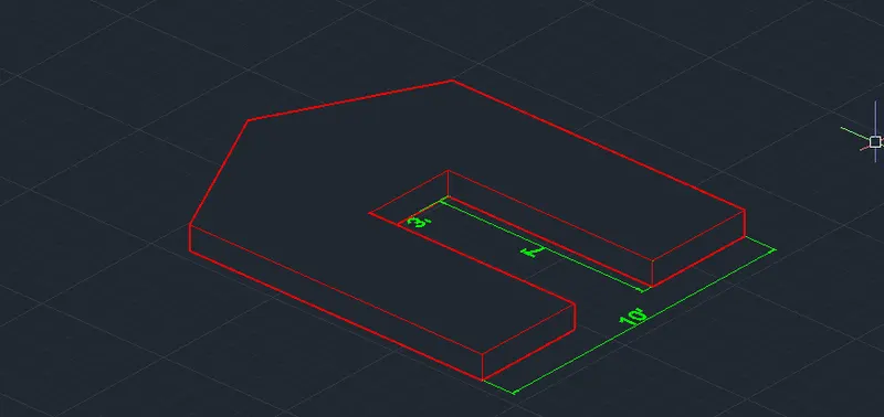
2D wire frame ,
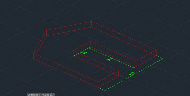
shaded of gray,
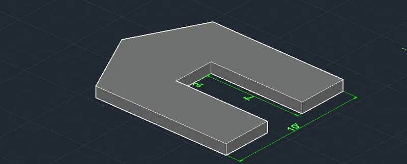
RESULT :
- 3D Model of furniture element is created ,
- 3D Model pf isolated footing is created,
- 3D Model of AASTHO type girder is created,
- 3D Model of drop column with panel is created,
- 3D Model of wall is created,