Creating Levels, Grids, Layout and model elements for a residential unit using REVIT
Q1.
What is BIM? Summarize the features of BIM and benefits of using BIM over 2D CAD tools.
Answer: BIM (Building information modelling) is a process of modeming based on the concept of compiling strategies and solution (Coordination and computation) at various stages of designing such as:
- Conceptual design
- Detail architectural and structure designs
- Analysis of the above to improve building performance
- Documentation of various parameters of project in a coordinated way
- Keeping a log of necessary construction logistics
Thus it provides a 360 degree understanding of the project.
Benefits of using BIM over 2D CAD tools:
- BIM ease outs real-time changes in a coordinated fashion for all disciplines at once which 2d cad tools don’t.
- Due to BIM, analysis of various parameters related to building design is possible to improve building performance, which 2d cad tools cant perform.
- Resource optimization can be achieved through sustainability evaluation and correction strategies through BIM.
- Parametric design is a major advantage to compute complex forms which are very difficult in 2d cad tools to achieve.
-----------------------------------------------------------------------------------------------------------
Q2.
Understand the concept of Categories, Families, Elements, and Instances in Revit. Go to Insert Tab, choose a category. Pick a family and element. Understand the instances and insert it to Revit model
Answer: The understanding of the following terminologies can be devoted through defining –
- Categories – it can be defined as the prime property of constituting elements shearing similar properties. The pre-defined properties in revit are walls, doors, windows, roofs, floors etc.
- Families – it is a subset of categories of elements like doors where you have a verity of doors based of their physical features. Eg. Singe leaf door or double leaf door.
- Elements – elements are the constituting modelling elements like walls, doors, windows, roofs, floors etc.
- Instances- it’s the lowest of the categories. When we place an object in to a model, it’s an instance of a type. These are very specific elements like 2100mm x 900mm door or 2100mm x 750mm door within the family of single leaf door.
Exercise: Pick a family and element. Understand the instances and insert it to Revit model
Step 1.
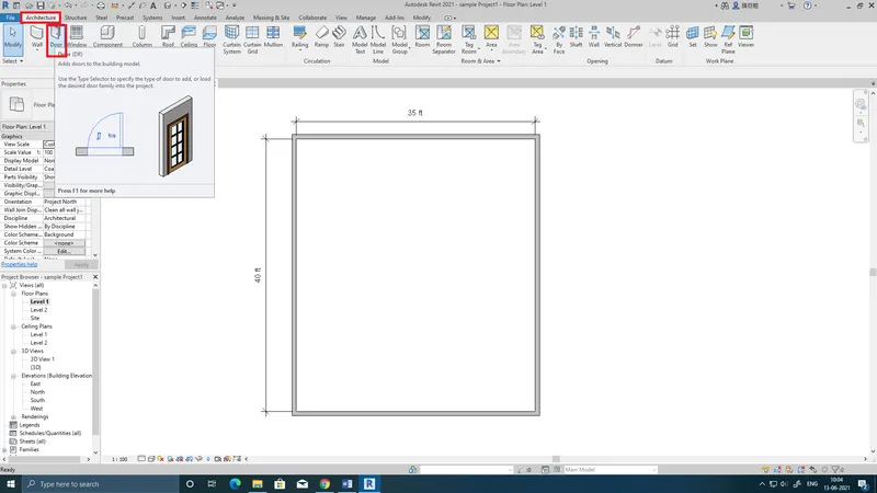
In architecture tab, select a family.
Step 2.
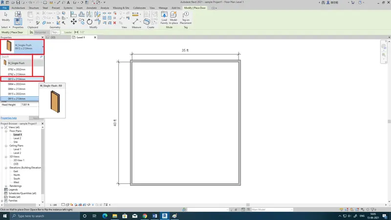
Under a family, select a instance and insert it as per given requirement.
Result:
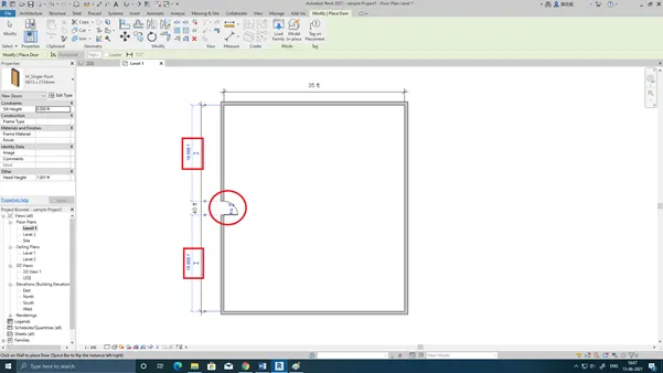
Instance is deployed at given location.
------------------------------------------------------------------------------------------------------------
Q3.
Setting up a Project – Open a project file with architectural template. Save the file with appropriate name. Set up the project units to Imperial / Metric based on your convenience of modelling. Complete the project information under Manage tab. Set up the maximum backups for project file to 3.
Procedure in detail:
Step 1:
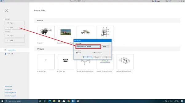
Start the application and press the new tab to open the new project window.
Step 2:
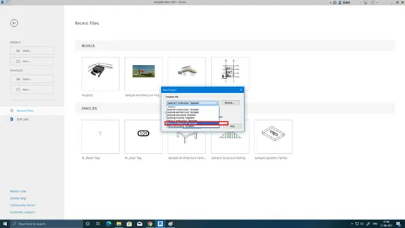
Scroll through the templates available and select the desirable template.
Step 3:
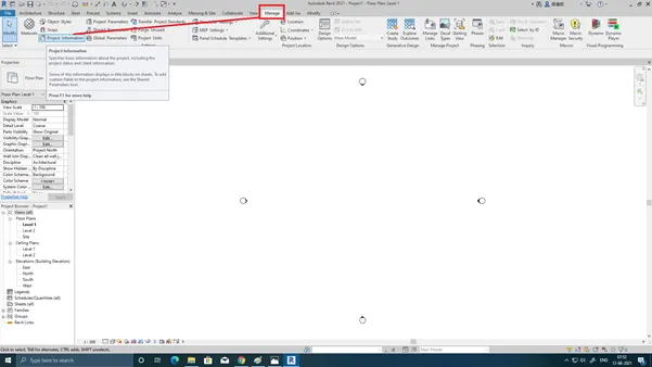
Go to manage panel button and click on project information tab.
Step 4.
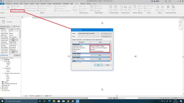
Under the project information window, fill-up all the desirable details such as identity data and other.
Step 5:
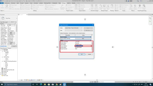
Click the project address extension.
Step 6:
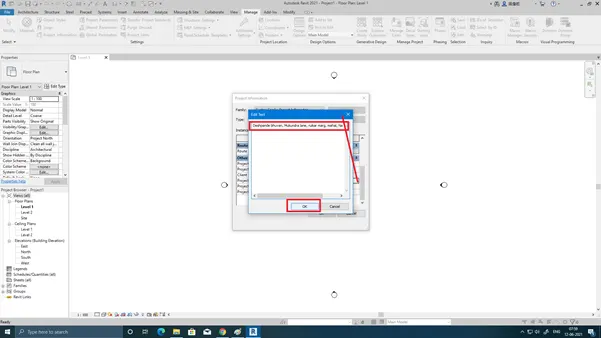
Enter the project address and click ok.
Step 7:
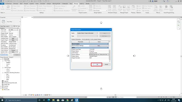
Click ok to finalize the information.
Step 8:
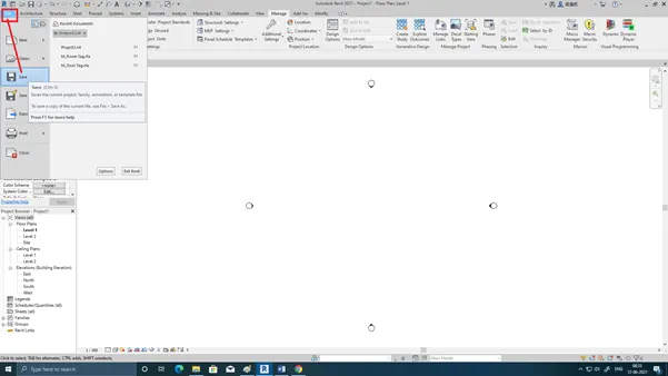
After opening the user interface, go to file menu and click the save tab.
Step 9
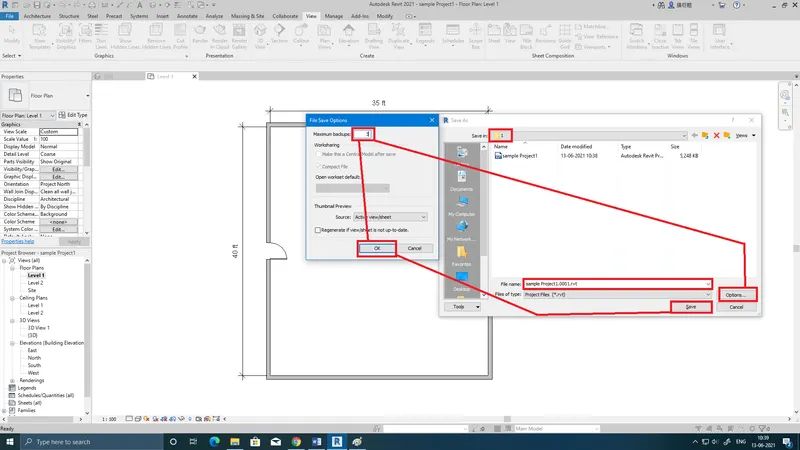
Before saving, go to options and set maximum backup to 3 click ok and then save the file.
------------------------------------------------------------------------------------------------------------------
Q4.
Aim: Understand the concept of Levels and Grids. Follow the naming and conventions. Create the following Levels: (Convert to metric equivalents if metric is your units)
Ground Floor @ 0’
First Floor @ 10’
Second Floor @ 20’
Roof @ 30’
Grids Transverse Grids A, B,C,D, E @ 10’ spacing
Longitudinal Grids from 1 to 10 @ 20’ spacing
ANSWER:
STEP 1.
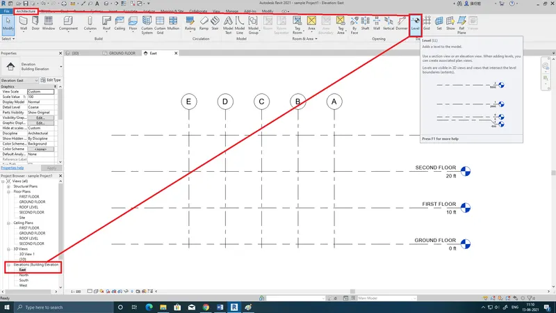
Under architecture tab, go to levels and engage. Select any elevation to view pre-set base levels.
STEP 2.
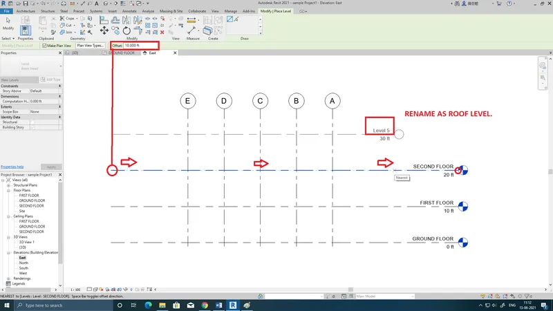
Rename base levels. Set desired offsets and draw over reference levels to set new levels. Rename new levels as desired.
Step 3.
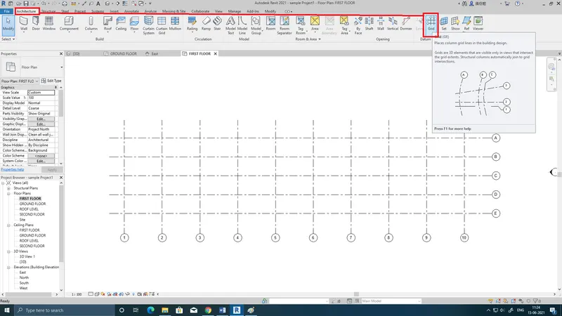
In order to setup the grid lines, go to architecture tab and engage grid.
STEP 4.
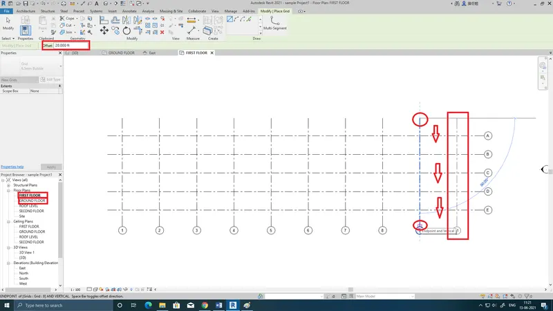
Similar to setting levels, determine offset distance from reference line and then rename as per standards.
Result :
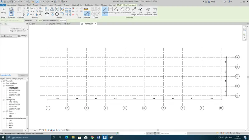
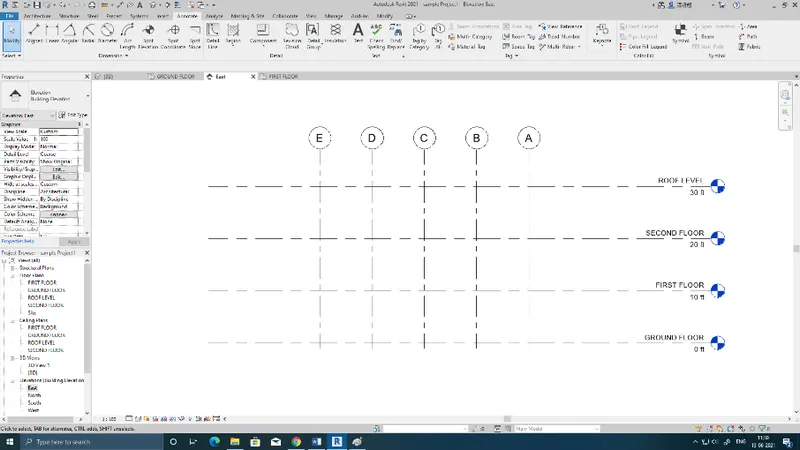
Levels set as :
Ground Floor @ 0’
First Floor @ 10’
Second Floor @ 20’
Roof @ 30’
Grids set as:
Transverse Grids A, B,C,D, E @ 10’ spacing
Longitudinal Grids from 1 to 10 @ 20’ spacing
------------------------------------------------------------------------------------------------------------------
Q5.
Aim: Make a 3D modelling of residential unit – From looking at your house / or a place you aspire. Create a conceptual layout of the residential unit. You can measure using a tape or
you can access your residential plan to create a similar layout.
Answer:
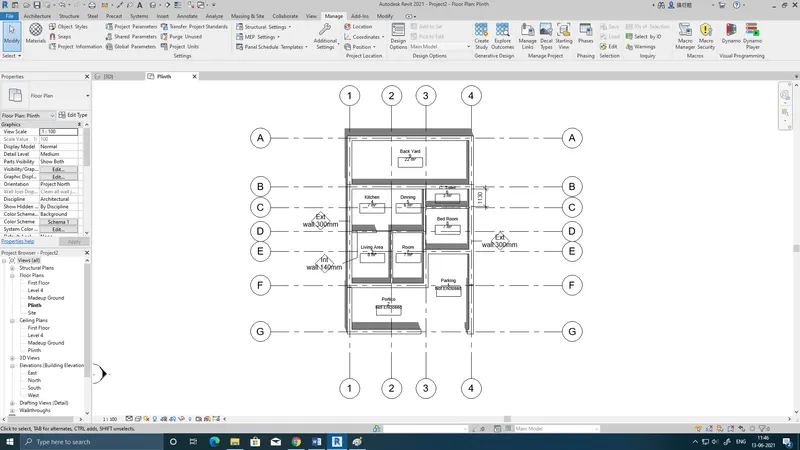
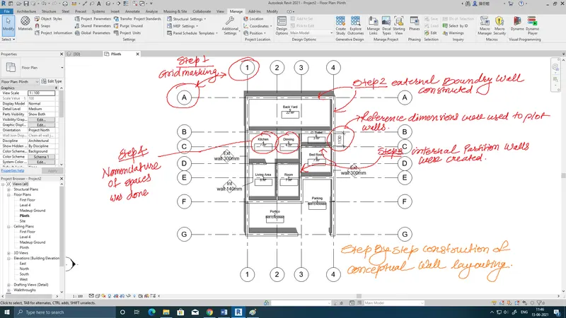
Step wise lay outing:
Step 1
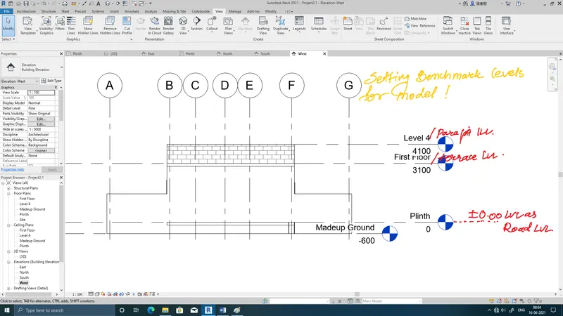
step 2:
Result ;
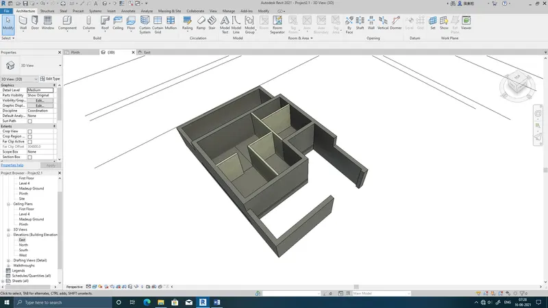
A conceptual layout of 2BHK residence has been created using generic 300m external wall and generic 140mm wall. As a result of this a 3d model has also been generated as shown.
-----------------------------------------------------------------------------------------------------------------
Q6.
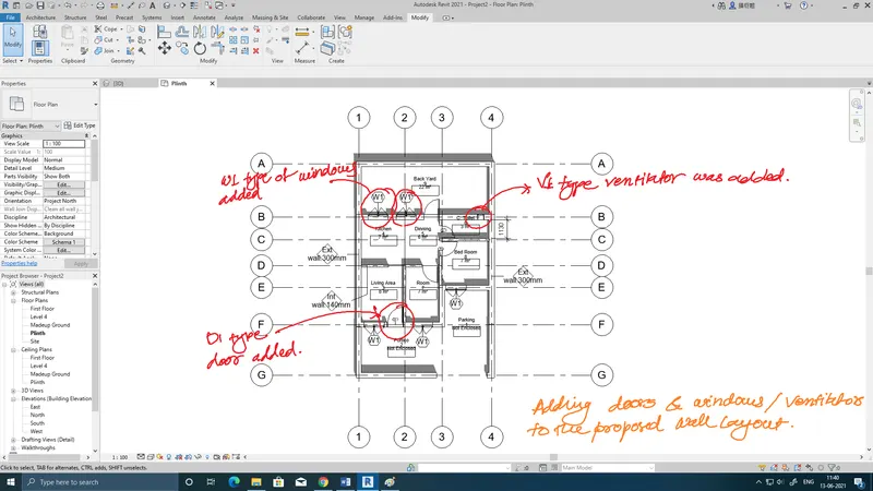
Aim: In the layout created draft the level of details you are planning to include – Dimensions of room, components you plan to add in the residential unit.
Answer:
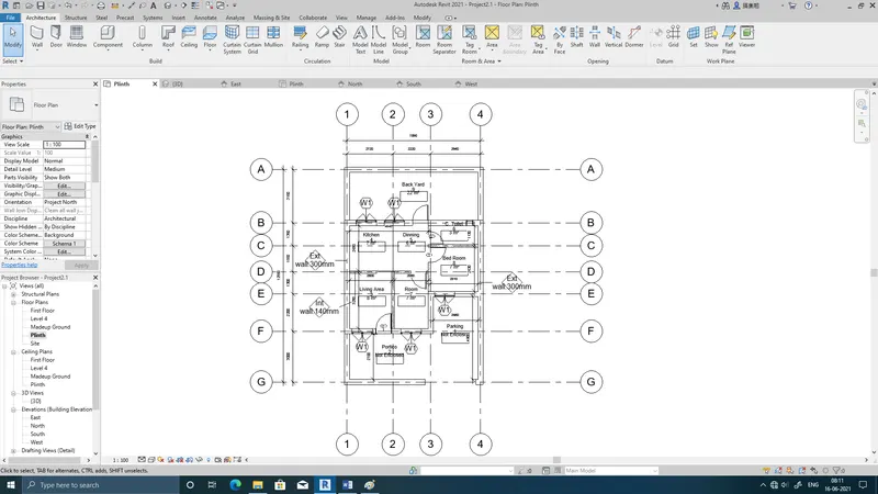
Step by step modelling_
Using the annotation tabs for linear and align dimension tool was used to provide external and internal dimensions.
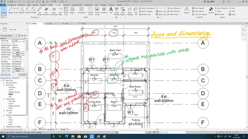
step 2:
Result : 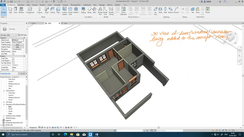
----------------------------------------------------------------------------------------------------------
Q7.
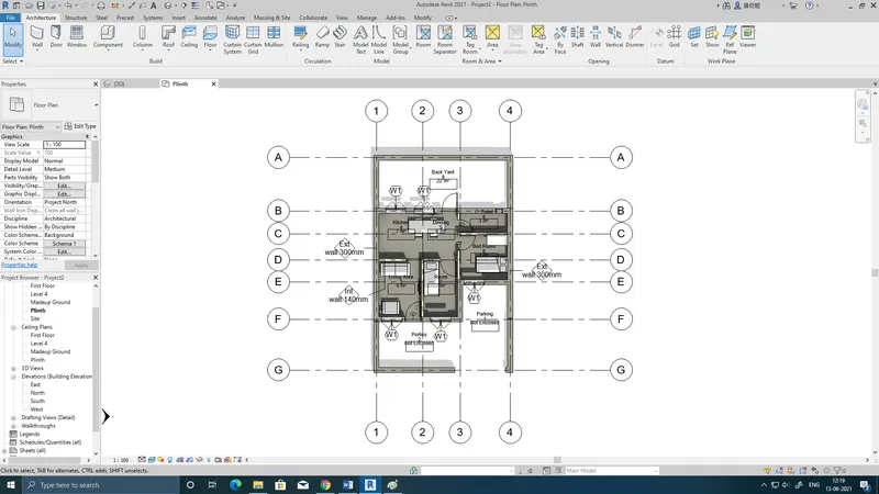
Aim: Identify the residential model elements such as Door, Windows, Tables, Chair, Couch, Bed, Lamps from the library and insert them to the model . Save the project for use
for Assignment 3
Answer:
Step by step modelling:
Step 1: from architecture tab deploy buiding elements like doors and other openings.
Step 2:
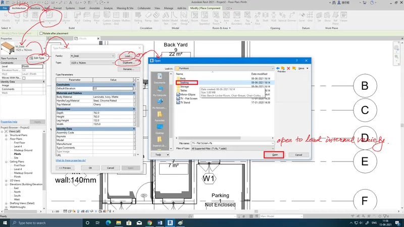
Step 3:
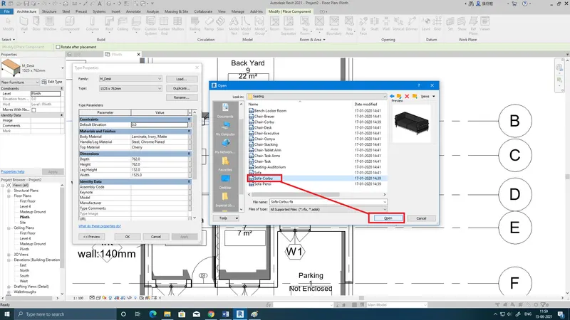
As shown in above diagrams, deploy furniture as per requirement.
Result :
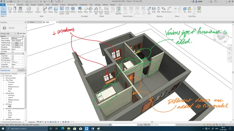
These steps can add elements such as Door, Windows, Tables, Chair, Couch, Bed, Lamps from the library.
------------------------------------------------------------------------------------------------------------------