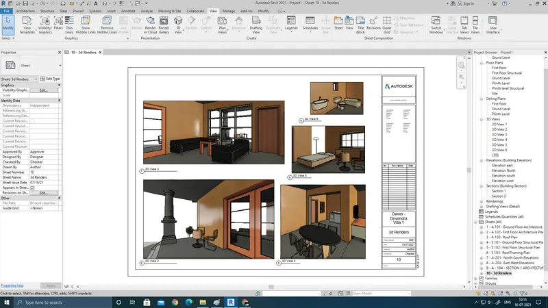
3D Creation of Celing, Roof, Architectural plan, Structural plan, Sectional view, Elevation view and Camera specific view for a house plan using REVIT
1) Based on the project saved from Week 3, proceed from the First Floor Level. Model a Ceiling from the architecture tab above the walls at the first-floor level
Answer:
Introduction: A false ceiling has to be created at the first-floor level, above the walls.
Stepwise Procedure:
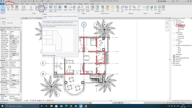
Step 1: engage first-floor level from project browzer window. Then under the architectural tab, engage the ceiling tab.
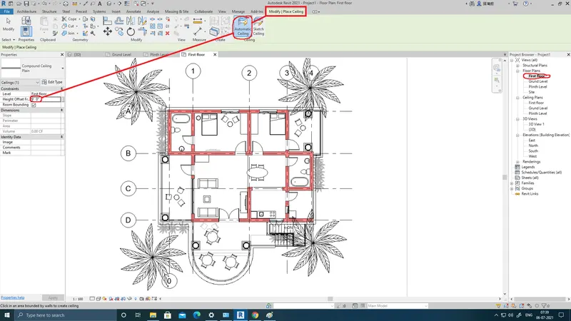
Step 2: After modify tab is opened, select the appropriate type of ceiling you want. Also, enter the specific height of the ceiling you want from the floor level.
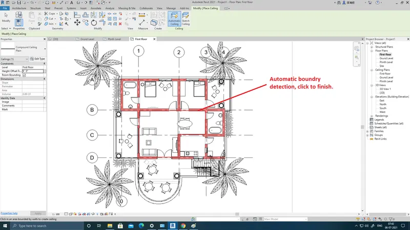
Step 3: As you hover the mouse over an enclosed space, the boundary of the room is highlighted automatically. Click to finish creating the ceiling.
Result
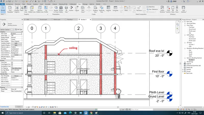
a ceiling has been created on the first floor, above the walls at the first-floor level. @9'
-------------------------------------------------------------------------------------------------------------------------------------------
2) Model a roof above the ceiling by selecting the footprints of the ceiling. Using the adjustment toolbars appearing on-screen adjust the roof slope to 10 degrees.
Answer:
Introduction: the aim is to construct a roof above the first floor.
Stepwise Procedure:
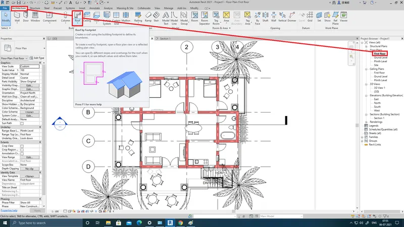
step 1: Go to first-floor level, under the architectural tab, engage roof.
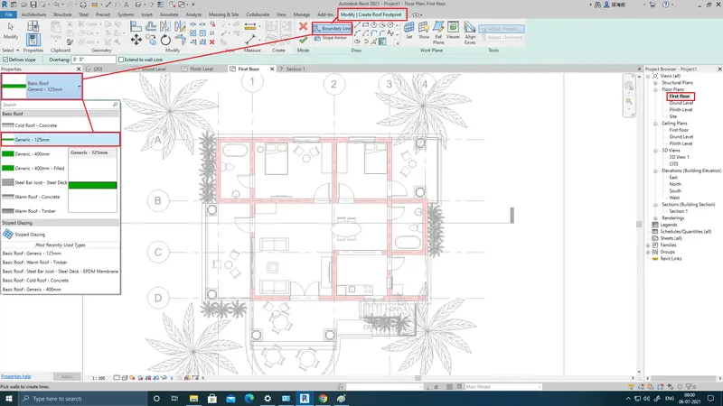
step 2: As the modify tab opens, select the boundry line option or pick boundry as you want. select the type of roof you require and start drafting.
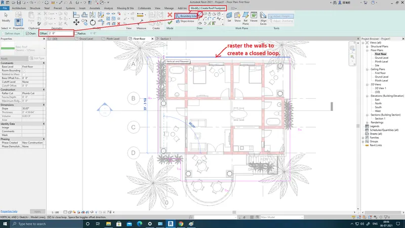
Step 3: raster the walls to create a closed-loop. You may give an offset if required.
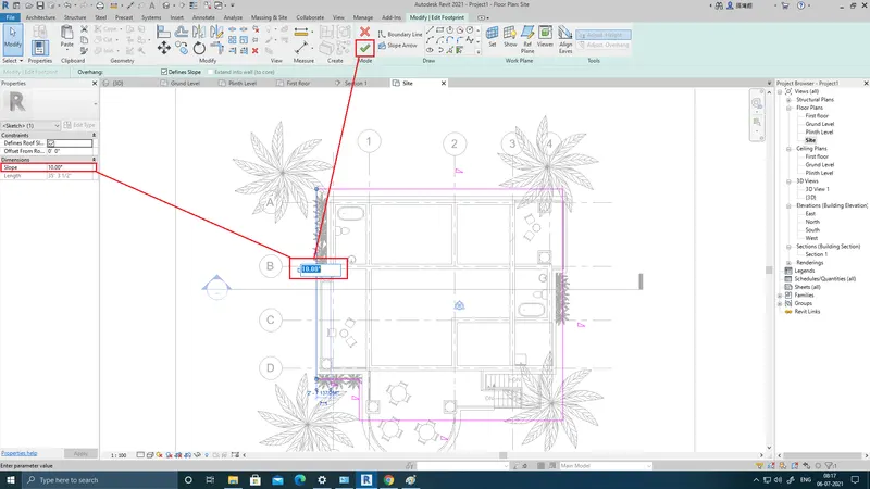
step 4: by selecting the roof edges, enter the desired pitch of the roof as angles. (10Degree)
Result:
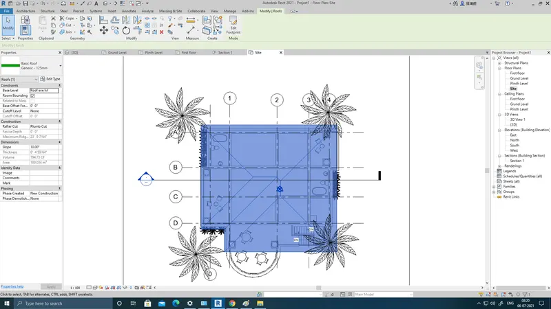
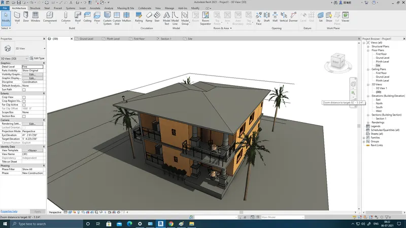
Thus the roof is created at the desired level with desired pitch. the ridges and valleys are created automatically.
----------------------------------------------------------------------------------------------------------------------------------------------
3) Using the file saved from weeks 2 to 4, create plan views for ground floor level and first-floor level including all the walls, floors, and components. Separate them to
architecture and structural plans
a. Architecture plan must have walls, floors, and all the components placed within the building
b. Structure plan must have details of only walls, floors, and columns
Answer:
Aim: To Create architectural and structural plans differently with some components visible.
Stepwise procedure:
Step1:
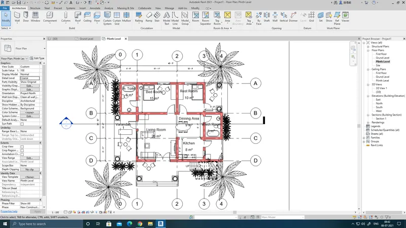
The architectural Plan containing walls, floors, and all the components placed within the building.
Step 2:
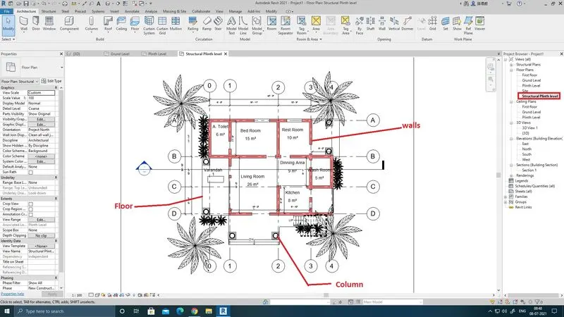
By creating a duplicate of a floor, hide the unwanted elements and keep the structural elements only.
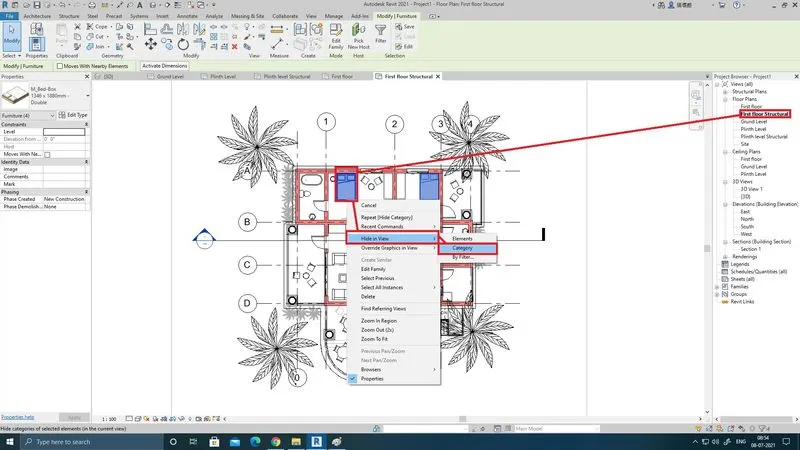
Hide the elements by category or by elements.
Result:
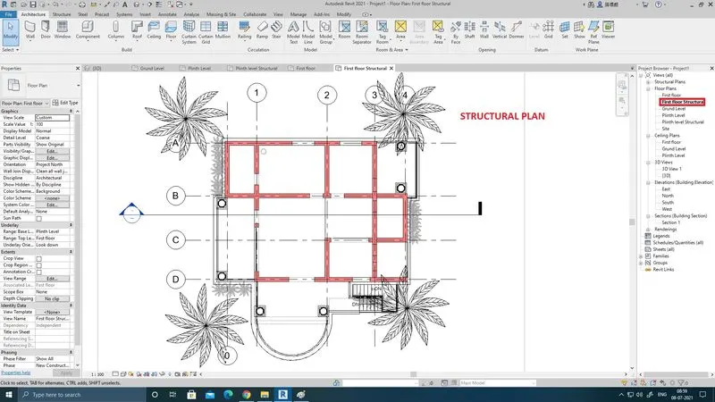
Thus, a Structure plan having details of only walls, floors, and columns have been created.
-----------------------------------------------------------------------------------------------------------------------------
4) Using annotate toolbar add dimensions to all the walls and floors concerning the longitudinal and transverse grids created in the project file
a. The architecture plan dimensions include details on where the components are placed within the buildings with relation to grids. Overall dimensions are sufficient for architecture plans
b. The Structure plan dimensions must include details on the position of all the walls and interior walls concerning grids. Locate all the framing components of the building concerning a fixed point using Structural plans
Answer:
The aim is to provide the necessary dimensions of various components and elements concerning grid lines.
Stepwise Procedure:
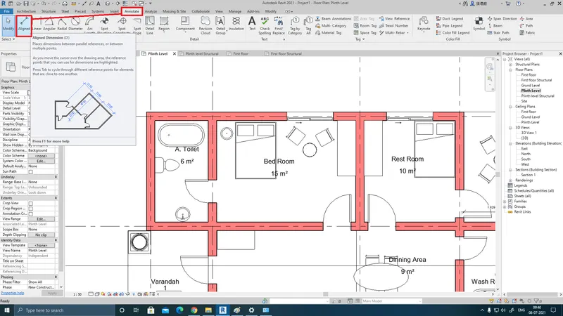
Step1: Go to Annotate tab and select an aligned dimension.
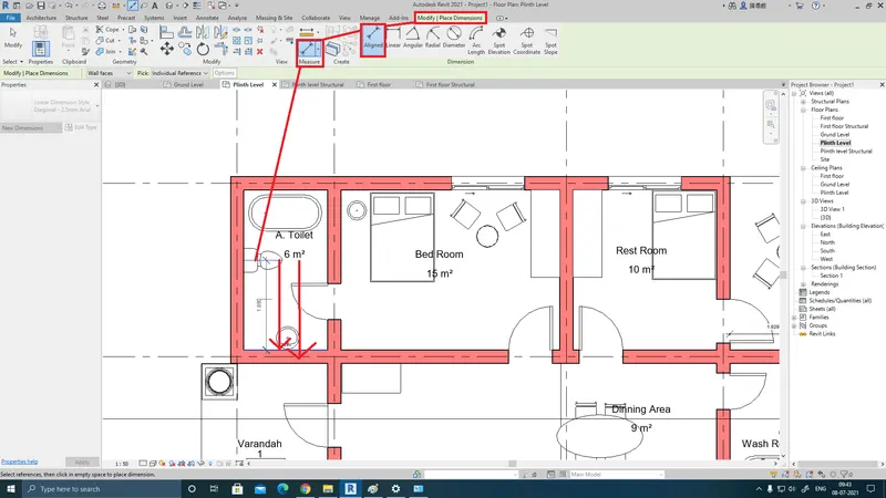
Step 2: Once the Modify tab is opened, hover over a component to select the reference start. click to engage and then go to the nearby grid line to end the dimension line.
Result :
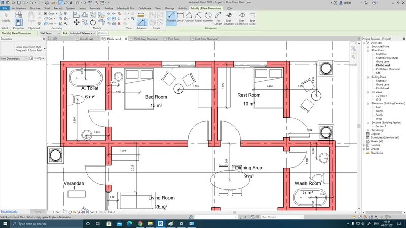
Thus, The architecture plan dimensions include details on where the components are placed within the buildings with relation to grids.
Similarly,
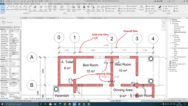
The Structure plan dimensions include details on the position of all the walls and interior walls and openings concerning grids.
------------------------------------------------------------------------------------------------------------------------------------------------------
Q5) Create a sheet template from the view tab and adjust the parameters on the sheet to add appropriate views.
Answer: Aim: the aim is to prepare a sheet well formated with project views.
Stepwise Procedure
Step 1:
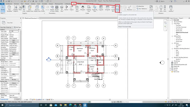
Under view, the tab goes to the sheet.
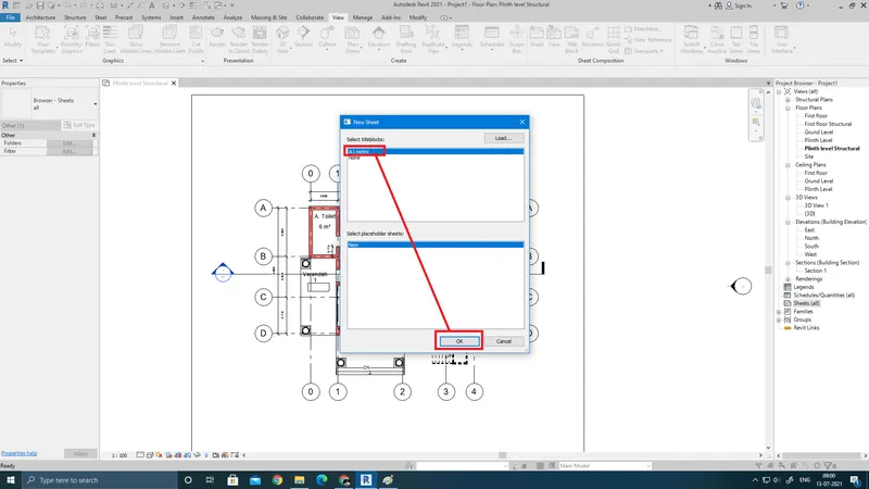
Step 2: Select the desired title block and click ok
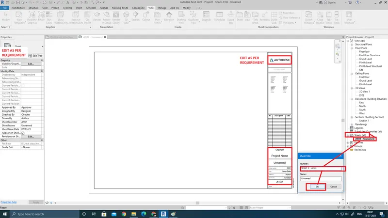
Step 3: Edit sheet title block as per your requirements.
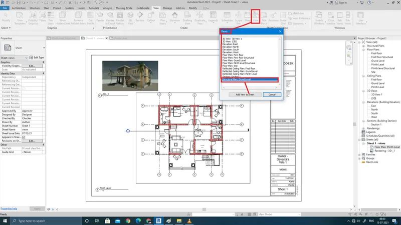
Step 4: Enter desired views or plans by clicking the views tab beside the sheets tab and click add views to the sheet. Scale them as per sheet layout.
Result :
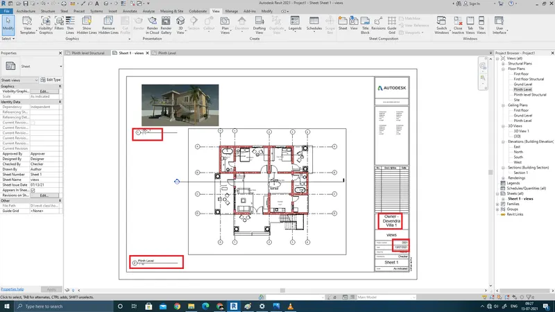
Thus, sheets with desired views or contents are created.
-----------------------------------------------------------------------------------------------------------------------------------------------
Q6) Using the elevation tab create the elevation views, looking at your building from East, North, South, and West
Answer:
Aim: Create the elevation views using the elevation tab for cardinal directions.
Stepwise procedure:
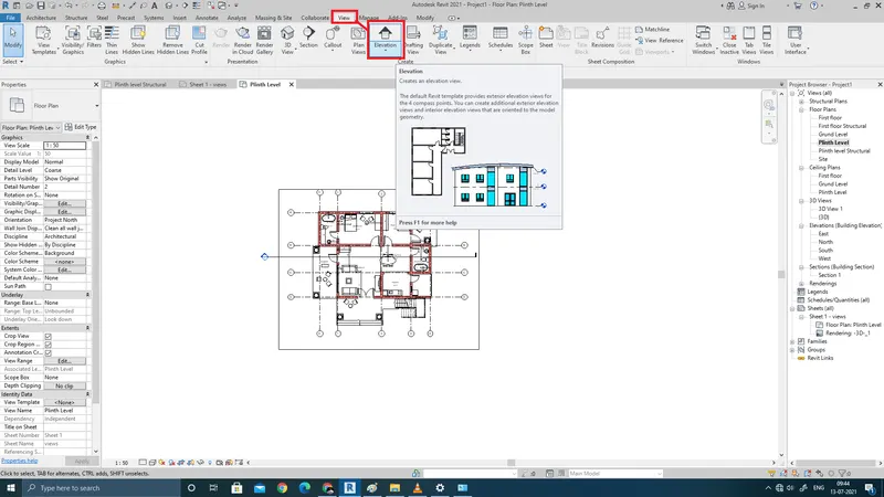
Step 1: go to the view tab and click the elevation tab to engage.
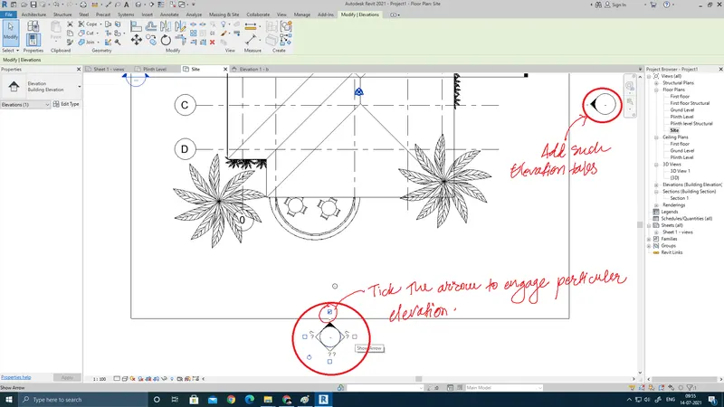
step 2: Click on sides to crate elevation annotations. after that, double click them to enable multiple directional views if required.
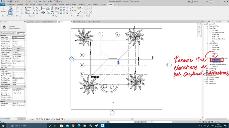
Step 3: As views are created, rename them as per building orientation. e.g. east elevation
Result :
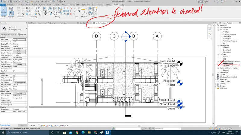
Thus, building elevations from East, North, South, and West directions are created.
---------------------------------------------------------------------------------------------------------------------------------
Q7) Produce section cut through each room either cutting across longitudinally or in a transverse direction.
Answer:
The aim is to create sections explaining the various spaces within the structure.
Stepwise procedure:
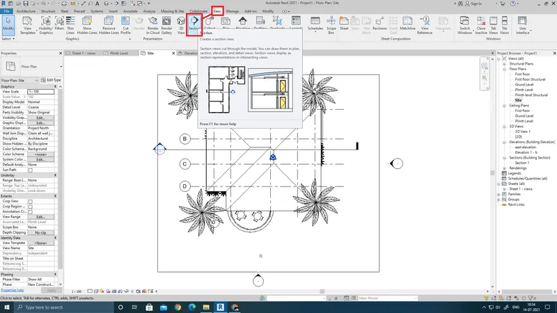
Step1: Go to the View tab and click sections to engage.
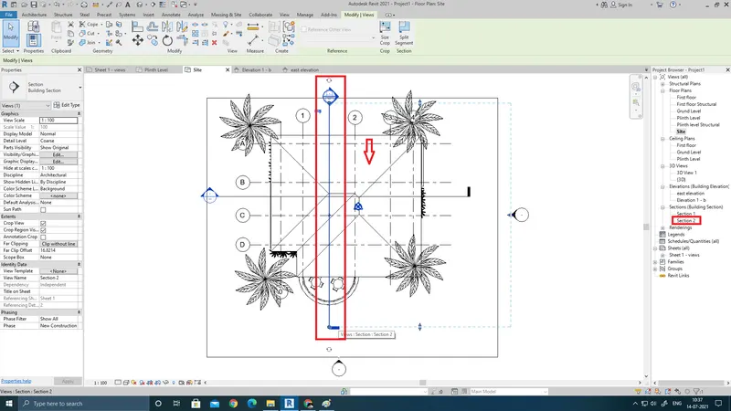
Step 2: Click and drag the section line through the building and orient the section in the desired directions.
Result:
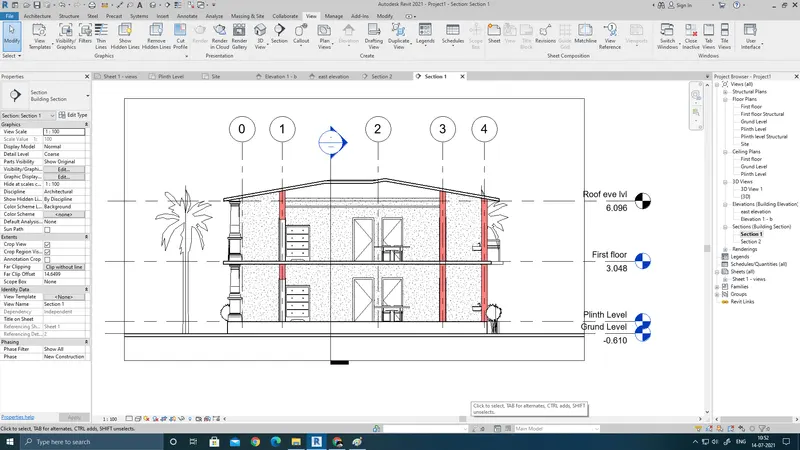
Section - 1. lateral
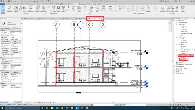
Section 2 : longitudional
Thus, sections are created cutting across longitudinally or in a transverse direction.
_____________________________________________________________________________________________
8) Classify the views, Plan Views, Section Views, and Elevation views to either Design or Documentation category using Properties browser
Answer: Not understood the question.
_______________________________________________________________________________________________________
9) Using the sheet template produced create multiple sheets as follows
a. A 101- Ground Floor Architecture Plan
b. A 102- First Floor Architecture Plan
c. A 103- Roof Plan
d. S 101- Ground Floor Structural Plan
e. S 102- First Floor Structural Plan
f. S 103- Roof Framing Plan
g. A-201- North-South Elevations
h. A-202- East-West Elevations
Add additional sheets based on the sections created in your Revit file
ANSWER: Aim : is to prepare multiple sheetsthrough templets as enlisted
Stepwise Procedure
Step 1:
Under view, the tab goes to the sheet.
Step 2: Select the desired title block and click ok
Step 3: Edit sheet title block as per your requirements.
Step 4: Enter desired views or plans by clicking the views tab beside the sheets tab and click add views to the sheet. Scale them as per sheet layout.
Result: Thus, by above procedure we can create the enlisted sheets with appropriate contents.
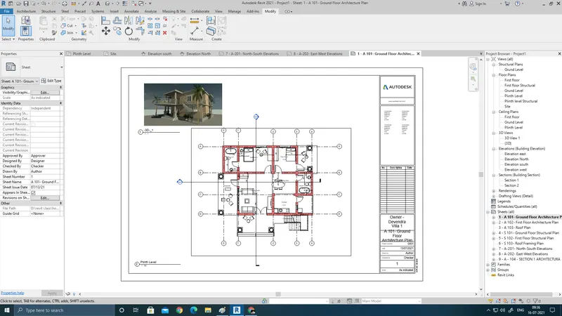
A 101- Ground Floor Architecture Plan
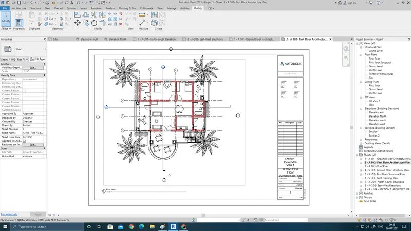
A 102- First Floor Architecture Plan
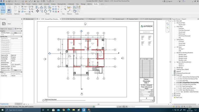
d. S 101- Ground Floor Structural Plan
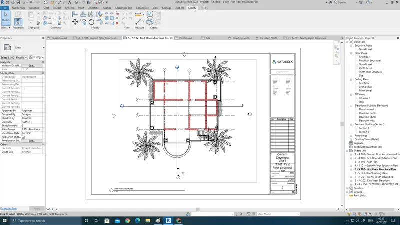
S 102- First Floor Structural Plan
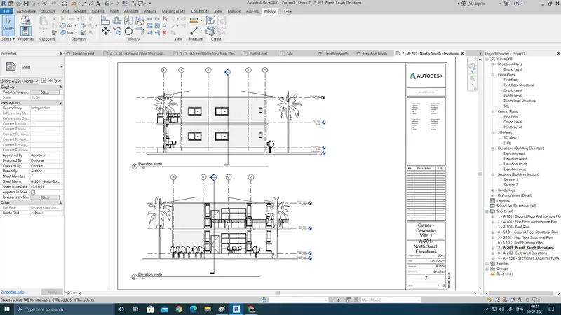
A-201- North-South Elevations
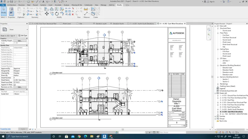
A-202- East-West Elevations
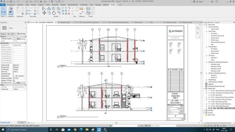
A - 104 - SECTION 1 ARCHITECTURAL
------------------------------------------------------------------------------------------------------------------------------------------------------
10) Create a camera-specific view or a 3D view in each room ( living, dining, bedroom). Based on the views create a new set of sheets starting A-501 (you can add as many sheets after, 502, 503.. n)to place the 3D view images. Produce the sheets as a part of project drafting.
Answer: AIM: The aim is to create documented sheet incorporating all the renders of internal spaces using specific camer.
Procidure: step 1:
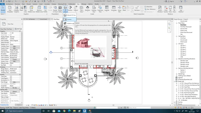
Go to specific floor plan and go to view tab. under 3d view option, click on camera option.
Step2:
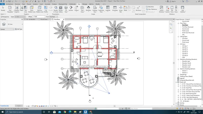
then click the view point and set the camera direction and far reach. Click to engage.
step 3:
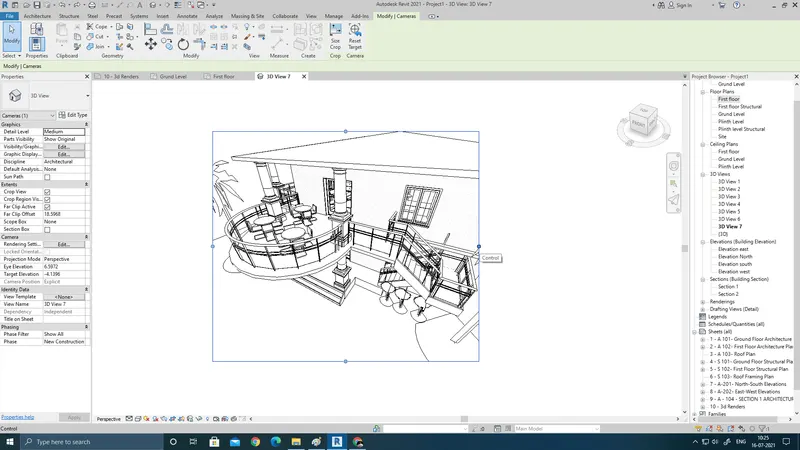
set the vision boundaries to cover appropriate content.
step 4:
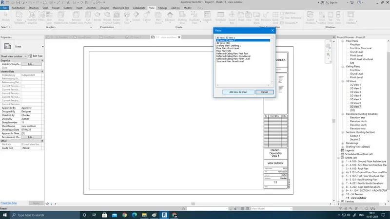
insert the view in to the sheet and scale the view to fit.
Result: Thus we can create a sheet including all created views.