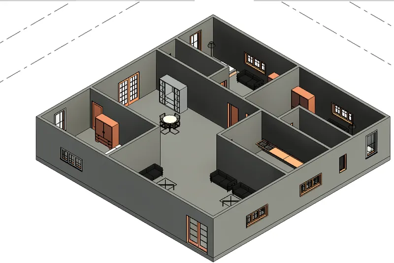
Creating Levels, Grids, Layout and model elements for a residential unit using REVIT
1.BIM:
- Building Information Modelling is a process for creating and managing information on a construction project across the project lifecycle.
- One of the key outputs of this process is the Building Information Model, the digital description of every aspect of the built asset.
- BIM is a process that architects use to design and construct modern buildings.
- The process encompasses several different design tools and methods with the end goal of making every phase of construction and design as efficient, safe, and cost-effective as possible.
The features of BIM:
- It enables the easy access of information
- It provides comprehensive view of entire project
- It gives real-time collaboration.
Benefits of using BIM over 2D CAD tools:
- 2D CAD allow us to work in 3 dimension which is length, breadth and depth where allow us to work in 5-dimension time and cost efficiency including length, breadth and depth.
- It gives instant updates ahead of time
- Resource tracking is fed in initial stag of design which enhance the flow and efficiency of the process during the construction.
2.Aim:
The concept of Categories, Families, Type, Instances in Revit.
Category:
- Categories control the organization, visibility, graphical representation and scheduling options of a particular set of families within the project.
- Examples of categories are doors, windows, columns, ducts, etc.
Family:
- Family in Revit is that it is a group of components used to build a model.
- For example, walls, windows, stairs, doors, bathrooms, fixtures, showers, etc., with a common set of properties, or parameters, and a related graphical representation.
Type and Instance:
- Each family is controlled by type and instance parameters within the project.
- Instance parameters affect individual instances only.
- Type parameters affect all instances of the same type in the entire project.
Procedure to insert it in the model:
Open Revit software
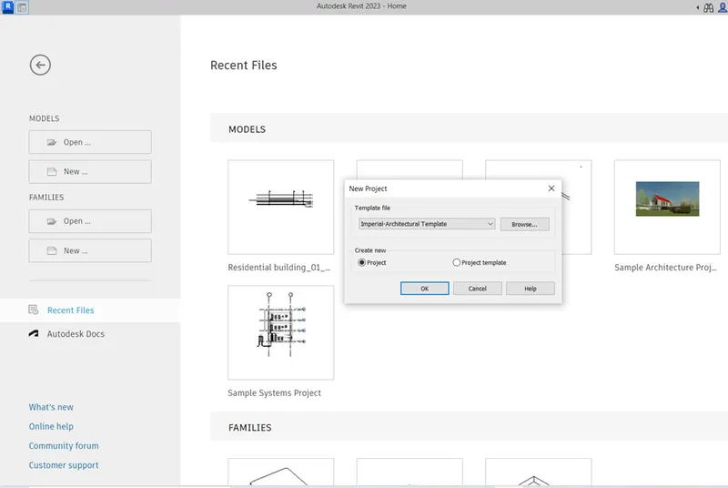
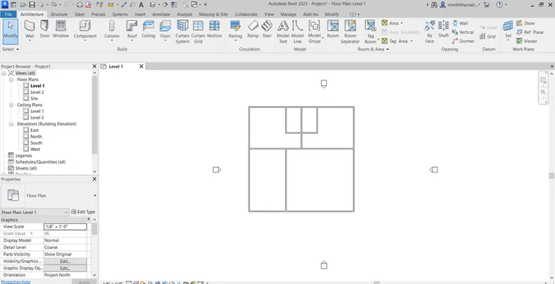
Create a plan using wall command from Architecture tab
Select Insert and load family

Select the category as Door
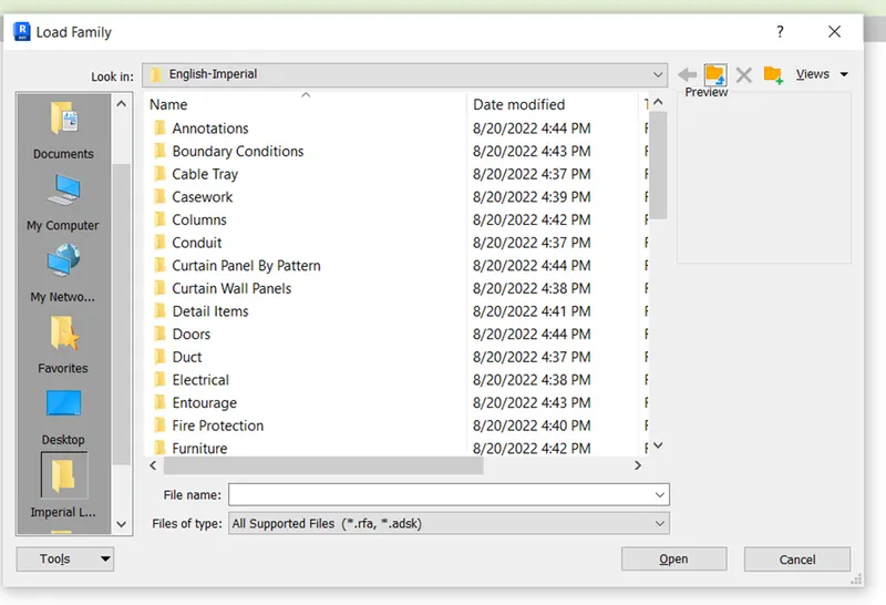
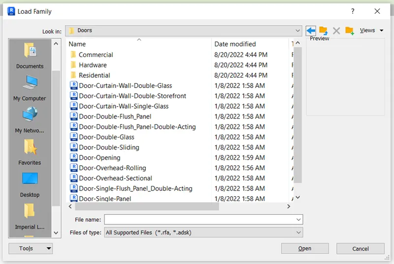
Select the family as residential
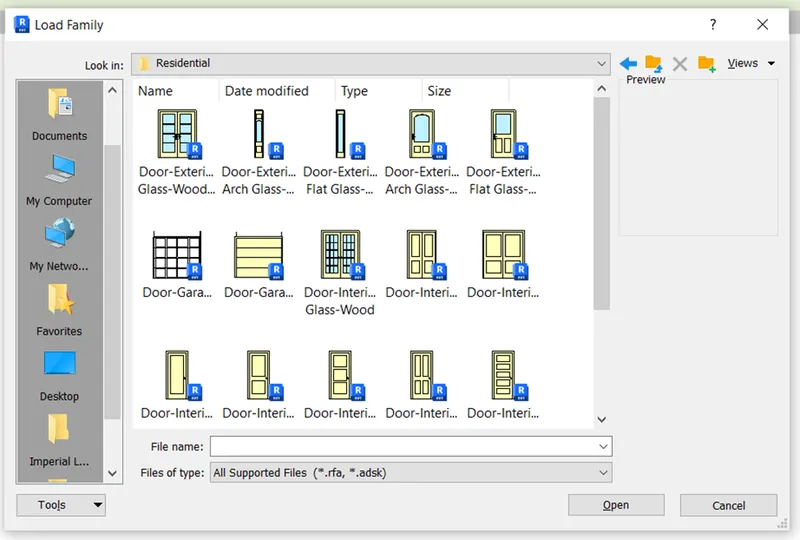
Select the type
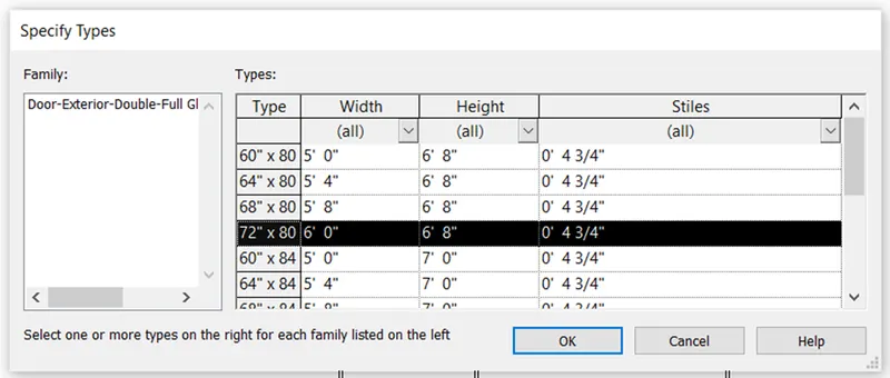
And place is it in the desired place
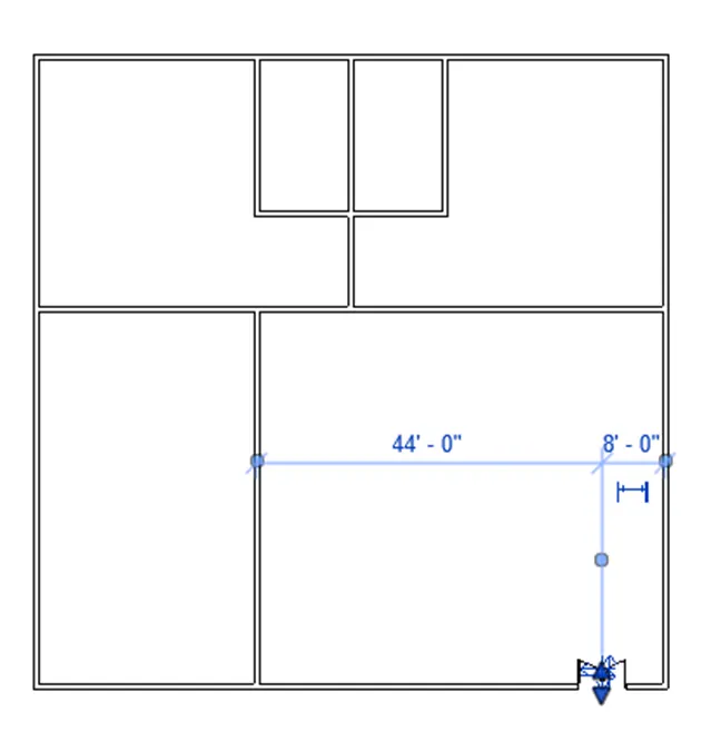
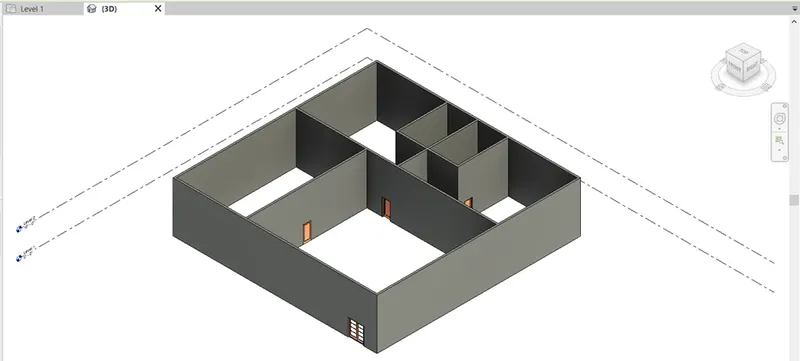
Result:
The result is obtained by the above steps
3.Aim:
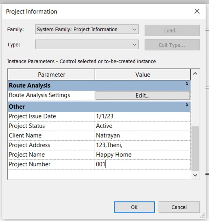
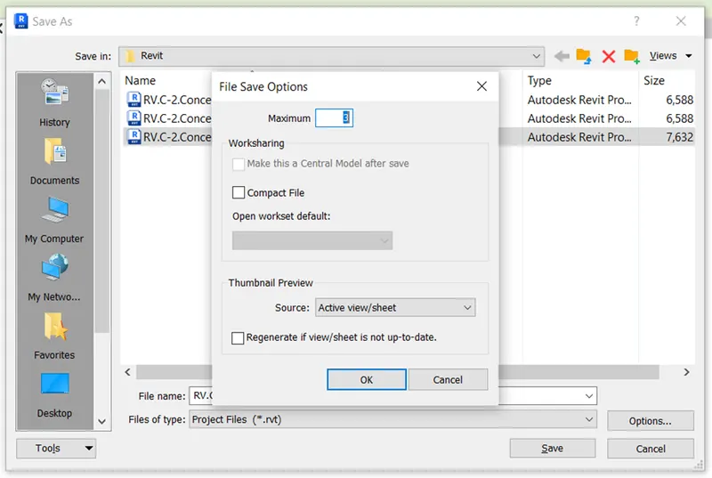
To Set up a project file with architectural template with units to Imperial / Metric. And to Complete the project information under Manage tab. Set up the maximum backups for project file to 3
Procedure:
With the Above created architecture imperial profile save as with following details
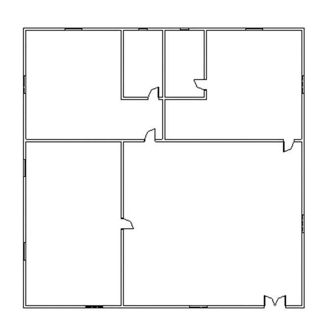
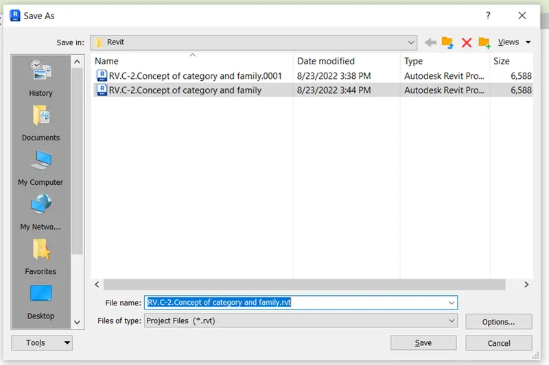
Go to manage tab and select project information

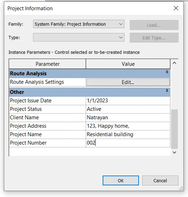
And give project information as follow
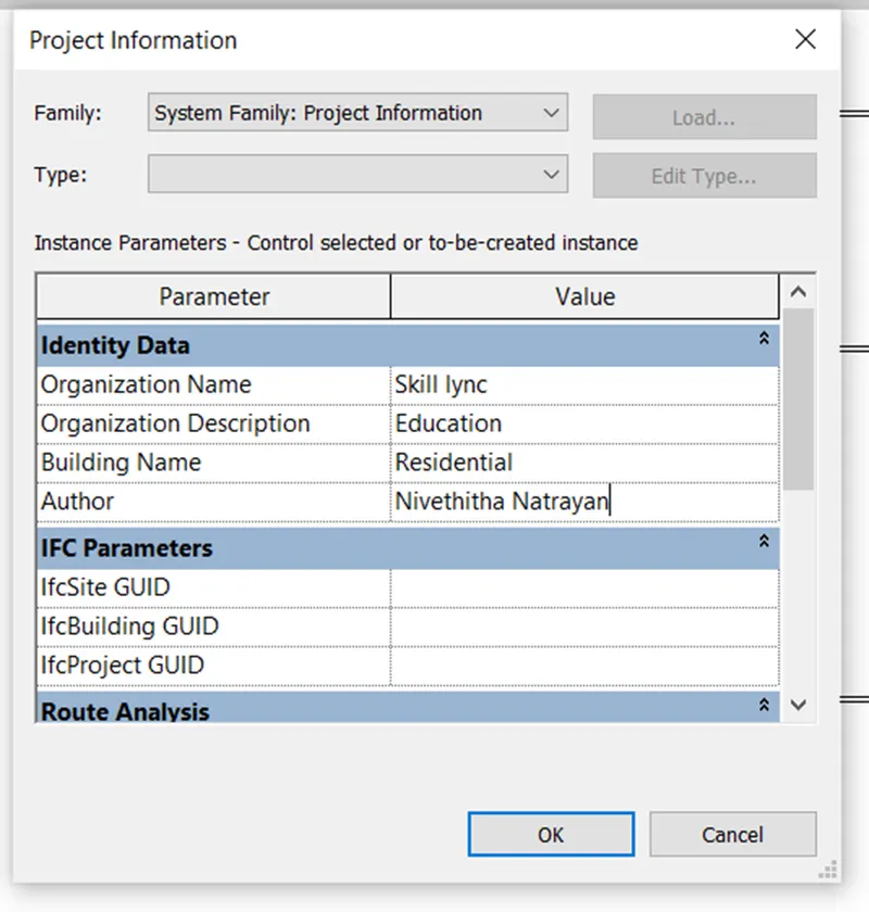
And click ok
To Set up the maximum backups for project file to 3
Go to file select save as and click project which will open a save as dialog box select option and give backup number as 3
Result:
Hence the result is obtained.
- Aim:
To create level and grids with the spacing of 10’ in Revit software.
Levels:
Levels are finite horizontal planes that act as a reference for level-hosted elements, such as roofs, floors, and ceilings.
Grids:
Grids are annotation elements that help organize your design.
Procedure:
- Open Architecture- Imperial template
- Select elevation view
- Select Architecture tab and select level
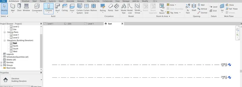
- Give offset distance as 10’ and select the top exiting line and move up
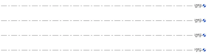
- Click the level and rename as shown below
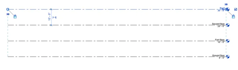
- Go to floor plan and select Architecture tab and select Grid

- Give offset distance as 10’ for transverse grids and 20’ for longitudinal grids.
- Select line and draw the first grid on both side and then select pick line and give offset distance as mentioned above and create grids as shown below
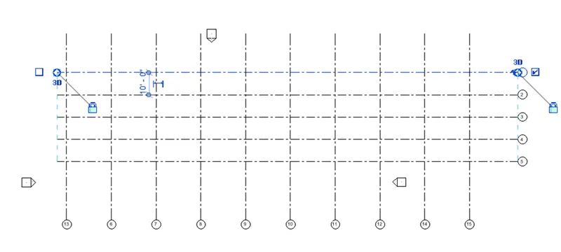
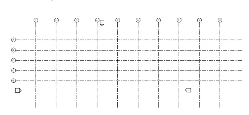
- Select the check box on the left and top
- Double click and give the name of the grids as follow
- Result:
- The result is obtained by the above steps
- Aim:
To create a 3D modelling of residential unit.
Procedure:
- Open a new Architectural-Imperial template and save the project with a name as Residential building.
- Go to Manage tab and click project information and give information of the project.
- Select level 1 and go to Architecture and select floor Architecture and draw 52’x52’ dimensional floor using line command
- Select wall and give follow properties as follow and draw the exterior wall on top of it
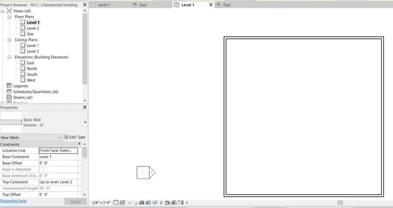
- Create a floor plan
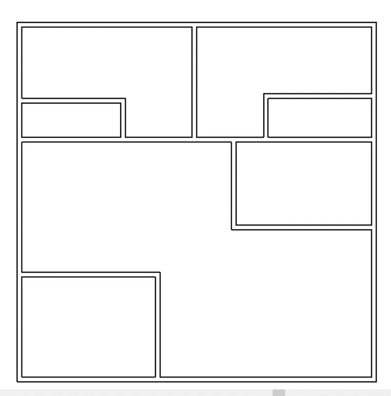
- Go to Architecture tab and select door and click load family and select the door as desired and its type
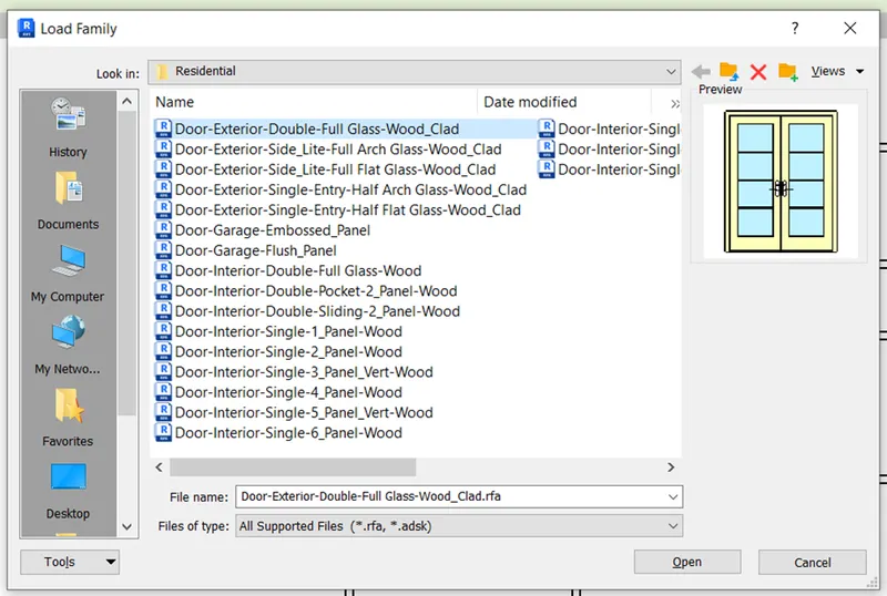
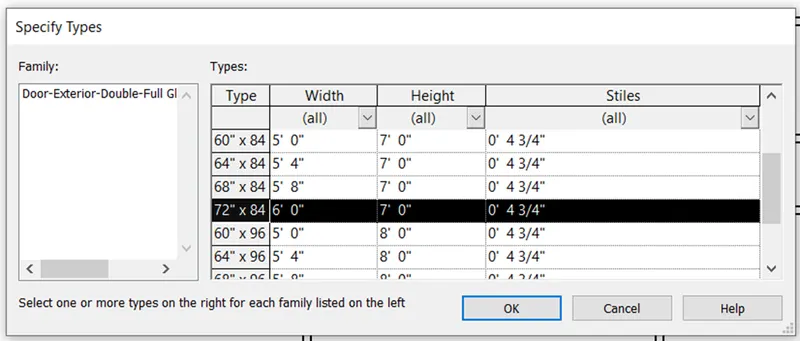
- By following the above steps place all the doors and window
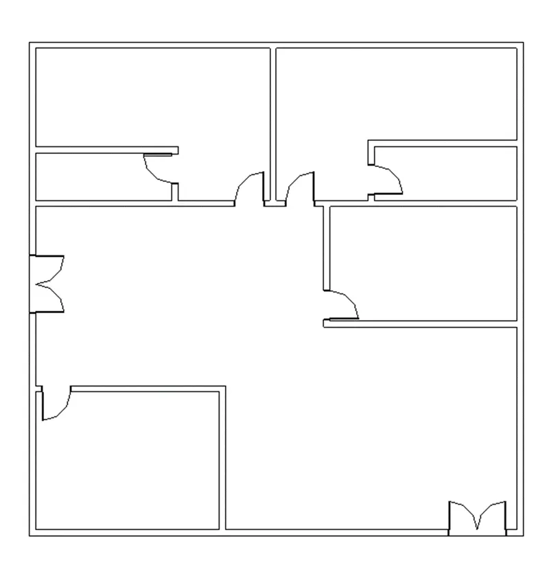
- By the same procedure place the windows from the family
- Result:
- The result is obtained by the above steps.
- Select 3D Realistic view
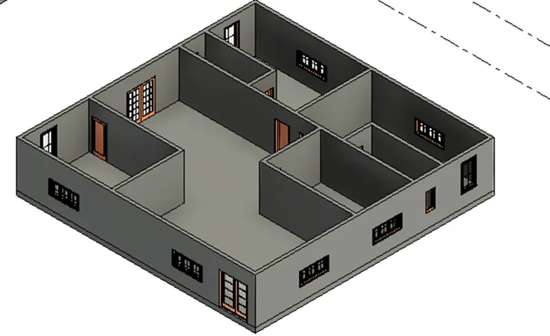
6.Aim:
To create dimensions for the above created layout.
Procedure:
Open the above created layout
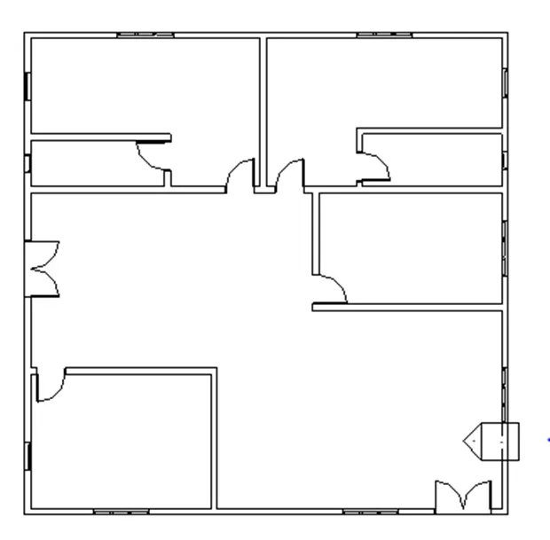
Click Annotate tab

Select linear dimension and click the opposite corners of a wall to create the dimension
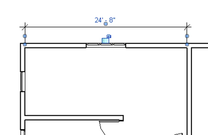
Go to Annotate tab and select Text and type the text.

- Result:
- The result is obtained by the above steps.
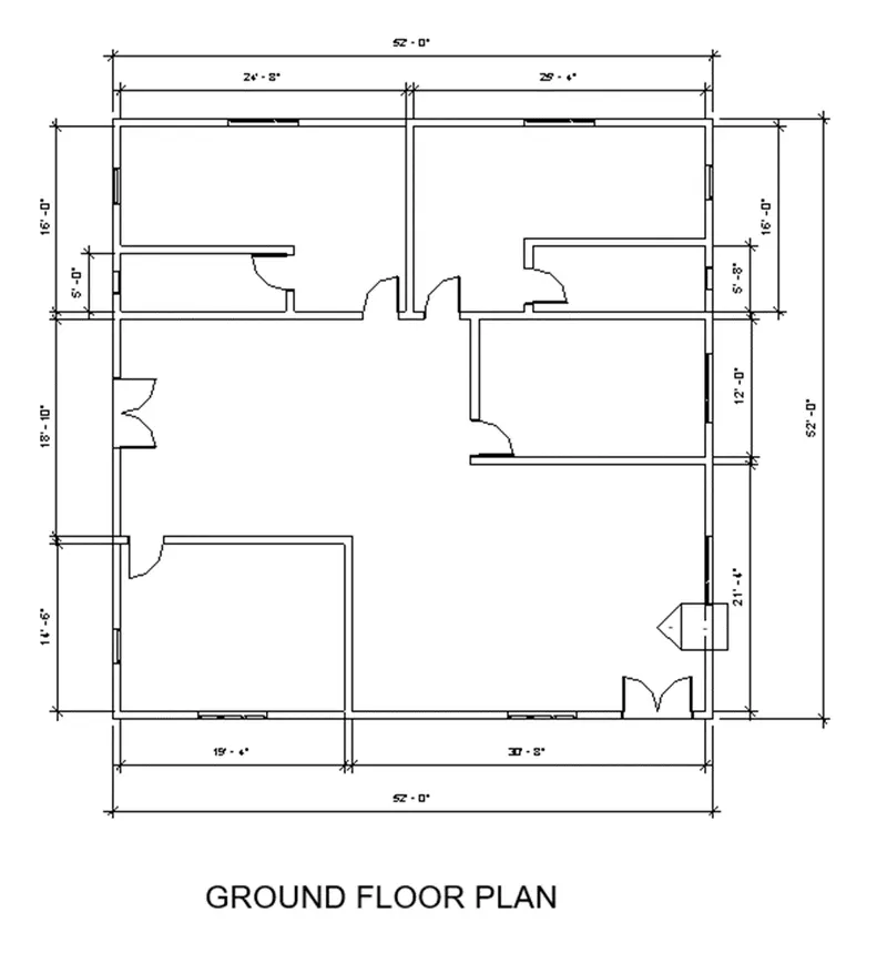
7.Aim:
To create the residential model elements such as Door, Windows, Tables, Chair, Couch, Bed, Lamps from the library and insert them to the model.
Procedure:
Open the existing plan which created earlier
Go to Architecture tab and select component and click place component then select load family.
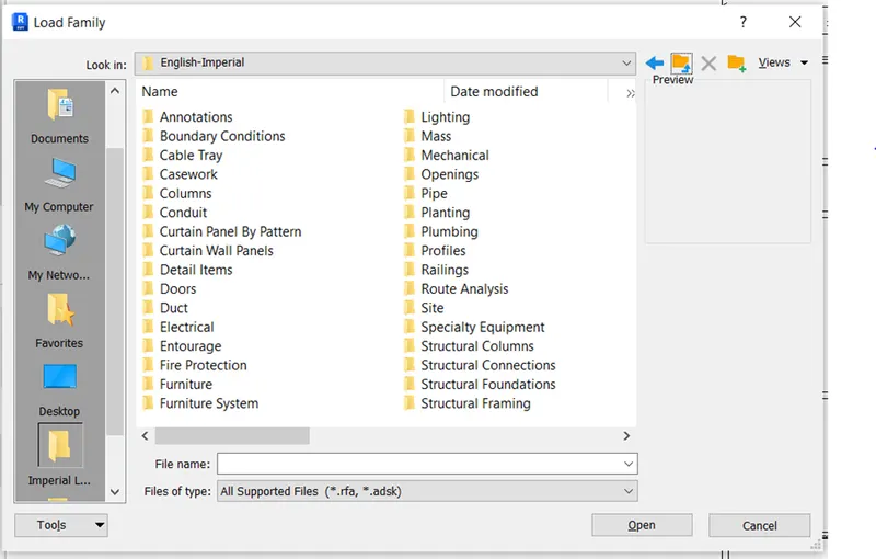
Select the category as Furniture
Click Beds as family
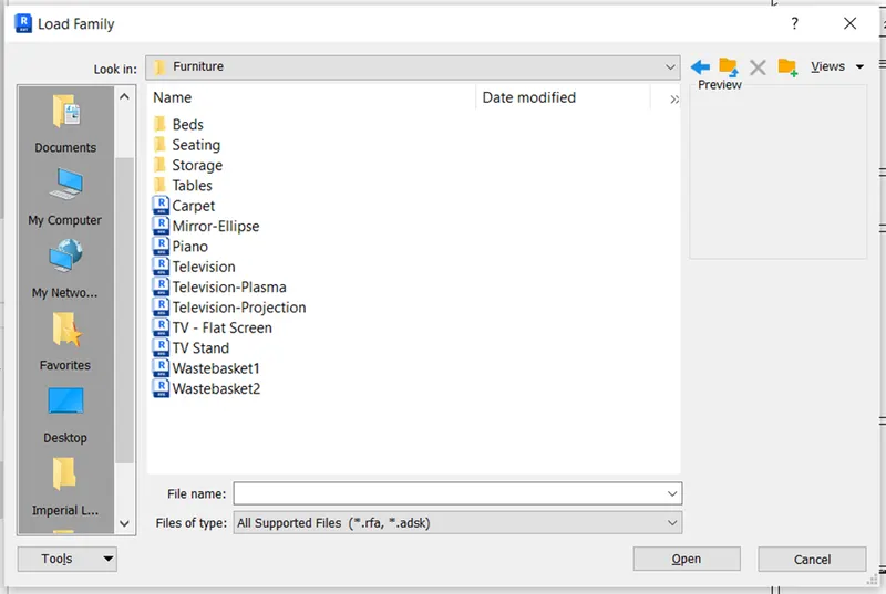
Choose a bed type
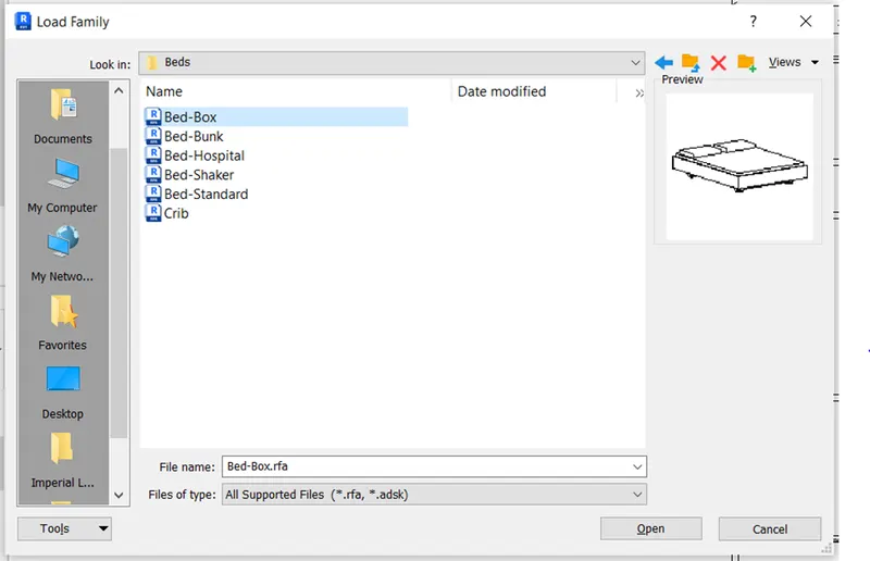
Place the Bed to the floor plan.
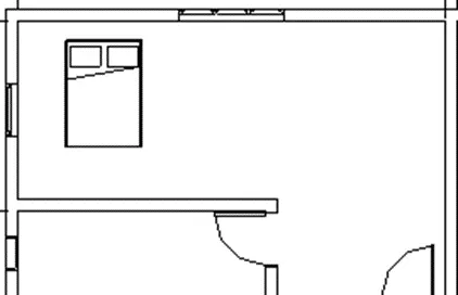
Follow the same procedure to place other elements like tables, Chair, Couch, Bed, Lamps from the library and insert them to the model.
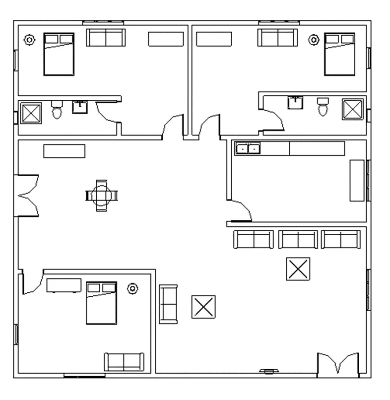
- Result:
- The result is obtained by the above steps