Creating Levels, Grids, Layout and model elements for a residential unit using REVIT
Q.1 What is BIM? Summarize the features of BIM and benefits of using BIM over 2D CAD tools.
ANS :-
Revit building elements are of three types:
- View elements
- Model elements
- Annotate elements
- Annotation elements
- Datum elements
BIM
BIM or Building information modelling is a process for creating and managing information on a construction project across the project lifecycle. One of the key outputs of this process is the building information model, the digital description of every aspects of the built asset.
Features of BIM
- Easy access to information
- Making the process more expressive
- Comprehensive view of the project
Benefits of using BIM over 2D CAD tools
- Complete representation
- Instant updates
- Time constraint
- Resource tracking
BIM integrates multi-disciplinary data to create detailed digital representation that are managed in an open cloud platform for real-time collaboration. Using BOM gives you greater visibility, decision-making more sustainable options and cost-saving on AEC projects.
Q.2 Understand the concept of categories, families, elements, instance in Revit. Go to insert Tab, choose a category. Pick a family and element. Understand the instance and insert it to Revit model
ANS :-
Category : A category controls the organization, visibility, graphical representation and scheduling of family within the project.
Family : A family is a grouping of 2D & 3D information that serves to represent a discrete building or documentation element in the project. It defines parametric, graphical and documentation requirements.
Type : A type is a specific representation of a type in the project defined by unique from other instances in the projects.
Instance : Instance is an individual representation of a type in the project by defined by unique parametric, graphical and documentation characteristics which it makes unique from other instance in the projects.
AIM :- To create a family in Revit
INTRODUCTION :- The instance like family & element in Revit is used to show the detailing in the drawing for the better prospective. Revit software is used to perform all the process for showing the load family & elements. Each steps are shown in the procedure section by showing the images & the command used for.
PROCEDURE :-
- Open Revit software
- Select template
- Now go to the insert tab as shown below

- Then click on LOAD FAMILY
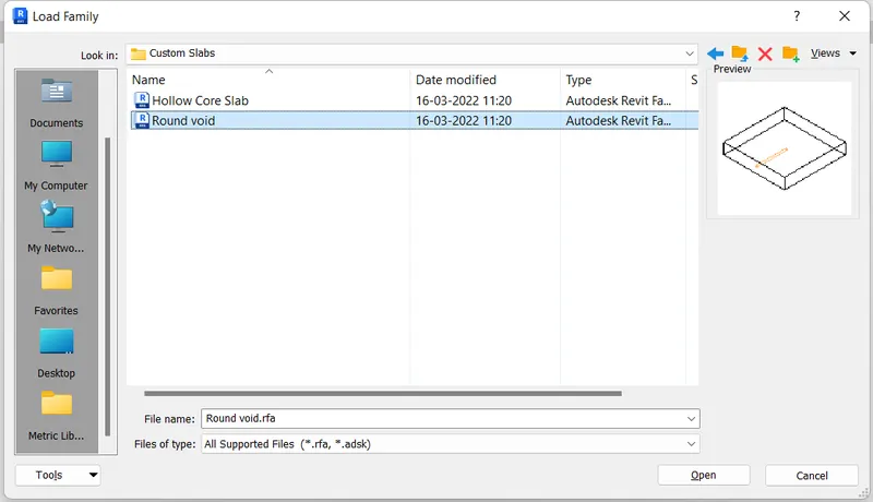
- Now from the dialog box select library
- Select English-imperial
- Then structural precast
- Then custom slab in the list
- Now click on the round void then open
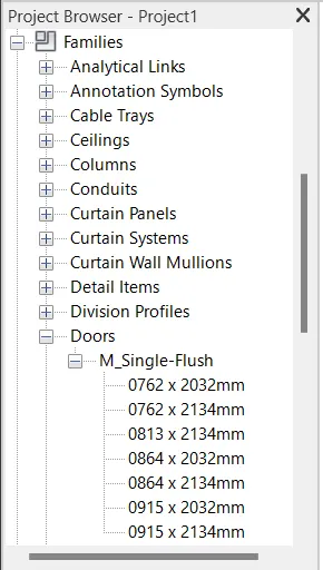
Family can also selected from the project browser
- Go to the project browser
- Now select the families from browser
- Now select any component whatever you want to insert
RESULT :- Understood the concept of categories, families, elements, instance in Revit. Used all the process what it asked in question section and got familiar knowledge about the all components.
Q.3 Setting up a project – open a project file with architectural template. Save the file with appropriate name. set up the project units to imperial / metric based on your convenience of modelling. Complete the project information under manage tab. Set up the maximum backup for projects file to 3
AIM :- Setting up a project – with the architectural template.
INTRODUCTION :- Set the project by the using architectural template in Revit software. The process what is asked in question is performed all the steps as asked & shown in the procedure section with image or each steps are shown.
PROCEDURE :-
- Open the Revit software
- Home page of Revit will appears
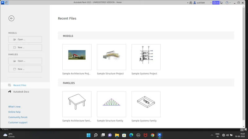
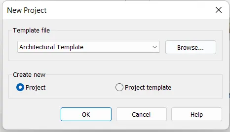
- Now click on NEW from the home page
- Dialog box will appears like shown below
- Select architectural template
- Then click okay
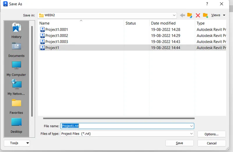
- Now go to the File
- Then select save as and name as project 1
- then click save
- now go to the manage tab
- click on project information
- this dialog box will appears
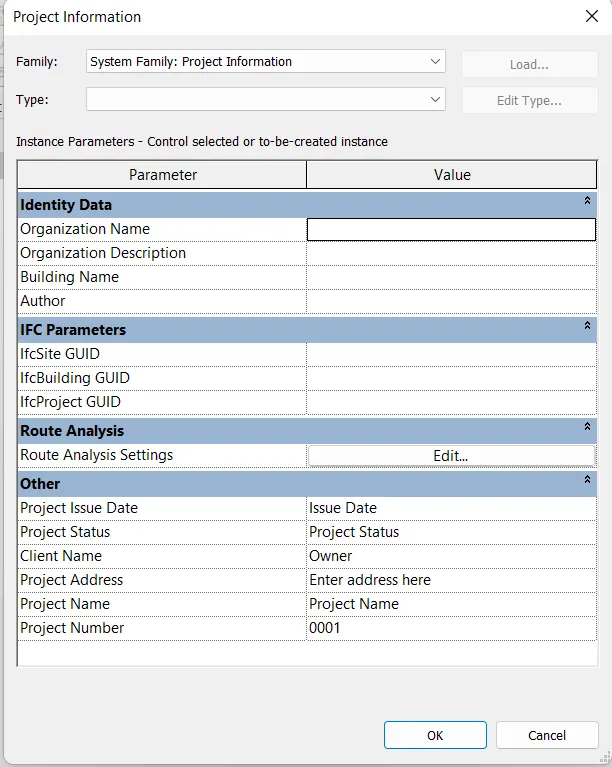
- then fill the box at own preference
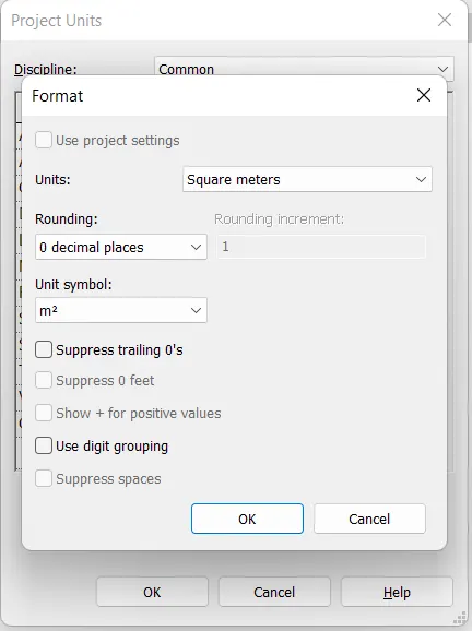
- then again go to the File tab
- select save as
- dialog box will appears
- there is an option called option
- select the option
- there you will have maximum backup option
- there select 3 then okay
- then select save
RESULT :-
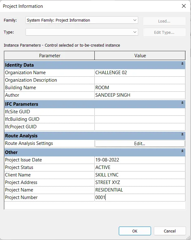
The project is saved with an appropriate name. and the by using all the procedure what said in question by the using of Revit software.
Q.4 Understand the concept of levels and Grid. Follow the naming and conventions. Create the following levels: ( convert to metric equivalents if metric is your units ) ground floor @0’ First floor @10’ Second Floor @20’ Roof @30’
Grid transverse grid A, B, C, D, E @10’ spacing
Longitudinal grid from 1 to 10 @ 20’ spacing
AIM :- To create levels and grids for standard layout
INTRODUCTION :- Grids & levels are used for the showing elevation of plan in the drawing. The grids & levels are created as asked in question by the use of Revit software.
PROCEDURE :-
- Open the Revit software
- Select the template as architectural
- Enter all the information and project units necessary
- Now go to the project browser
- Select the any elevation
- There is two levels are shown both are default
- Now rename 1st on as ground floor
- 2nd as first floor
- Now go to architectural tab
- Then select levels from right side of panels
- Now select the pick point
- Then enter offset distance as 10’
- Then pick the levels and create one by one 3 more levels
- Then rename them as A, B, C, D & E then enter
- Now go to the construction tab and click on GRID
- Create horizontally Grid at the offset distance value of 20’
- Create grids 1 to 10 for the section
RESULT :-
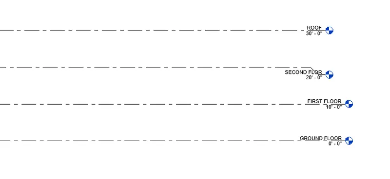
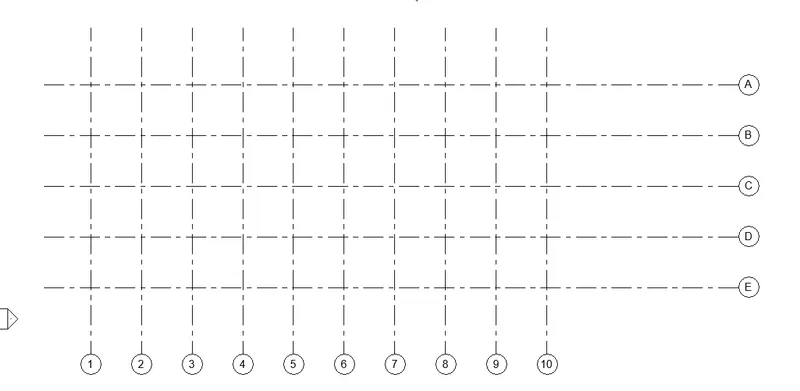
Grids & levels are created at distance of 10’ from A to E and the grids are 1 to 10 at distance of 20’.
Q.5 3D modelling of residential unit – from looking at your house or a place you aspire. Create a conceptual layout of the residential unit. You can measure using a tape or you can access your residential plan to create a similar layout.
AIM :- To create 3D modelling of layout
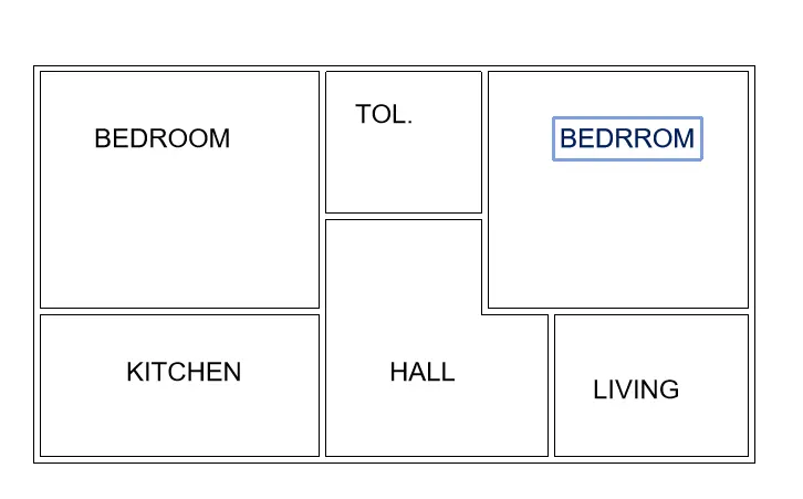
INTRODUCTION :- The layout is created at 70’ for horizontal side & 40’ for vertical side by the using appropriate tools and command in Revit software.
PROCEDURE :-
- Open the Revit software
- Select the template as architectural
- Create layout
- By the using architectural tab
- Then click on wall tab
- Then select line tool
- Now draw line to 70’ horizontally
- Then vertically 40’ draw line
- Same for the completing rectangle
- Now by the use of line tool create rooms appropriately
RESULT :- Layout of residential building is created by the use of line tool under the wall and architectural tab.
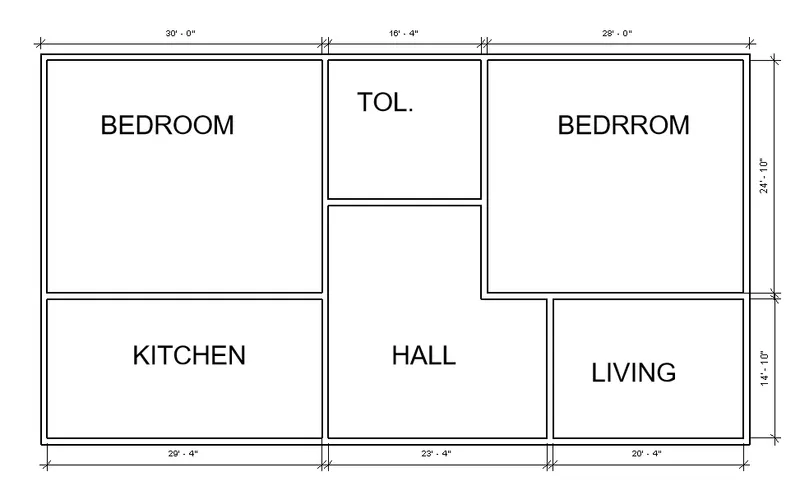
Q.6 In the layout created draft the level of details you are planning to include dimensions of room, components your plan to add in the residential unit.
AIM :- To create the draft the level of details and show the dimensions of residential plan.
INTRODUCTION :- The layout is created at 70’ for horizontal side & 40’ for vertical side by the using appropriate tools and command in Revit software. And the dimensions are shown by the using annotate tab under the ribbons. Dimensions of layout is shown by the use of Revit software all process is shown briefly in procedure section.
PROCEDURE :-
- From the last question
- Select annotate tab on ribbon
- Select dimliner
- And select the corner of the wall and show the all dimensions
RESULT :- Layout of residential building is created by the use of line tool under the wall and architectural tab. By the using of annotate tab the dimensions of layout is shown.
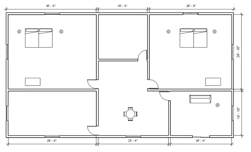
Q.7 Identify the residential model elements such as door, windows, tables, chairs, couch, bed, lamps from the library and insert them to the model. Save the project for use for assignment 3
AIM :- To insert the all components in the layout.
INTRODUCTION :- The layout is created at 70’ for horizontal side & 40’ for vertical side by the using appropriate tools and command in Revit software. The components like door, windows, tables, and lamp, chairs are inserted by the use of load family tab.
PROCEDURE :-
- From the last of the question
- Go to architectural tab then select door
- Then go to load family then select any type of door from library
- Then insert it by using the curser at where you need doors
- Same thing for the inserting windows
- And also for the bed, lamp, table & chairs also
RESULT :- Layout of residential building is created by the use of line tool under the wall and architectural tab. Inserted the all component which are required in questions by the using of Revit.
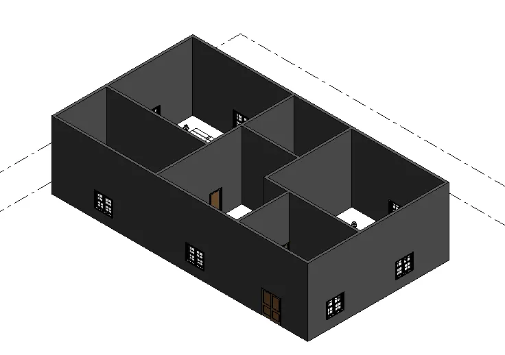
3D VIEW OF THE LAYOUT OF RESIDENTIAL PLAN