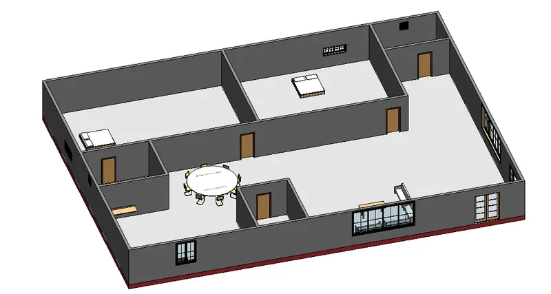
Creating Levels, Grids, Layout and model elements for a residential unit using REVIT
- 1) What is BIM? Summarize the features of BIM and benefits of using BIM over 2D CAD tools.
A) Building Information Modeling (BIM):
- BIM is an acronym for Building Information Modeling or Building Information Management.
- It is a highly collaborative process that allows architects, engineers, real estate developers, contractors, manufacturers, and other construction professionals to plan, design, and construct a structure or building within one 3D model.
- It can also span into the operation and management of buildings using data that building or structure owners have access to (hence the Building Information Management).
- This data allows governments, municipalities, and property managers to make informed decisions based on information derived from the model even after the building is constructed.
Features of BIM:
- BIM is a physical representation of the physical and functional characteristics of the building process, that provides every minute detail of the project.
- Every stakeholder makes their discipline-specific input to make it a comprehensive shared information resource about the structure. • One can easily access the right information at the right time that provides a reliable basis for decision making during a structure's entire lifecycle.
- BIM models not only present 3D geometric view of the structure, they provide a more comprehensive overview of the entire building process.
- It covers every component of this process from geometrical aspect of the design to spatial relationships,from light analysis to provision of various services,from topographical information to quantities or properties of building components, and so on.
- BIM design tools allow you to obtain various views from a building model and produce high-quality, accurate drawings. These views are based on a single definition of each object and thus gives a more realistic and accurate idea of the final structure.
Benefits of using BIM over 2D CAD tools:
- Three-dimensional Building Information Modeling (BIM) provides many advantages over 2D CAD due to the vast capabilities of parametric modeling.
- All components modeled in 3D BIM software contain real world information about that component.
- For instance, if you were to place a wall within a BIM model, that wall would automatically include information about it such as its length, width, volume, weight, etc. with little to no additional input from the user. Because of this, once the 3D model is complete the information can quickly and easily be translated into schedules, drawings, and much more.
2) Understand the concept of Categories, Families, Elements, Instances in Revit. Go to Insert Tab, choose a category. Pick a family and element. Understand the instances and insert it to Revit model.
A) First we need to understand the concept of the Categories, Families, Elements, Instances in Revit, we discuss on by one below.
- We select the Categories, Families, Elements, Instances by selecting the load family in the insert toolbar.

- CATEGORIES:
- Classification for families, for example doors, curtain walls, furniture, lighting fixtures, and so on.
- Families are grouped and sorted by category in the content libraries and in the Project Browser.
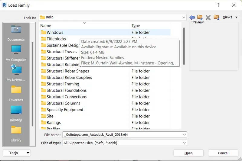
- FAMILIES:
- A family is a group of elements with a common set of properties, called parameters, and a related graphical representation.
- Different elements belonging to a family may have different values for some or all of their parameters, but the set of parameters (their names and meanings) is the same.
- All of the elements you use in Revit are families. Some families, such as walls or level datums, are included in the model environment.
- Other families, such as specific doors, or fixtures, need to be loaded into the model from an external library. You can't create anything in Revit without using a family.
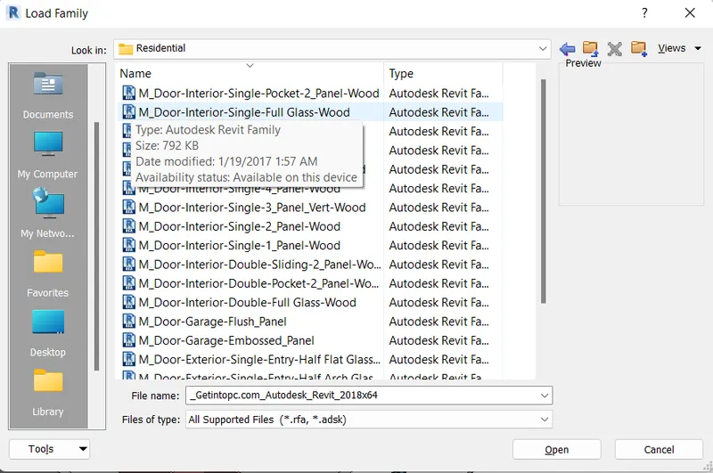
- ELEMENTS:
- Elements are the building blocks of a 3D model.
- They represent the real-world components that a designer adds to the model.
- Some elements such as walls, windows, and beams are 3D and appear in all views.
- You can think of these elements as components that exist in a building.
- Other elements such as tags, dimensions, or other annotations appear only in the view in which they are placed.
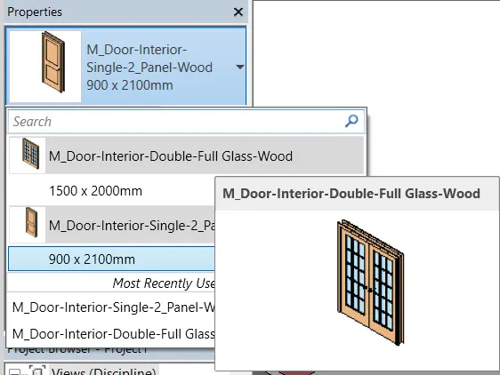
- For example we select the family from the door catagory, after selecting the family the new tab will visible.
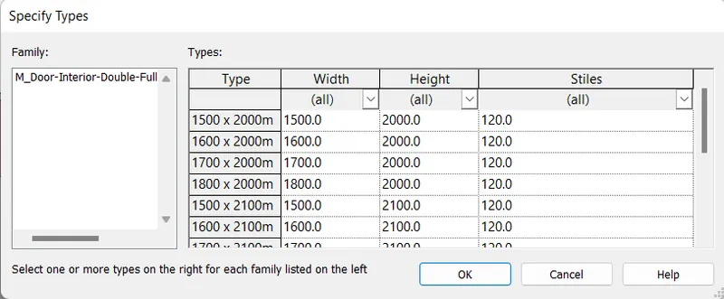
- Next there will be different sizes of door is there, select any one of them.
- Next that element is applied to the 3d model, and it will appears in the properties tab at the left side of the screen, as shown below.
- INSTANCES:
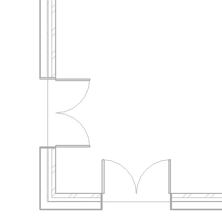
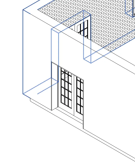
- Instances are individual graphical/geometric elements placed in a Revit model e.g. a single Wall, or a single Door, or any other single element.
- As a subset of Revit Elements, Instances inherit a series of Parameters from their Category and Type and might have instance parameters as well that only belongs to that single instance.
- The single element attatched to the wall is door, that door we call as instance, as shown below.
3) Setting up a Project - Open a project file with architectural template. Save the file with appropriate name. Set up the project units to Imperial / Metric based on your convenience of modelling. Complete the project information under Manage tab. Set up the maximum backups for project file to 3.
AIM:-
Setting up a Project in the Revit software.
INTRODUCTION:
- For setting a project. we need to select the architectural template for modeling the architectural plan.
- When we save the file with appropriate name, the name will be saved to the particular folder.
- The project units toolbar is used to set the project units, that applies to the whole project.
- The project information option is used to save the information of the project, by entering the project name, project issue date, project status, project address etc.
PROCEDURE:
Step:-1
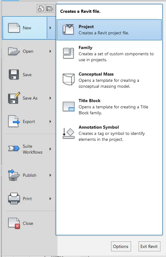
- First select the file tool bar, then the new tab appears and select the new option and then select the project.
Step:-2
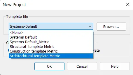
- Select the architectural template in the new project tab and click Ok.
Step:-3
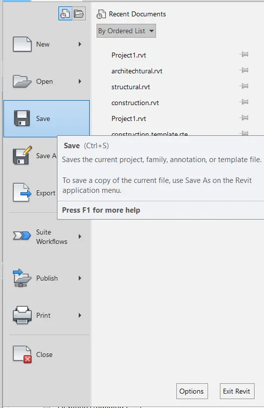
- After the project is done, open the file toolbar and select the save option.
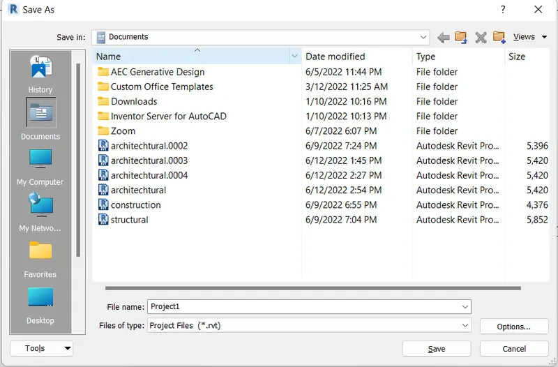
- After selecting the save option the new tab will visible.
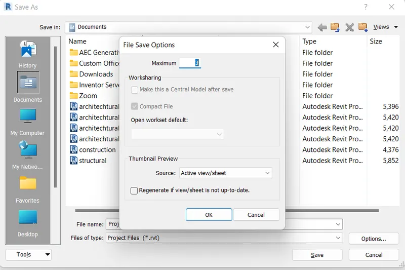
- Enter the new name, and before saving the name of the project, click on the options at right corner of the save as tab, as shown below.
- Next we need put maximum backups for project file to 3.
Step:-4
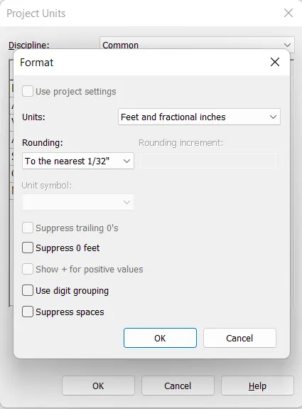
- Next we need to select the project units in the manage tool bar.
- Next put the units to Feet and fractional inches, as shown below.
Step:-5
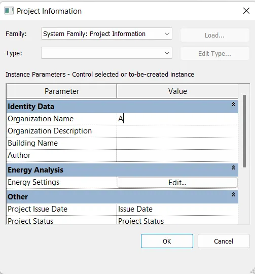
- Next we open the manage toolbar and then select the project information.
- After selecting the project information, the new tab will be visible, then enter the project details in the project information tab as shown below.

Result :-
The setting up of the Project is done in the Revit software, in the Detailed manner.
4) Understand the concept of Levels and Grids. Follow the naming and conventions. Create the following Levels: ( Convert to metric equivalents if metric is your units)
Ground Floor @ 0’
First Floor @ 10’
Second Floor @ 20’
Roof @ 30’
Grids Transverse Grids A, B,C,D, E @ 10’ spacing
Longitudinal Grids from 1 to 10 @ 20’ spacing
AIM:-
To create the grids and levels using the given details.
INTRODUCTION:
- Grid lines are finite planes, We can drag their extents in elevation views so that they do not intersect level lines.
- This allows you to determine whether grid lines appear in each new plan view that you create for a project.
- Grids can be straight lines, arcs or multi-segmented. You can hide grid lines after you add them.
- Use the Grid tool to place column grid lines in the building design.
- We can then add columns along the column grid lines.
- As we start to construct our 3D model, we need some method of controlling the vertical height of our elementsbe it floor heights, the base and top of columns, window cill heights, etc. This is where Levels come into play. In order to create an effective and efficient model, it is crucial that you understand the use of Levels. The correct use of Levels will ensure that your model can readily be adjusted with the minimum of effort.
PROCEDURE:
Step:-1
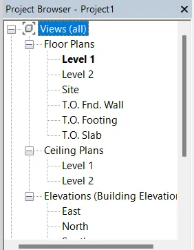
- For creating the levels, first we select the levels in the project browse.
Step:-2
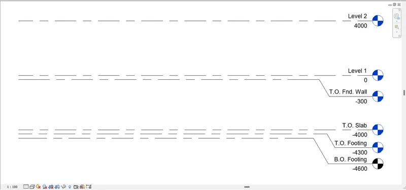
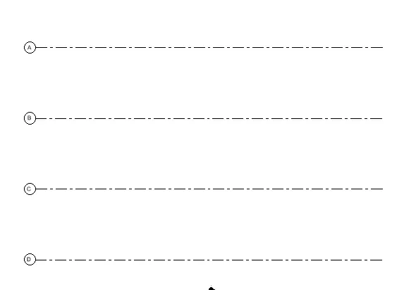
- Next the levels will be displayed on the screen, as shown below.
Step:-3
- Next we draw the grid lines horizantally, indicating the grids with A, B, C, D.
Step:- 4
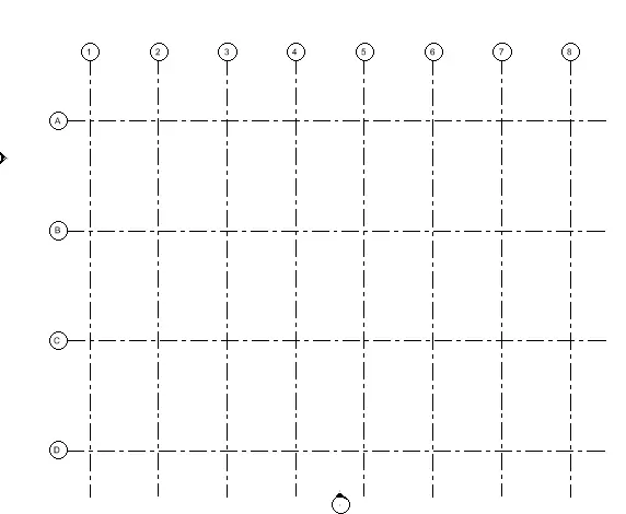
Next we has to draw the vertical grid lines on the horizontal grid lines name it as 1 to 8.
Result :-
The levels and grid lines are drawn sucessfully in the revit software in detailed manner.
5) 3D modelling of residential unit – From looking at your house / or a place you aspire. Create a conceptual layout of the residential unit. You can measure using a tape or
you can access your residential plan to create a similar layout.
AIM:-
To create a conceptual layout of the residential unit in the revit.
INTRODUCTION:
- Three-dimensional (3D) models represent a Physical body using a collection of points in 3D space, connected by various geometric entities such as triangles, lines, curved surfaces, etc.
- Being a collection of data, 3D models can be created manually, or by scanning.
- Their surfaces may be further defined with texture mapping.
PROCEDURE:
Step:-1
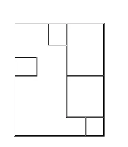
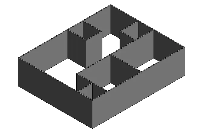
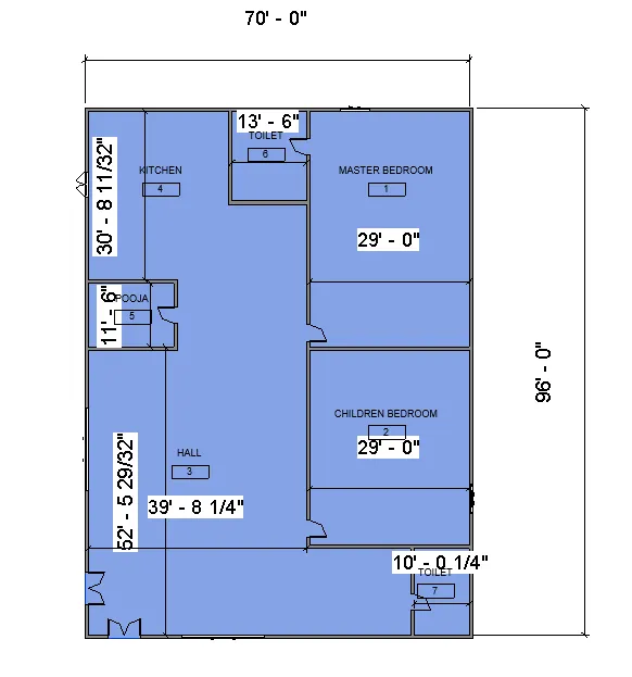
First we have to draw the residential layout with the standard dimensions, as shown in the below figure.
Step:-2
- Next we change the visibility as shaded as shown in the figure given below.
Step:- 3
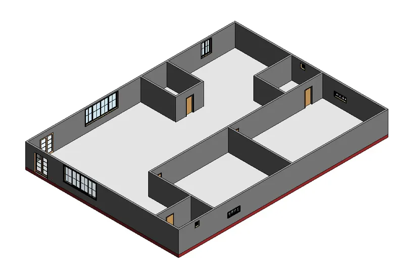
Next change the residential view to the 3D view as shown in the figure given below.
Result :-
The conceptual layout of the residential unit is created sucessfully in the revit software in detailed manner.
6) In the layout created draft the level of details you are planning to include – Dimensions of room, components you plan to add in the residential unit.
AIM:-
To draft the level of details which include dimensions of room, components to add in the residential unit.
INTRODUCTION:
- Dimensioning on a floor plan usually requires two or three continuous dimension lines to locate exterior walls, wall jogs, interior walls, windows, doors, and other elements.
- Exterior walls of a building are dimensioned outside the floor plan. The outermost dimension line is the overall building dimension.
- The next dimension line, moving toward the plan, indicates wall locations and centerlines to doors and windows.
- Other miscellaneous details in the plan are located on a third dimension line.
PROCEDURE:
Step:-1
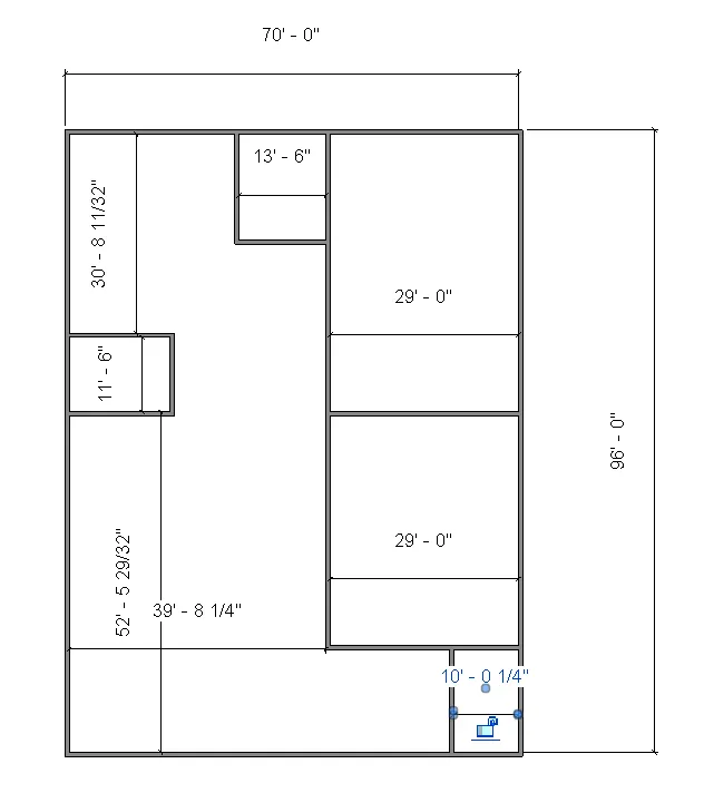
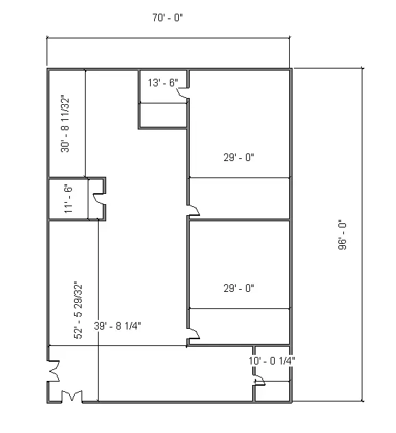
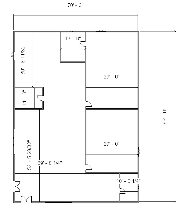
- From the previous drawn residential unit, we put the dimensioins for the rooms, as shown below.
Step:- 2
Next we need to add the doors and windows
in the layout using doors option in the architectural tool bar.
Step 3:-
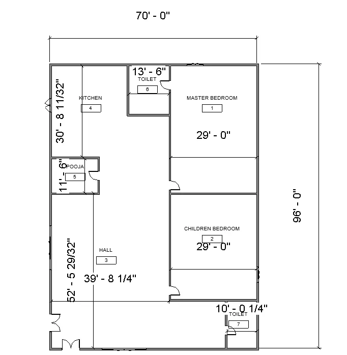
Next add the room names in the layout created in the revit.
Step:- 4
Next we use the floor option to create the floor in drawn layout.
Step:- 5
Now change the residential view to 3D view in the layout which was drawn in the revit.
Result :-
The layout is created draft the level of details you are planning to include – Dimensions of room, components you plan to add in the residential unit in the revit software in detailed manner.
7) Identify the residential model elements such as Door, Windows, Tables, Chair, Couch, Bed, Lamps from the library and insert them to the model . Save the project for use
for Assignment 3
AIM:-
To insert the residential model elements such as Door, Windows, Tables, Chair, Couch, Bed, Lamps from the library to the model. Need to save the project for use.
INTRODUCTION:
- The residential model elements are door, windows, chair, couch, bed, lamps.
- These elements are very important in the building model for construction.
- Comming to the 3d modeling in the revit, these elements are present in the library and we need to insert them into the model.
PROCEDURE:
Step:-1
- Next we need to add the doors and windows to the layout using the door option in the architecture toolbar.
Step :-2
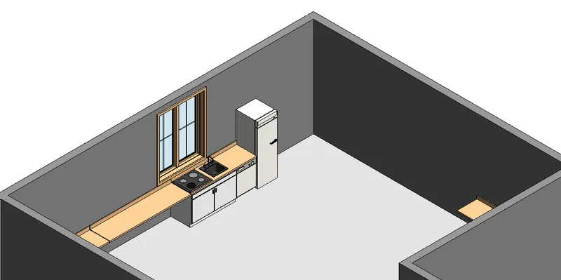
Next insert the kitchen items in layout using components toolbar in revit.
Step :-3
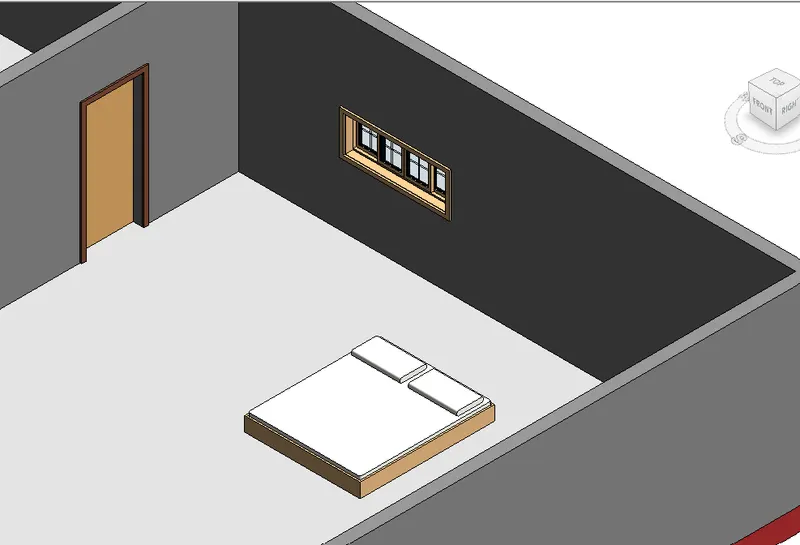
Next add the bedroom materials in the layout using components in the revit.
Step:- 4
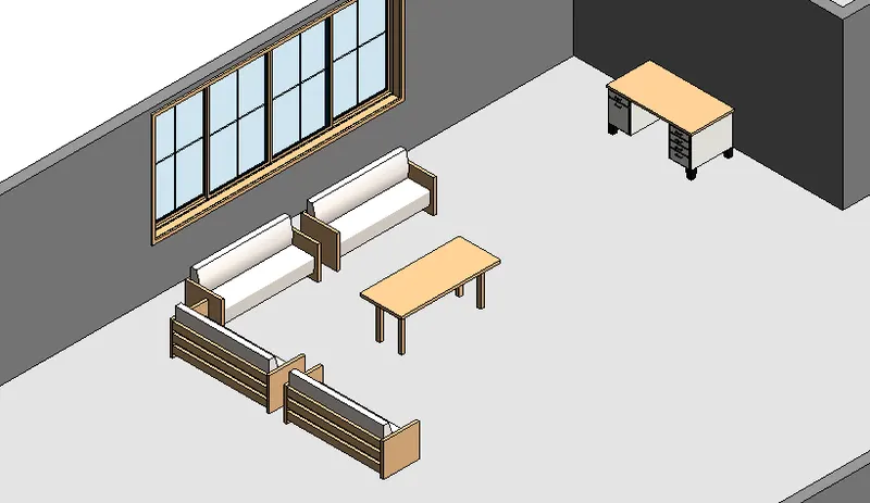
Now add the hall materials in the layout using components in the revit.
Step :- 5
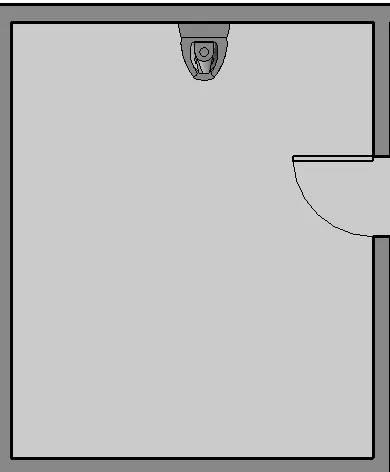
Now add the bathroom components in the layout using revit liberaries.
Step :-6
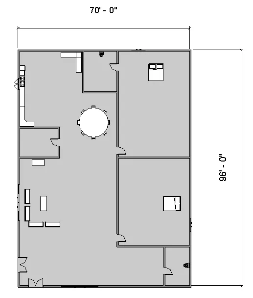
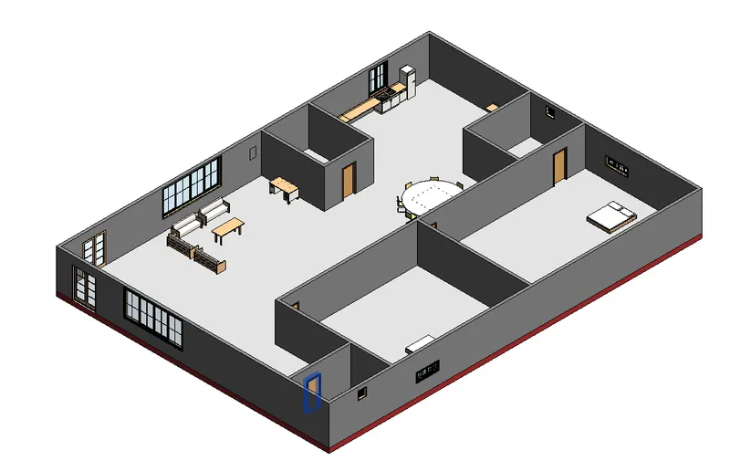
Added the residential model elements such as Door, Windows, Tables, Chair, Couch, Bed, Lamps from the library and insert them to the model.
Result :-
The main aimof the challenge is to add the residential model elements such as Door, Windows, Tables, Chair, Couch, Bed, Lamps from the library and insert them to the model.