Creating Levels, Grids, Layout and model elements for a residential unit using REVIT
Question1) What is BIM? Summarize the features of BIM and benefits of using BIM over 2D CAD tools.
Answer.
BIM:
- BIM is a Building Information Modeling.
- It is a concept that is created by the Autodesk.
- It is a software or computation tool that helps us achieving BIM as a process.
- Mainly BIM is divided into two concepts i.e, Coordination and Computation.
- It helps in achieving the co-ordination between the multiple disciplines.
- Different peoples came together to work on a single project using BIM software.
- BIM helps us in computation such as materials,schedule,quantity schedule or to perform the energy analysis or evaluation.
- It helps us in achieving the co-ordination and computation as a part of our modelling process.
- In BIM,Building Information Modelling the Information part is governed by co-ordination and computation.
- So we need to focus more in detail upon the co-ordination and computation so that we can gather as much information as possible of our project.
Benefits of BIM over 2D CAD tools:
- Using BIM over 2D CAD tools is highly time saving software. It also saves the cost and resources.
- It improves the communications and coorrdination between the client and the engineers and between the working professionals.
- BIM software have higher quality result than 2D CAD tools.
- It has shorter project lifecycle than the 2D CAD.
- BIM offers a complete representation of a building's design.
- BIM can offer much more to the client but CAD tools don't have much to offer in comparison to BIM.
Question 2) Understand the concept of Categories, Families, Elements, Instances in Revit. Go to Insert Tab, choose a category. Pick a family and element. Understand the instances and insert it to Revit model.
AIM: To understand the concept of Categories, Families, Elements, Instances in Revit.
INTRODUCTION: First of all let me tell you briefly about the categories, Families, Elements and Instances in Revit.
Firstly lets understand what is:
Categories: Categories is one of the revit element hiearchy. It controls the organisation,visibility, the graphical representation and scheduling options of families within the project.
Family: It is a group of 2D and 3D information that serves to represent the documentation element of the project. It desines the parametrical, graphical and documentation also.
Type: Specific representation in the family is defined by distinct parameter graphical and documentation characterstics which makes it unique from the other types in the family.
Instances: Individual representation of a type in a project defined by unique parameteric,graphical and documentation characterstics.
PROCEDURE:
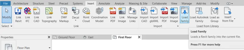
- First of all click on the Insert tab, in that there is an option called Load family click on that option as shown in the below figure.
- After clicking on the Load Family option. There is a dialouge box whic opens up as shown in below image:
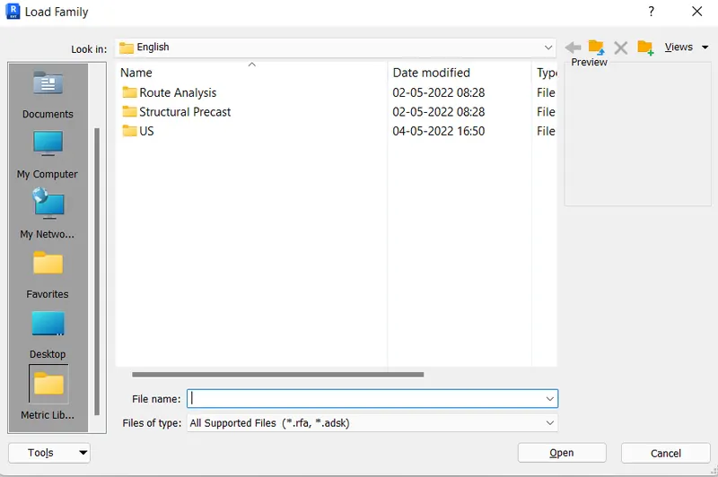
- In this dialouge box then double click on the option US. Then another dialouge box opens.
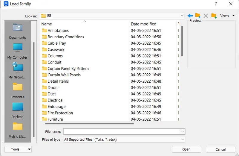
- After this window opens up, now double click on the category which you want to add in your project.
- And to preview a single family in that window simply just click on the family and the preview will appear on the left side on the screen as shown in the below figure.
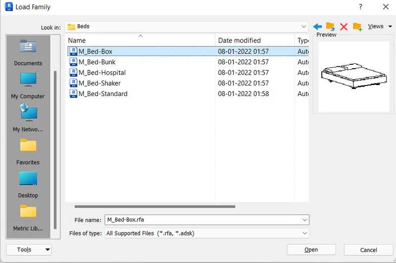
- And to load a family click on the family and then click on the option Open.
- Then the family is loaded on our project.
- For example i have to load beds in my project then just Go to the Insert tab, in insert tab click on the load family option and then after that click on the library which we have downloaded i.e, US and after that various categories are present in that file. And then click on the required family i.e, bed and then press the option OPEN.
Question 3) Setting up a Project – Open a project file with architectural template. Save the file with appropriate name. Set up the project units to Imperial / Metric based on your convenience of modelling. Complete the project information under Manage tab. Set up the maximum backups for project file to 3.
AIM: To open a project file with the architectural template. And to save the file with the appropriate name.
INTRODUCTION: To understand the concept of the opening a project file with the architectural template and how to save a file, change the units or sets the units with the appropriate name using the save as option provided in the Revit software. And to understand the concept of project information.
PROCEDURE:
To Open a project file with the architectural template.
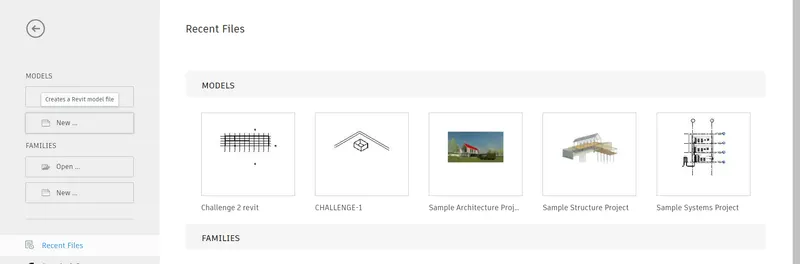
- To open a project file in the Revit software first of all open a Revit software 2023. After opening the Revit software just click on the Newb option as shown below in the figure:
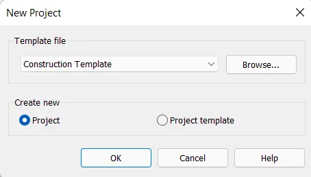
- After clicking on the New option a new window opens named as New Project. In that dialouge box select the Architectural template and then click OK,if the Architectural template is not there then click on the option Browse just as shown in the below figure:
- Now in the choose template dialouge box search for the architectural imperial file . Here default is the imperial file.
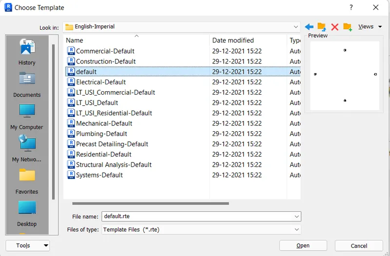
- Now click Open.
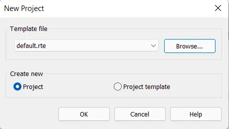
- Now click on the OK option.
- Now the new project with the architectural template is created.
To save the created file:
- Now go to the file option click on the Save As option and then click on the project.
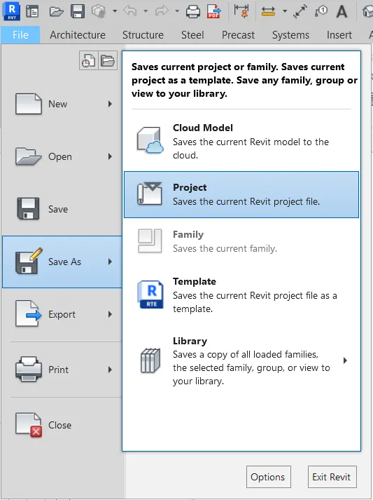
- Now click on the option OK.
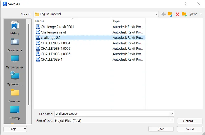
- So the file name is changed to CHALLENGE 2.0.

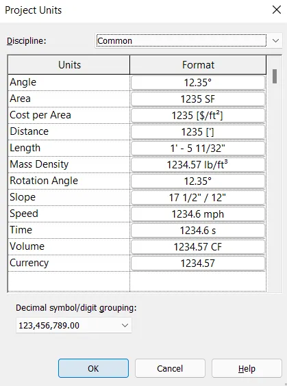
- Type UN and then press enter. A new dialouge box appears on the screen as shown in the figure.
To create project information:
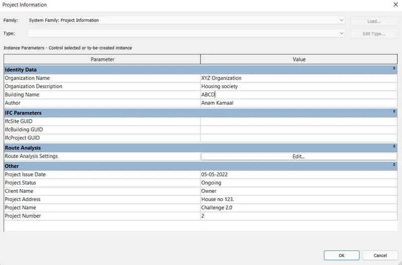
- Firstly click on the manage toolbar, we need to select the project information and enter the project details.

- After selecting the project information, a new window opens as shown in the below figure:
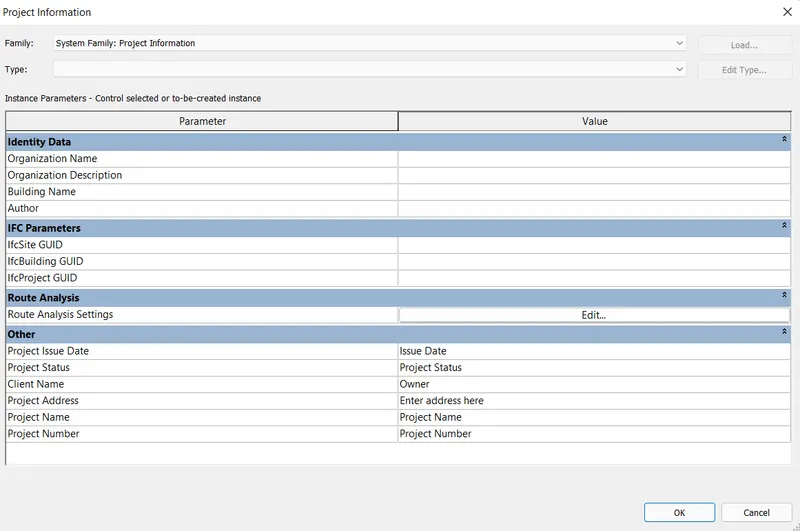
- Now we have to fill the required details related to the project in the project in formation window as shown in the below figure:
Question 4) Understand the concept of Levels and Grids. Follow the naming and conventions. Create the following Levels: ( Convert to metric equivalents if metric is your units)
Ground Floor @ 0’
First Floor @ 10’
Second Floor @ 20’
Roof @ 30’Grids Transverse Grids A, B,C,D, E @ 10’ spacing
Longitudinal Grids from 1 to 10 @ 20’ spacing.
AIM: To understand the concept of levels and grids.
INTRODUCTION: Levels and grids are the skeleton of the revit software. Levels and grids are usually used to indicate the location of the rooms,floors, foundation etc. We can draw columns and walls using grids.
PROCEDURE:
- First of all open the elevation of the project to add the levels on the project.
- Now click on the Architecture tab and in the architecture tab there is an option called Level click on that option.

- Now click on the drawing area and draw a level in a horizontal manner now click after reaching its ends.
- We have already given the two levels by the Autodesk Revit.
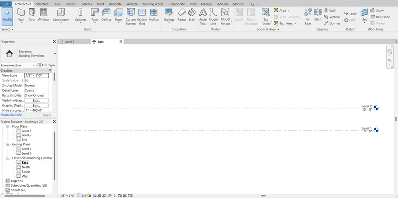
- It is named as the Ground level and the first floor.
- As for the other floors and roof go to the Architecture tab click on the Level option after clicking on the Level option a new box pops up as shown in the below option:
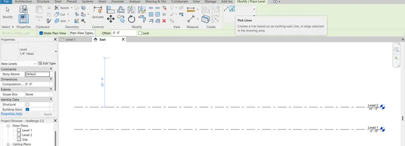
- From here click on the option pick up line and then give the offset of 10'-0".

- Now keep the cursor on the first floor and click in the upward direction and do the same procedure for the remaining floors.
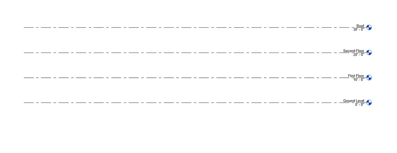
- Here is the result:
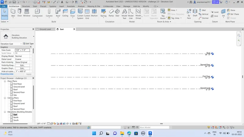
RESULT FOR LEVEL:
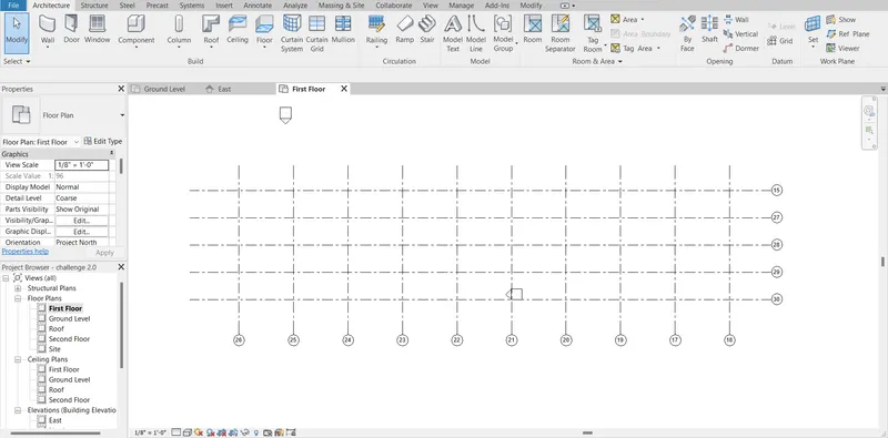
GRID LINES:
- For creating the grid lines go to the architecture option from there, there is an option named Grids on the left side of the drawing screen.
- After clicking on the grid line a new box pops up as shown in the below option:
- From here click on the option pick up line and then give the offset of 20'-0".
- Now keep the cursor on the left direction and click in that direction and do the same procedure for the remaining floors.
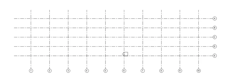
- Here is the result:
FINAL RESULT:
Question 5) 3D modelling of residential unit – From looking at your house / or a place you aspire. Create a conceptual layout of the residential unit. You can measure using a tape or
you can access your residential plan to create a similar layout.
AIM: To create a 3D modelling unit and to create a conceptual layout of the residential unit.
INTRODUCTION: 3D modelling enables us to visualize the structure in the very possible realistic image.
PROCEDURE:
- To create a 3D modelling residential unit in the Revit software, open a project.
- Click on the floor plan option and start drawing the floor plan in that section.
- To draw the walls click on the architectural tab and then click on the wall-architectural option.
- Draw the walls using the wall-architectural option.
- If you want to modify the wall then you can find the modify option in the property browser from there u can change the specification of the wall like the size of the wall the thickness of the wall etc.
- As you can see in the below image.
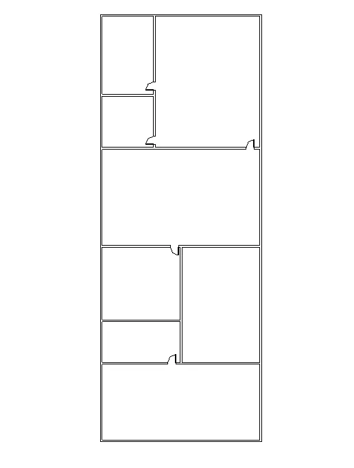
- And to view the 3D image of this plan just click on the view option and in the view option there is an option named 3D view just click on that and our 2D plan will convert into the 3D plan.

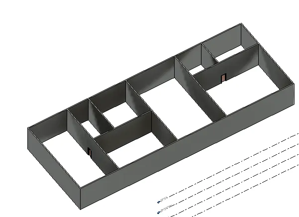
- This is the 3D view.
Question 6) In the layout created draft the level of details you are planning to include – Dimensions of room, components you plan to add in the residential unit.
AIM: To creating and adding the dimensions to the rooms and to add the components to the plan.
INTRODUCTION: In this we will learn to add the dimensions and the components in the plan by using the alignment tool and load families. In family option we have various options of components to put in our plan which makes our plan more realistic.
PROCEDURE:
- To align the plan using alignment tool, we have to click on the Annotate option from there we have to click on the aligned option.

- After clicking on the aligned option just take the cursor on the drawing screen and take the dimensions using the aligned tool. As shown in the below figure:
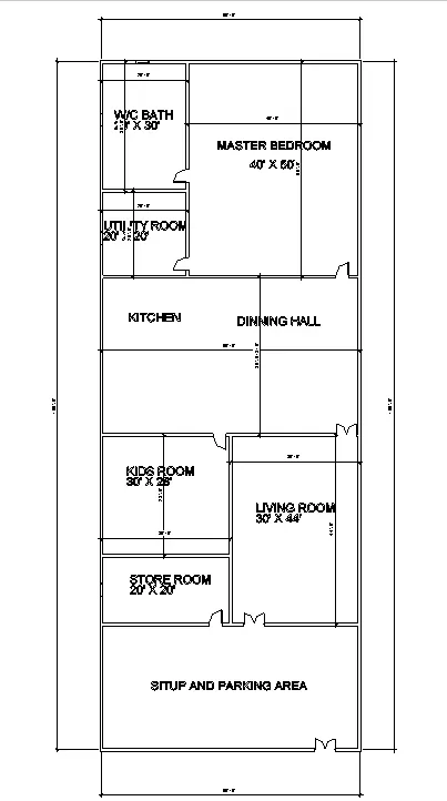
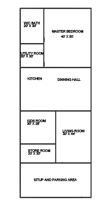
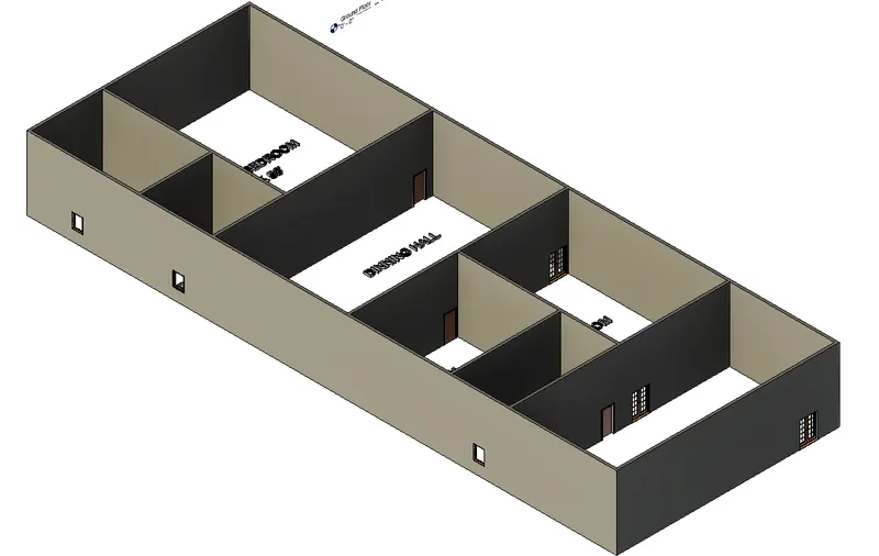
- Now to draw the doors and windows click on the architectural tab from there click on the option doors and windows according to your requirement and then place it in the desired location.
Question 7) Identify the residential model elements such as Door, Windows, Tables, Chair, Couch, Bed, Lamps from the library and insert them to the model . Save the project for use
for Assignment 3.
AIM: To identify the residential model elements such as Door,windows,tables,chairs,couch,bed,lamps from the library and insert them into the model.
INTRODUCTION: In this we will learn to add the dimensions and the components in the plan by using the alignment tool and load families. In family option we have various options of components to put in our plan which makes our plan more realistic.
PROCEDURE:
- Now we have to insert the furniture into our model using the loaded library. For this go to the insert option from there click on the Load family option.
- In the load family dialouge box, click on the category of the family which you want to use in your project.
- Before loading the family into our project we can see the preview of the family on the right side of the dialouge box.
- After selecting the family just click on the Open option.
- And now click on the Load component option in the architectural tab.
- Click the loaded family in the desired loacation.
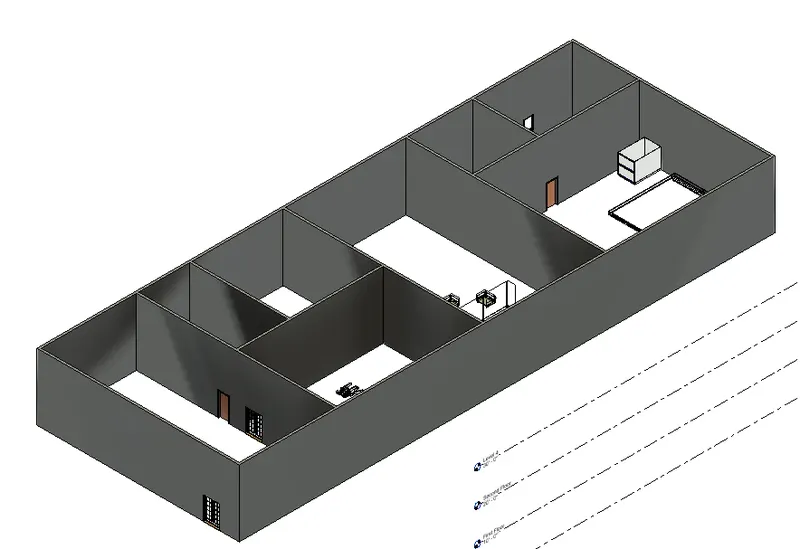
- The images are shown below in different angles.