Creating Levels, Grids, Layout and model elements for a residential unit using REVIT
Revit Challenge 2
Submitted By Kanala Rahul Reddy
- What is BIM? Summarize the features of BIM and the benefits of using BIM over 2D CAD tools.
A). BIM is an acronym for Building Information Modeling or Building Information Management. It is a highly collaborative process that allows architects, engineers, real estate developers, contractors, manufacturers, and other construction professionals to plan, design, and construct a structure or building within one 3D model.
Levels in BIM
Different levels of BIM can be achieved for various types of projects. Each level represents a different set of criteria that demonstrates a particular level of ‘maturity.’ BIM levels start with 0 and go to 4D, 5D, and even 6D BIM. The purpose of these levels is to gauge how effectively, or how much information is being shared and managed throughout the entire process.
- Level 0 BIM: Paper-based drawings + zero collaboration
- Level 1 BIM: 2D construction drawings + some 3D modeling
- Level 2 BIM: Teams work in their own 3D models
- Level 3 BIM: Teams work with a shared 3D model
- Levels 4, 5, and 6 BIM: Adding in scheduling, cost, & sustainability information
Difference between 2D CAD and BIM
Basically, when using CAD for building design, you focus on creating drawings. When using BIM, you focus on creating a building model, and then the drawings can be generated from the model. This saves time because you really do not have to draw anything twice. With CAD, you typically draw floor plans and then sections. But with BIM, you create the elements in one view, and they appear in all views in which their visibility is turned on.
Additionally, when it comes to documenting your design with tags and schedules, the parameters that are programmed into the elements can easily be used. This saves time when it comes to updating building components, and it cuts down on errors since a component will not be tagged differently in two views
2) Understand the concept of Categories, Families, Elements, Instances in Revit. Go to Insert Tab, choose a category. Pick a family and element. Understand the instances and insert them into the Revit model
Category: A Category controls the organization, visibility, graphical representations, and scheduling options of Families within the Project.
Family: A Family is a grouping of 2D and/or 3D information that serves to represent a discrete building or documentation element in the Project. It defines parametric, graphical, and documentation requirements.
There are three kinds of Revit Families
- System: These are the families that are pre-defined families specific to a Revit Project. Their parametric, graphical, and documentation requirements already exist. They can not be created in, deleted from, loaded into, or saved out of the current project.
- Loadable: These are the families that are user-defined families built in an editing mode called the Family Editor using family templates. Their parametric, graphical, and documentation requirements can be defined from scratch. They can be created and loaded into a project as well as, deleted or saved from a project.
- In-Place: These are the families that are user-defined families created to represent a one-of-a-kind element unique to the project. Like System families they cannot be loaded into or saved out of a project but, they can be created within the context of the project using familiar Family Editor tools.
Type: A Type is a specific representation in a Family defined by distinct parametric, graphical, and documentation characteristics which makes it unique from other Types in the Family.
Instance: An Instance is an individual representation of a Type in the Project defined by unique parametric, graphical, and documentation characteristics which makes it unique from other Instances in the Project.
Aim: To create a family in Revit
Step 1: Go to Insert Tab as shown below and click on “Load Family”
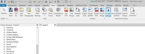
Step 2: Add Family
From the pop-up box select libraries
Select English-Imperial / Structure Precast / Custom Slab as shown in the figure below
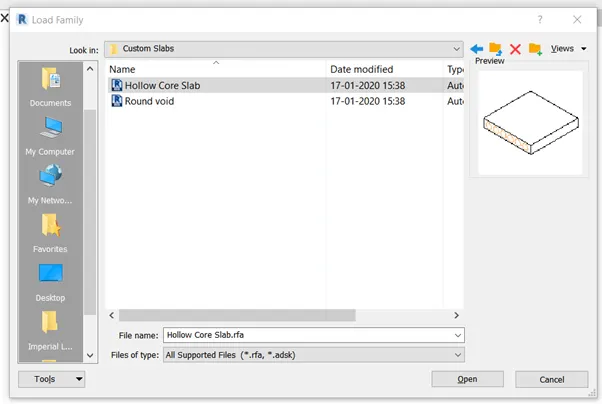
- Click on hollow core slab and click OK
Step 3: Project browser
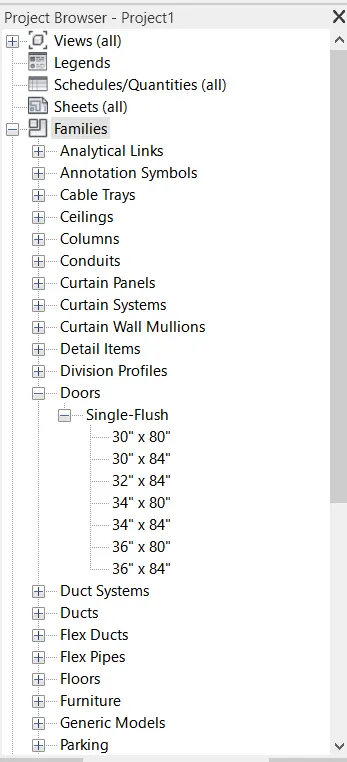
Families can also be added from the project browser as follows
3) Setting up a Project – Open a project file with an architectural template. Save the file with an appropriate name. Set up the project units to Imperial / Metric based on your convenience of modeling. Complete the project information under the Manage tab. Set up the maximum backups for project file to 3
A). AIM: To Set up a project
Procedure:
Step 1: Open REVIT
Click the windows button and type REVIT and press enter
- Once the REVIT is open, the home page is as follows
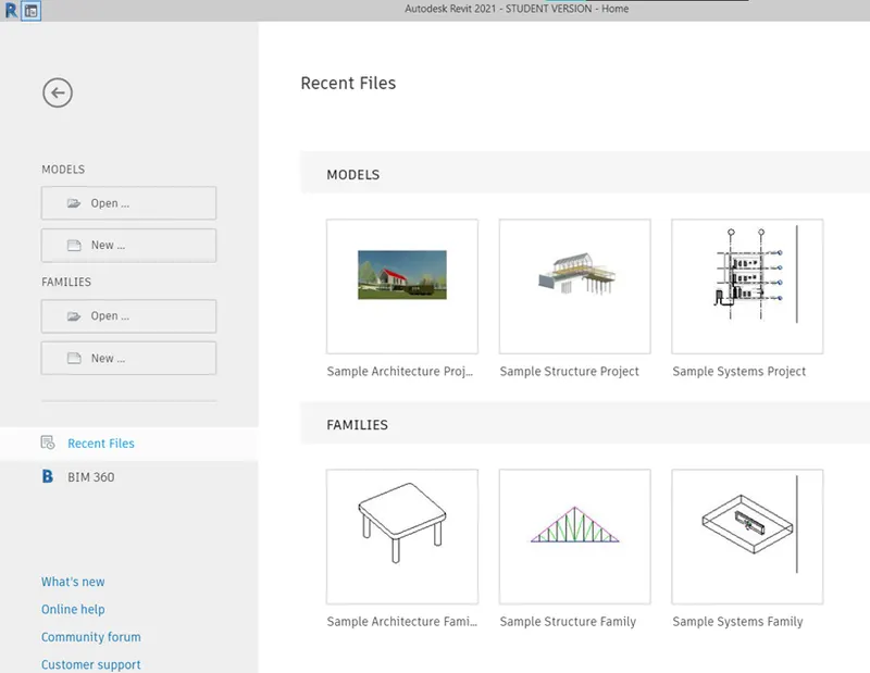
Step 2: Creating Architectural Template and Saving Template
Click on New from the home page
- In the dialogue box click on Metric- Architectural template
- Click on create new “project”.
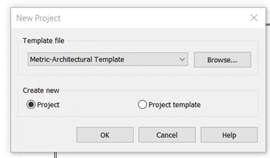
- Click OK to open the Architectural template
- Click on the Save button to open the dialogue box to set filename
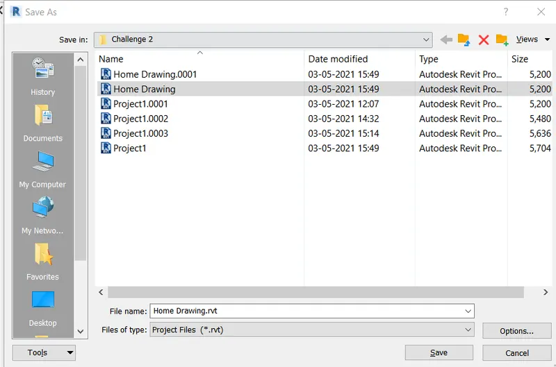
Step 3: Project settings
Go to the Manage tab
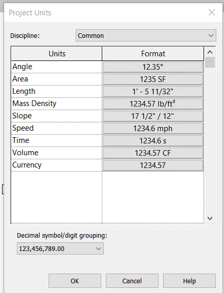
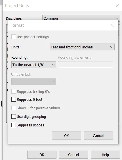
- Click on “Project Units”
- A dialogue box of project units opens
- Units are changed accordingly
Step 4: Project settings
Go to the Manage tab
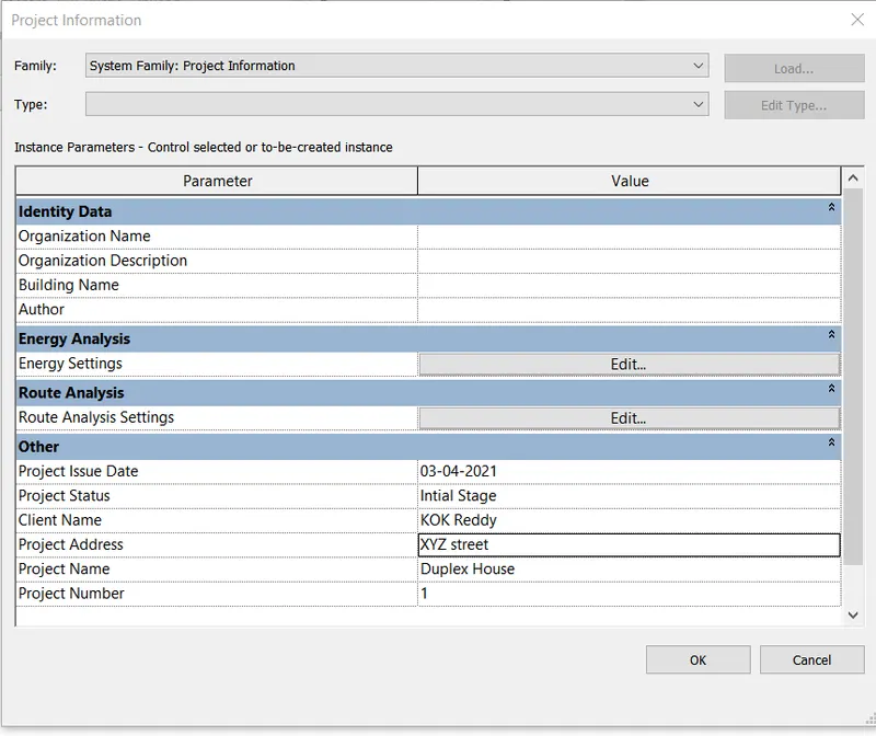
- Click on “Project Information”
- A dialogue box of project information opens
- Details of project information are entered as per convenience
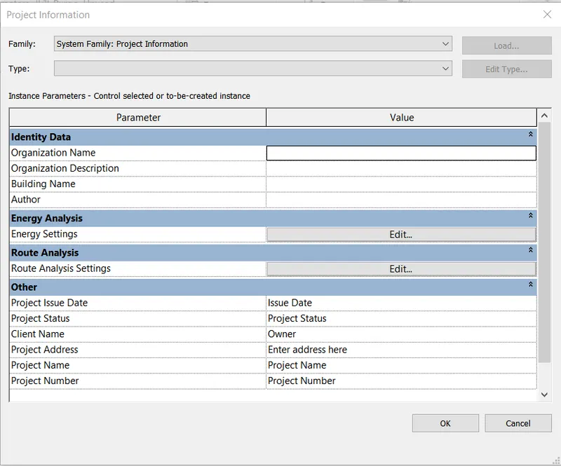
- The end is shown in the result
Result:
Initially the project is saved with an appropriate name. The result after entering the project units and project information such as Project name, Project Issue Date, Project status, Project Number.
Project Units
Project Information
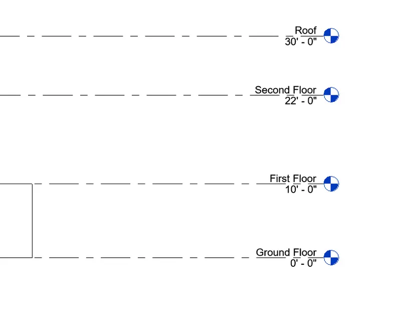
4) Understand the concept of Levels and Grids. Follow the naming and conventions. Create the following Levels: (Convert to metric equivalents if the metric is your units)
Ground Floor @ 0’
First Floor @ 10’
Second Floor @ 20’
Roof @ 30’
Grids Transverse Grids A, B,C, D, E @ 10’ spacing
Longitudinal Grids from 1 to 10 @ 20’ spacing
A). AIM: To create levels and grids for standard layout
Procedure:
Step 1: Open REVIT
Click the windows button and type REVIT and press enter
- Once the REVIT is open, the home page is as follows
Step 2: Create an Template
Create a new construction template as shown below
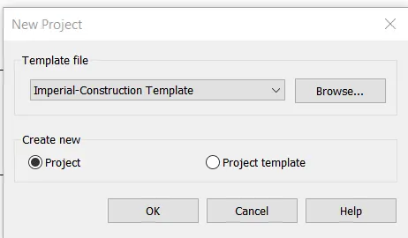
Step 3: Project Information
Enter all the project information and project units necessary
Step 4: Create Layout
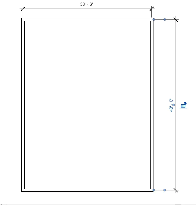
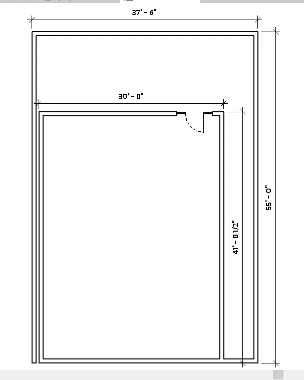
Create a layout of 30'6"X40'6" as shown in figure
Step 4: Viewing Levels
Go to elevation view such as east/north/west/ south
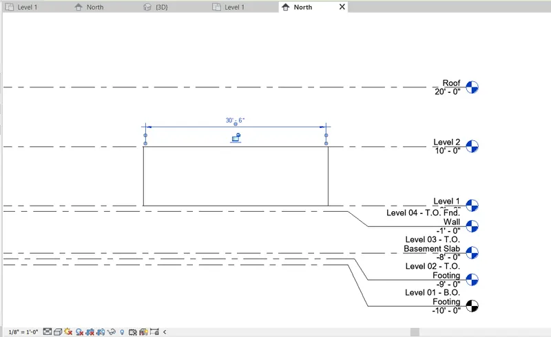
To create specific levels Go to architectural tab and click on level to add
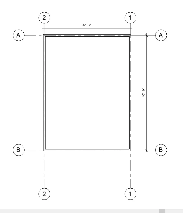
Step 5: Creating Grids for the outer layout
Go to Construction Tab and and click on "Grid"
- Create Horizontal grids as alphabets A,B
- Create Vertical grids as Numbers 1&2
Result:
The Levels and grids are created as required.
Grids Transverse Grids A, B,C, D, E @ 10’ spacing
Longitudinal Grids from 1 to 10 @ 20’ spacing
5) 3D modeling of the residential unit – From looking at your house / or a place you aspire. Create a conceptual layout of the residential unit. You can measure using tape or you can access your residential plan to create a similar layout.
A). AIM: To create 3D modeling of the residential unit
Procedure:
Step 1: Open REVIT
Click the windows button and type REVIT and press enter
- Once the REVIT is open, the home page is as follows
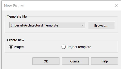
Step 2: Create a Template
Create a new Architectural Template as shown below
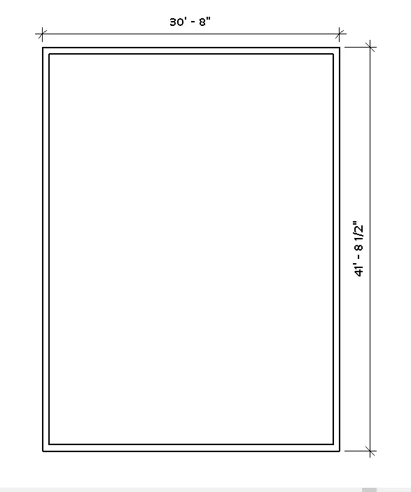
Step 3: Creating Layout
Create a rectangular layout of 30'8"X 41'8.5" as shown in the figure
6) In the layout created draft the level of details you are planning to include – Dimensions of room, components you plan to add in the residential unit.
Contd. from the previous question
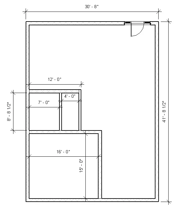
Step 4: Drawing Rooms and components
One Master bedroom with toilet, Living room, Kitchen and Toilet are drawn as shown in the following figure
Dimensions of respective are also shown in the figure
7) Identify the residential model elements such as Door, Windows, Tables, Chairs, Couch, Bed, Lamps from the library and insert them into the model. Save the project for use
for Assignment 3
Contd. from the previous question
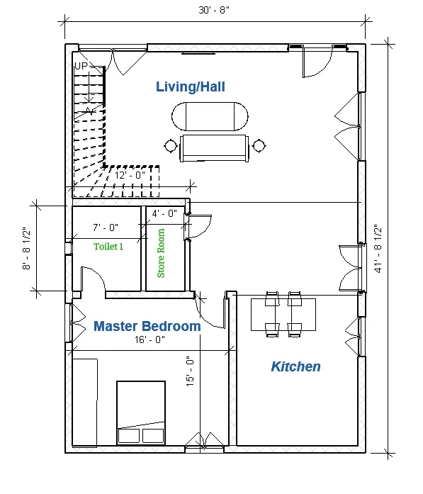
Step 5: Drawing components
Components such as Door, Windows, Tables, Couch, Bed, Telivision, Dining Table, Staircase to second Floor
Go to Insert Tab and click on load families
- From the popup, click on 'Libraries'
- Select the component from various options given by revit models
- Place the component at its respective location with its specific dimensions
Result:
This result is for 5,6,7 questions combined
The total layout, including plot details and plinth area with main entrance door is shown below
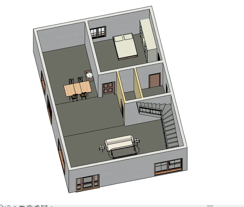
3D view of the Ground Floor Plan with basic components mentioned above