Creating Levels, Grids, Layout and model elements for a residential unit using REVIT
1) What is BIM? Summarize the features of BIM and benefits of using BIM over 2D CAD tools.
BIM (Building Information Modelling) is the design and documentation system that supports the design drawings and shedules reuired for the building project.It helps to stimulate the construcion and visualize the structure.
Features of BIM-
- Easy access to information.
- Making the process more expressive.
- Comprehensive view of the project.
Benefits of using BIM
- it works in 5D ie length, breath, height, cost and time.
- We get complete representation of bulding design.
- Insatant Updates of all the components.
- Time constraint.
- Resource tracking.
2) Understand the concept of Categories, Families, Elements, Instances in Revit. Go to Insert Tab, choose a category. Pick a family and element. Understand the instances and insert it to Revit model
- Category- It controls the organization,visibility graphical representaions and scheduling of families within the project.
- Family- A family is group of 3D or 2D information that serves to represent a discreate building or documentation element in the project.
- Type- It is a specific representaion in a family defined by disticnt pramatrical and documentationof building.
- Instances- It is an individaul representation of a type in the project defined by unique prametric
AIM- TO PIVK AND INSRET A FAMILY AND INSTANCES OR ELKEMENT
PROCEDURE-
OPEN REVIT SOFTWARE
CLICK ON NEW
CREATE TEMPLATE FILE AS ARCHITECTURAL TEMPLATE
CREATE NEW AS PROJECT AND THEN CLICK OK
THEN CLICK ON PROJECT BROWSER
AFTER THAT CLICK ON PROJECT BROWSER THEN CLICK ON DOORS
SELECT THE DOOR REQUIRED AND DRAW IT ON THE SCREEN DRAWING OF WALLS
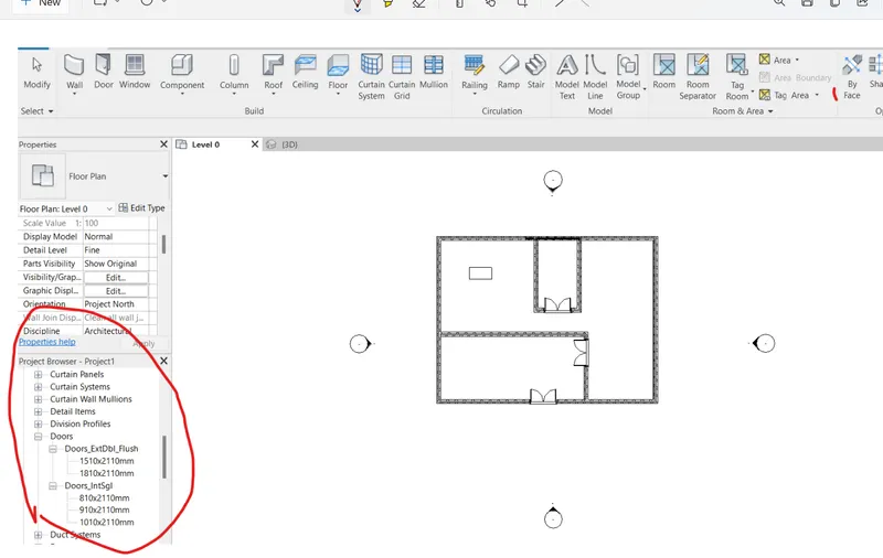
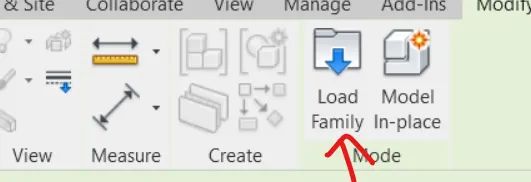
ALSO WE CAN DO THIS BY GOING ON ARCHITECTURE TAB THEN CLICK ON COMPONENT THEN WE GET THE OPTION OF LOAD FAMILY
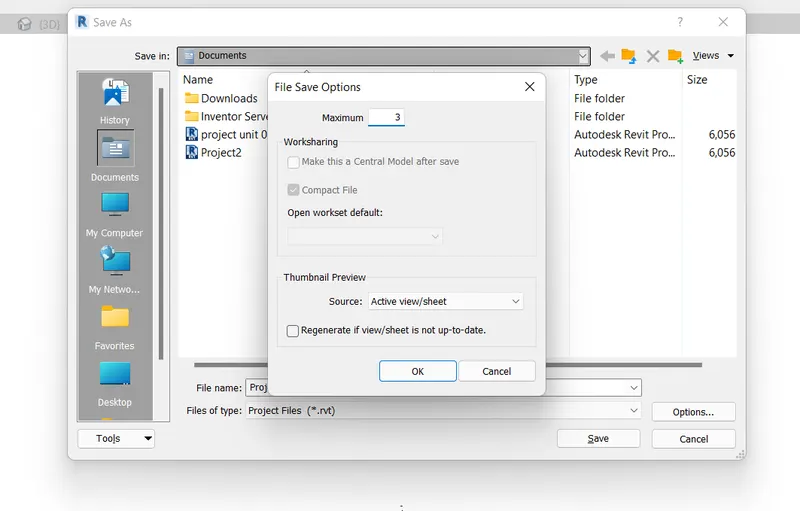
3) Setting up a Project – Open a project file with architectural template. Save the file with appropriate name. Set up the project units to Imperial / Metric based on your convenience of modelling. Complete the project information under Manage tab. Set up the maximum backups for project file to 3
AIM- TO SET UP THE PROJECT
PROCEDURE-
OPEN REVIT SOFTWARE
CLICK ON NEW
CREATE TEMPLATE FILE AS ARCHITECTURAL TEMPLATE
CREATE NEW AS PROJECT AND THEN CLICK OK
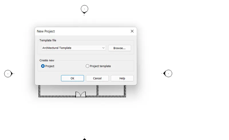
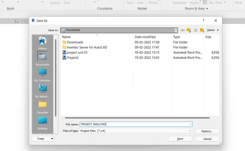
SAVE THE FILE WITH NAME PROJECT SKILLLYNC
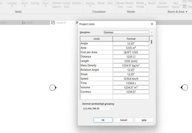
TYPE UN AND SELECT THE UNITS
CLICK ON MANAGE THEN CLICK ON PROJECT INFORMATION
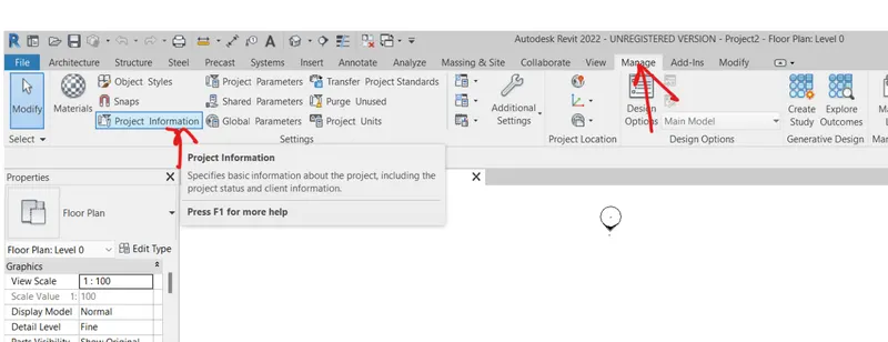
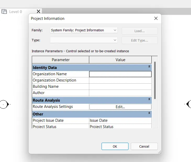
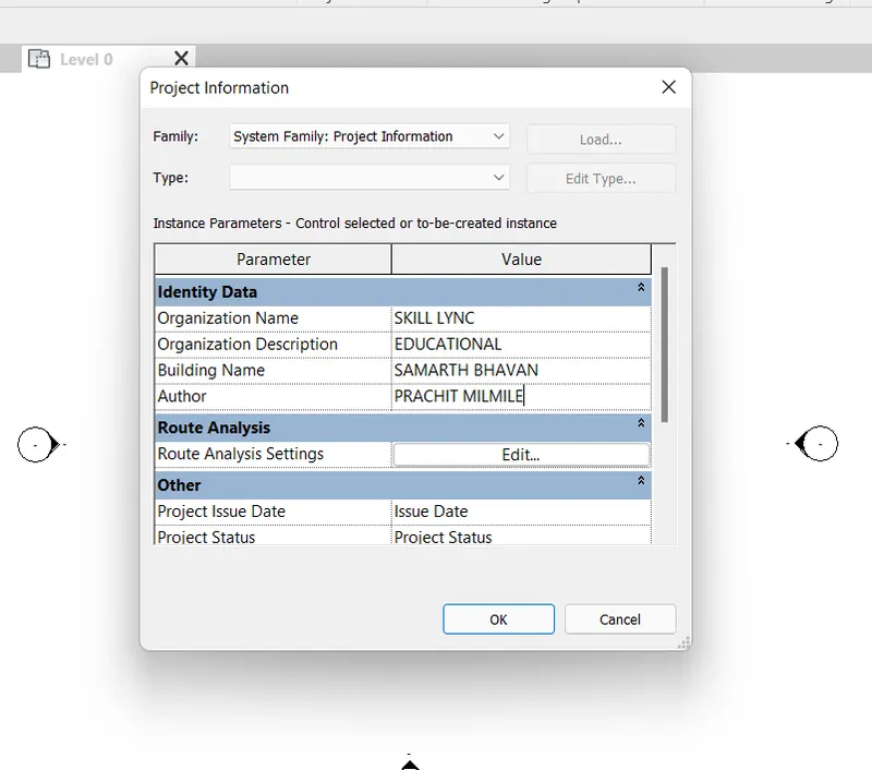
CLICK ON SAVE AND THEN CLICK ON OPTIONS AND CREATE 3 BACKUPS
4) Understand the concept of Levels and Grids. Follow the naming and conventions. Create the following Levels: ( Convert to metric equivalents if metric is your units)
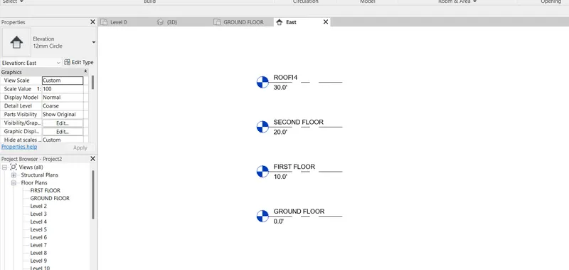
Ground Floor @ 0’
First Floor @ 10’
Second Floor @ 20’
Roof @ 30’
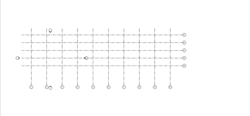
Grids Transverse Grids A, B,C,D, E @ 10’ spacing
Longitudinal Grids from 1 to 10 @ 20’ spacing
AIM- TO DRAW GRIDS AND LEVELS
INFORMATION -
Ground Floor @ 0’
First Floor @ 10’
Second Floor @ 20’
Roof @ 30’
Grids Transverse Grids A, B,C,D, E @ 10’ spacing
Longitudinal Grids from 1 to 10 @ 20’ spacing
PROCEDURE-
OPEN REVIT SOFTWARE
CLICK ON NEW
CREATE TEMPLATE FILE AS ARCHITECTURAL TEMPLATE
CREATE NEW AS PROJECT AND THEN CLICK OK
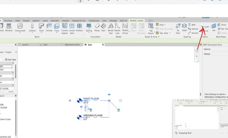
THE LEVELS CAN ONLY BE CREATED FROM ELEVATIONS
GO TO PROJECT BRWOSER CLICK ON ELEVATIONS
2 LEVELS ARE ALREADY CREATED RENAME THEM TO GROUND FLOOR AND FIRST FLOOR
NOW TO CREATE GRIDS
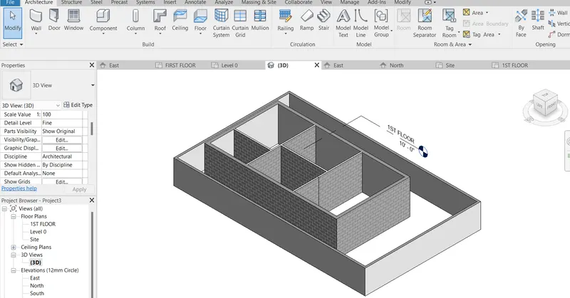
5) 3D modelling of residential unit – From looking at your house / or a place you aspire. Create a conceptual layout of the residential unit. You can measure using a tape or
you can access your residential plan to create a similar layout.
AIM- TO DRAW A 3D RESIDENTIAL MODEL
INFORMATION-
PLOT IS OF 33'X 55'
PROCEDURE-
OPEN REVIT SOFTWARE
CLICK ON NEW
CREATE TEMPLATE FILE AS ARCHITECTURAL TEMPLATE
CREATE NEW AS PROJECT AND THEN CLICK OK
THE LEVELS CAN ONLY BE CREATED FROM ELEVATIONS
GO TO PROJECT BRWOSER CLICK ON ELEVATIONS
RENAME LEVELS TO GROUND FLOOR AND ROOF
CLICK ON WALL EDIT THE WALL TO 6" FOR THE COMPOUND WALL EDIT THE WALL AND HEIGHT IS 7"
CLICK ON WALL EDIT CREATE DUPLICATE CREATE 9" WALL DRAW THE OUTER WALL HEIGHT OF WALL IS 10'
CREATE A INNER WALL BY SAME PROCESS OF 4.5" HEIGHT OF WALL IS 10'
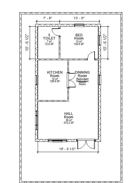
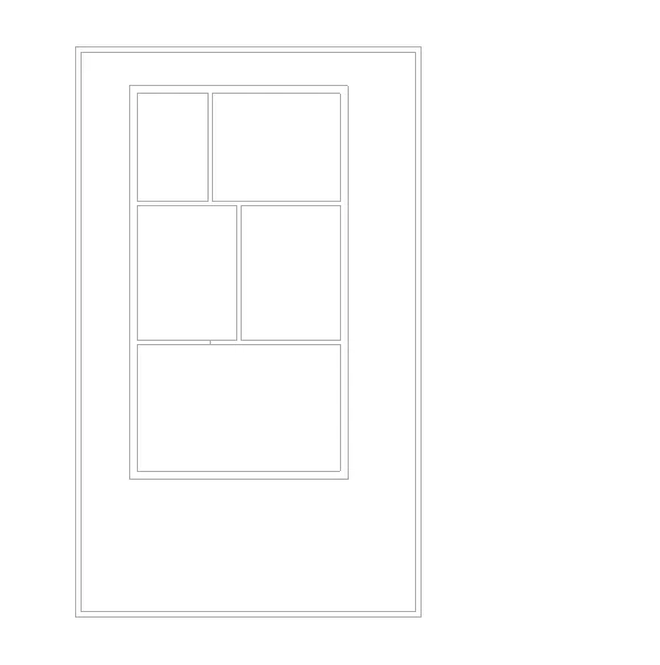
THE LAYOUT IS DRWAN
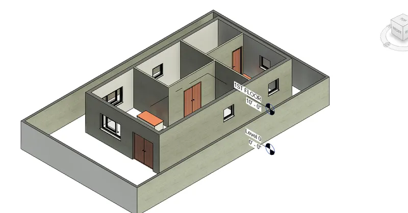
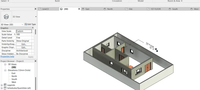
CLICK ON 3D VIEW FOR 3D MODEL
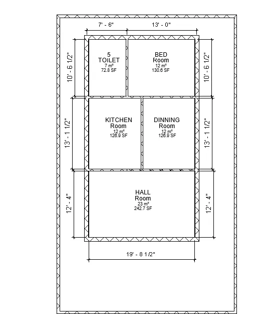
6) In the layout created draft the level of details you are planning to include – Dimensions of room, components you plan to add in the residential unit.
TAG THE ROOM
AND THEN REANME THE ROOM AS IT SHOULD BE
HALL DINNING AND KITCHEN
DIMENTION OF THE ROOSMS ARE GIVEN BY CLICKING ON ANNOTATE AND THEN
CLICK ON ALINGED DIMENTIONS TAKE INNER TO UNNER WALL DIMENSTIONS
7) Identify the residential model elements such as Door, Windows, Tables, Chair, Couch, Bed, Lamps from the library and insert them to the model . Save the project for usefor Assignment 3
CLICK ON DOORS SLECT THE REQUIRED DOORS ON ARCHITECTURSL TAB PLACE WHERE REQUIRED
SLECT THE WINDOWS ON ARCHITECTURSL TAB PLACE THE WINDOWS WHERE REQUIRED