Creating Kitchen layout, Hatching of Architectural elements and sectional view of an Industrial Building in AutoCad
AIM:
To create a Kitchen layout, Hatching of Architectural elements and sectional view of an Industrial Building in AutoCad
INTRODUCTION:
The main objective of doing this project is to understand in detail about the various options and tools which are used for hatching. The various tools which are used for doing this project Line, Rectangle, Construction Line, Polygon, circle, eraze, copy, trim, Layer, Mirror, Copy, Offset, Extend, Move, Rotate, Text, Fillet etc.
Line: The line object is the most basic and common object in AutoCAD drawings of any discipline. Each segment is a line object that can be edited separately, assigning properties such as layer, line type, and line weight.
Construction Lines: Construction lines (also known as xlines) are temporary line work entities that can be used as references when creating and positioning other objects or line work. Construction lines are either circles or straight lines that extend to infinity in both directions
Polygon: Creates an equilateral closed polyline. We can specify the number of sides of the polygon and whether it is inscribed or circumscribed.
Rectangle: When using the RECTANGLE command, absolute or relative coordinate values are used to define the size of the rectangle. Actual dimension values are preferred to create the length and width of the rectangle. Command used- REC
Circle: Created a circle Command used - CIRCLE or C
Erase: The erase command is used to remove or delete objects from the drawing. The selected objects can also be removed with the help of the 'Delete' button on the keyboard. We can also delete faces, vertices, and meshes in 3D with the help of Erase command.
Copy: Copies objects a specified distance in a specified direction. With the COPYMODE system variable, you can control whether multiple copies are created automatically.
Trim: Trims objects to meet the edges of other objects. Command used: TR
Layers: Use layers to control the visibility of objects and to assign properties such as colour and line type. Objects on a layer normally assume the properties of that layer. However, you can override any layer property of an object. For example, if an object’s colour property is set to BYLAYER, the object displays the colour of that layer. If the object’s colour is set to Red, the object displays as red, regardless of the colour assigned to that layer. Command used- LAYER
Mirror: The mirror command in AutoCAD is used to create a copy (mirror copy) of the selected object. We can also delete the source object after mirroring the object. The objects that represent the same as the half of their object can be mirrored across a center line to create the other half of the object.
Offset: Creates concentric circles, parallel lines, and parallel curves. Command used: OFFSET.
Extend: Extends objects to meet the edges of other objects. To extend objects, first select the boundaries. Then press Enter and select the objects that you want to extend. To use all objects as boundaries, press Enter at the first Select Objects prompt. Command used: EX
Move: The move command in AutoCAD is used to move objects at a specified distance and direction.
To move the objects with precision, we can use object snaps, grid snaps, coordinates, etc.
Rotate: Used to rotate objects in our drawing around a specified base point. To determine the angle of rotation, we can enter an angle value, drag using the cursor, or specify a reference angle to align to an absolute angle. Command used: ROTATE
Dimension: Creates multiple dimensions and types of dimensions with a single command. We can select objects or points on objects to dimension, and then click to place the dimension line. When we hover over an object, the DIM command automatically generates a preview of a suitable dimension type to use.
Text: We can use single-line text to create one or more lines of text, where each text line is an independent object that you can move, format, or otherwise modify. Right-click in the text box to select options on the shortcut menu.
Fillet: The fillet tool helps form round corners between any two entities that form a sharp vertex. Command used: FILLET
HATCH: The Hatch command in AutoCAD is used to fill patterns inside an enclosed area. The patterns are hatched, gradient, and solid fill. The gradient patterns are defined as a smooth transition between two colors. There are several hatch patterns available in AutoCAD. We can choose the desired pattern from the list of the patterns according to the requirements. The number of hatch lines represented in any pattern can be adjusted with the help of the Hatch Pattern Scale.
TASK 1:
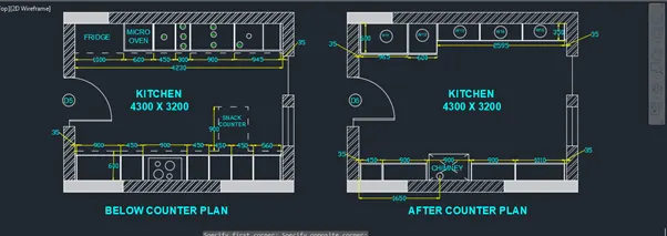
To create the layouts of the Kitchen and provide hatches pattern as shown. Also, use blocks wherever required. Provide appropriate dimensions in the plan. Assume the size of doors, appliances and others as per the standards.
- Click on AutoCAD application and open this application
- Type QNEW in command bar and enter
- Select default setting as Metric
- In default setting click on use a wizard and in that advance setting and set unit as decimal and precision as 0 and press Next
- Set Angle as Decimal Degree and precision as 0 and click next
- Set Angle Measure as EAST and press NEXT
- Set Angle Direction as Counter-Clockwise and press NEXT
- Set Area by providing Length as 100 and Width as 100
- Press finish
- Keep ortho, Object snap >ON
- Keep Snap and Grid > Off
- Un+enter
- Type > Decimal, Precision > 0
- Units to scale inserted content > milimeter
- Enter
- Below Counter Plan :
- Take xline command
- Put xline horizontal and xline vertical
- Trim the negative coordinates
- Take offset of both lines at 230mm distance
- Take offset command
- Select distance as 4230 and select object as vertical inner wall line
- Again take offset command
- Offset the last object at a distance of 230
- Trim the unwanted lines
- Take offset command
- offset distance > 3200
- Select object > Click on Horizontal line
- Again take the offset to last object at 230
- Trim the unwanted lines
- From Properties tab
- Click on drop down
- Other > Load
- Select ACAD_ISO02W100 > OK
- Set Global Scale Factor as 10
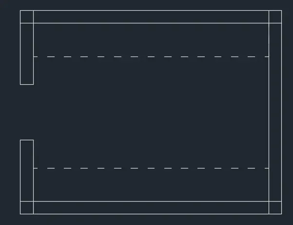
- Provide the dotted line at 600 distance as shown below
- Assume the door size as 1000
- Leave the space for door as shown below
- Take offset command
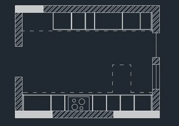
- Offset the Short vertical wall at a distance of 35, 935, 1385, 2285, 2735, 3185, 3635, 4195 as shown below
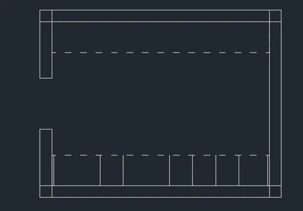
- Assume the thickness as 12
- Take offset command and provide the thickness as given below
- Use the line command in Hob section
- Use the circle command in hob
- Take line command
- Provide the snack counter using dotted line as shown below
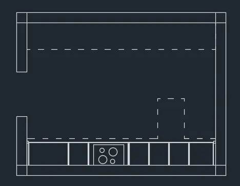
- Now to create offsets for fridge, microwave and all
- Offset the Short vertical wall at a distance of 1000, 1600, 2050, 2350, 3250, 4195 as shown below
- Take a dotted line
- Provide it at a height of 600 from upper horizontal line
- Trim the projection lines
- Assume the thickness as 12
- Take offset command and provide the thickness as given below
- Assume the size of Window as 800 and door near that window size is 800
- From the draw panel
- Click on hatch
- Select ANSI32 hatching
- Select the area where to provide that hatch
- Enter
- Take properties of hatching system
- Take scale as 300
- From the draw panel
- Click on hatch
- Select Solid hatching
- Select the area where to provide that hatch
- Enter
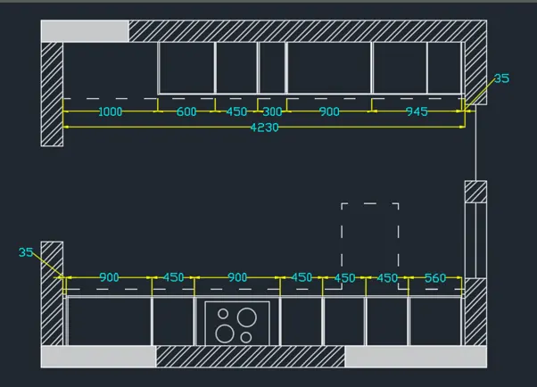
- Click on Annotation
- Manage dimension style
- Modify dimension style
- Select arrow size > 50
- Arrow, Dimension line and extension line colour > Yellow
- Text size > 80
- Text colour > Cyan
- Enter
- Take linear dimension command
- Provide it to show the 35mm dimension
- Then use contibuous dimension Command
- Provide the dimensions
- To opposite side repeat the procedure
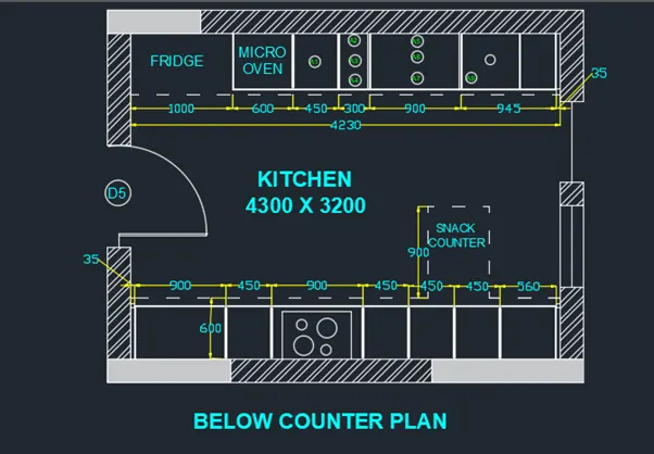
- To create the text
- Click on Annotation tab > Multi-line
- Manage textile > New
- Style name as > NEW > OK
- Font Name > Arial
- Font Style > Bold
- Height > 150
- And press set current
- Use Multiline text
- And fill the required text as Kitchen
- To create the text
- Click on Annotation tab > Multi-line
- Manage textile > New
- Style name as > Other > OK
- Font Name > Arial
- Font Style > Regular
- Height > 150
- And press set current
- Use Multiline text
- And fill the required text as shown below
- Use circle command to show the synk hole
- Use the line command, Circle command to show the door as shown below
- Above Counter Plan
- Take construction line command
- Take offset of both lines at 230mm distance
- Take offset command
- Select distance as 4230 and select object as vertical inner wall line
- Again take offset command
- Offset the last object at a distance of 230
- Trim the unwanted lines
- Take offset command
- offset distance > 3200
- Select object > Click on Horizontal line
- Again take the offset to last object at 230
- Trim the unwanted lines
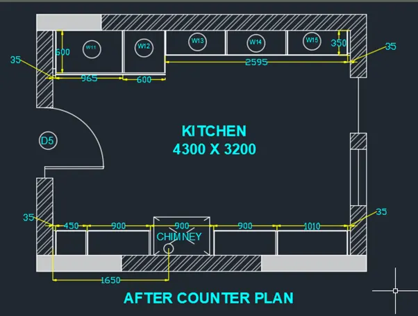
- Provide the offset at 350mm
- Assume the door size as 1000
- Leave the space for door as shown below
- Take offset command
- Offset the Short vertical wall at a distance of 35, 965, shown below
- Assume the thickness as 12
- Take offset command and provide the thickness as given below
- Use the circle command in chimney to show the exhaust pipe
- Assume the size of Window as 800 and door near that window size is 800
- From the draw panel
- Click on hatch
- Select ANSI32 hatching
- Select the area where to provide that hatch
- Enter
- Take properties of hatching system
- Take scale as 300
- From the draw panel
- Click on hatch
- Select Solid hatching
- Select the area where to provide that hatch
- Enter
- Click on Annotation
- Manage dimension style
- Modify dimension style
- Select arrow size > 50
- Arrow, Dimension line and extension line colour > Yellow
- Text size > 80
- Text colour > Cyan
- Enter
- Take linear dimension command
- Provide it to show the 35mm dimension
- Then use continuous dimension Command
- Provide the dimensions
- To opposite side repeat the procedure
- To create the text
- Click on Annotation tab > Multi-line
- Manage textile > New
- Style name as > NEW > OK
- Font Name > Arial
- Font Style > Bold
- Height > 150
- And press set current
- Use Multiline text
- And fill the required text as Kitchen
- To create the text
- Click on Annotation tab > Multi-line
- Manage textile > New
- Style name as > Other > OK
- Font Name > Arial
- Font Style > Regular
- Height > 150
- And press set current
- Use Multiline text
- And fill the required text as shown below
- Use circle command to show the synk hole
- Use the line command, Circle command to show the door as shown below
- Result :-
PROBLEM 2
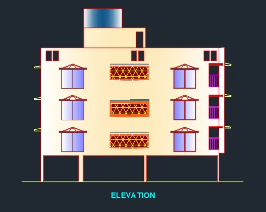
- Aim :- To create the elevation of the plan created in challenge 7 and apply hatch in the walls, doors and windows and other architectural elements.
- Introduction :-
The general commands used for drawing the building is as follows :
- Line
- Polygon
- Rectangle
- Circle
- Erase
- Copy
- Trim
- Mirror
- Offset
- Extend
- Array
- Move
- Rotate
- Dimension
- Text
- Fillet
Etc
- Procedure :-
- Click on AutoCAD application and open this application
- Type QNEW in command bar and enter
- Select default setting as Metric
- In default setting click on use a wizard and in that advance setting and set unit as decimal and precision as 0 and press Next
- Set Angle as Decimal Degree and precision as 0 and click next
- Set Angle Measure as EAST and press NEXT
- Set Angle Direction as Counter-Clockwise and press NEXT
- Set Area by providing Length as 50 and Width as 50
- Press finish
- Keep ortho, Object snap >ON
- Keep Snap and Grid > Off
- Un+enter
- Type > Decimal, Precision > 0
- Units to scale inserted content > milimeter
- Enter
- To draw the elevation, the Plan of challenge 7 is reffered
- Take the xline command
- Select > Vertical
- Specify the points required to take projection for Elevation
- Take the perpendicular line
- Enter
- Take the offset command and provide it at required places
- Use the line command to show the handgrills for balconr
- Use the line command to show the chajjas
- Use rectangle command to show the design to the parapet
- To create the hatching
- From draw panel, click on > Hatch
- Select the hatch type
- Scele it
- And provide it at required places
- To provide the hatching to windows and ventilators, I used the gradient style, which shows the following results
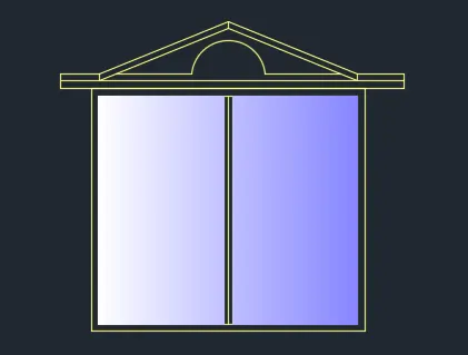
- Similarly by this way, I provided hatching to doors and other units also
- It will shows the following result
- Result :-
PROBLEM 3
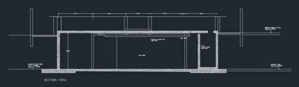
- Aim :- To Create the sectional view of an industrial building by Providing appropriate hatches, dimensions and annotations to the drawing.
- Introduction :-
The general commands used for drawing the building is as follows :
- Line
- Polygon
- Rectangle
- Circle
- Erase
- Copy
- Trim
- Mirror
- Offset
- Extend
- Array
- Move
- Rotate
- Dimension
- Text
- Fillet
Etc.
- Procedure :-
- Click on AutoCAD application and open this application
- Type QNEW in command bar and enter
- Select default setting as Metric
- In default setting click on use a wizard and in that advance setting and set unit as decimal and precision as 0 and press Next
- Set Angle as Decimal Degree and precision as 0 and click next
- Set Angle Measure as EAST and press NEXT
- Set Angle Direction as Counter-Clockwise and press NEXT
- Set Area by providing Length as 100 and Width as 100
- Press finish
- Keep ortho, Object snap >ON
- Keep Snap and Grid > Off
- Un+enter
- Type > Decimal, Precision > 0
- Units to scale inserted content > milimeter
- Enter
- Take a line command
- Specify first point > anywhere in the drawing
- Specify next point as > 30000 approximately > enter by keeping the curser to the right side
- Specify next point as > 5550 approximately > enter by keeping the curser to the up side
- Specify next point as > 30000 approximately > enter by keeping the curser to the left side
- Specify next point as > 5550 approximately > enter by keeping the curser to the down side
- It will create the following result
- Use the line command and offset command to show the components which are shown in drawing
- To create the text
- Click on Annotation tab >multi line
- Manage textile > New
- Style name as > Challenge > OK
- Height > 200
- And press set current
- Use multiline text
- And fill the required text in drawing as shown below
- Set current layer to dimension layer
- Click on ANNOTATION tab
- Click on Dimension
- Click > Manage dimension style
- Style name > Challange
- Set the characteristics of dimensions as
- Select arrowhead size as 150
- Select Text Style > Challange
- Text Height > 150
- Then select linear dimensions
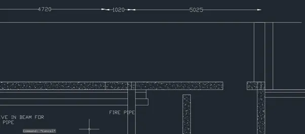
- provide the dimensions wherever necessary
- To create the Leader
- Click on Annotation tab >Multileader
- Manage leader style > Project leader
- Maximum leader points 2
- Size > 100
- Text style > Challange
- Font Name > Arial
- Height > 200
- And press set current
- And fill the required text in drawing as shown below
- It will show us following result
- Result :-