Creating Kitchen layout, Hatching of Architectural elements and sectional view of an Industrial Building in AutoCad
Aim of the project: To create layout of the drawings created a few weeks in the challenges.
Procedure:
Step 1: The layout as per mentioned is selected i.e., Tutorial.mArch.dwt from the templates existing
Step 2: The view ports are created as per the sizes mentioned and the drawing is adjusted in the view port to view the specific drawing.
Step 3: Another view port of the mentioned size is created and the section of the building is set in that viewport as shown in Figure 1
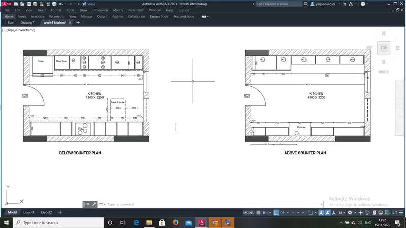
Figure 1
Step 4: For the kitchen drawing the paper size is set to A4 paper size in the layout Page Setup Manager
Step 5: Four different viewports are created of different size to view the required elements of the drawing as shown in the figure 2
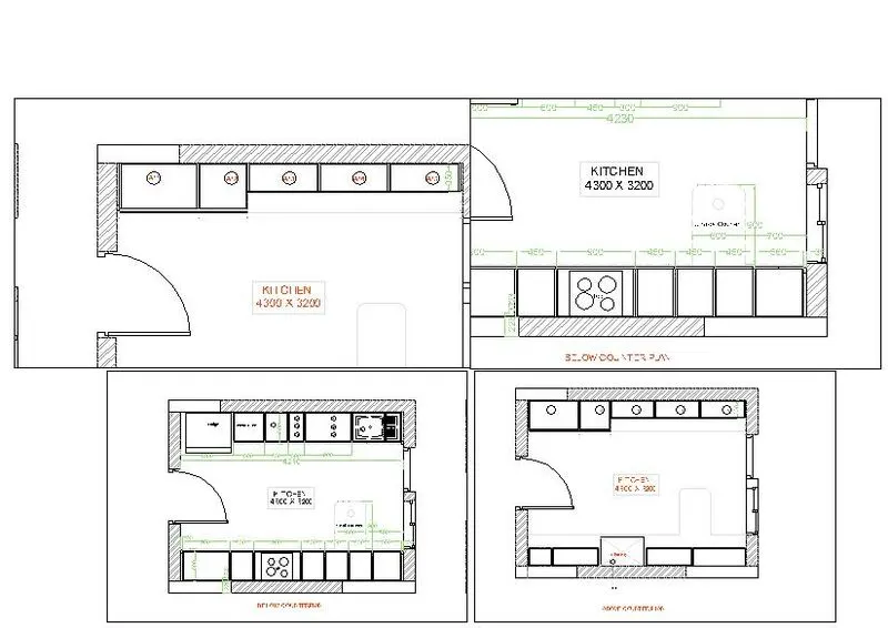
Figure 2
Step 6: To create a layout to view the industrial section drawing, the layout page is setup and 3 different viewports are drawn.
Step 7: The different viewports show different locations of the drawing as shown in figure 3
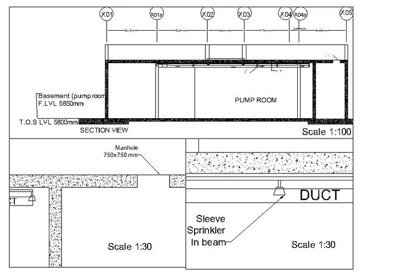
Figure 3
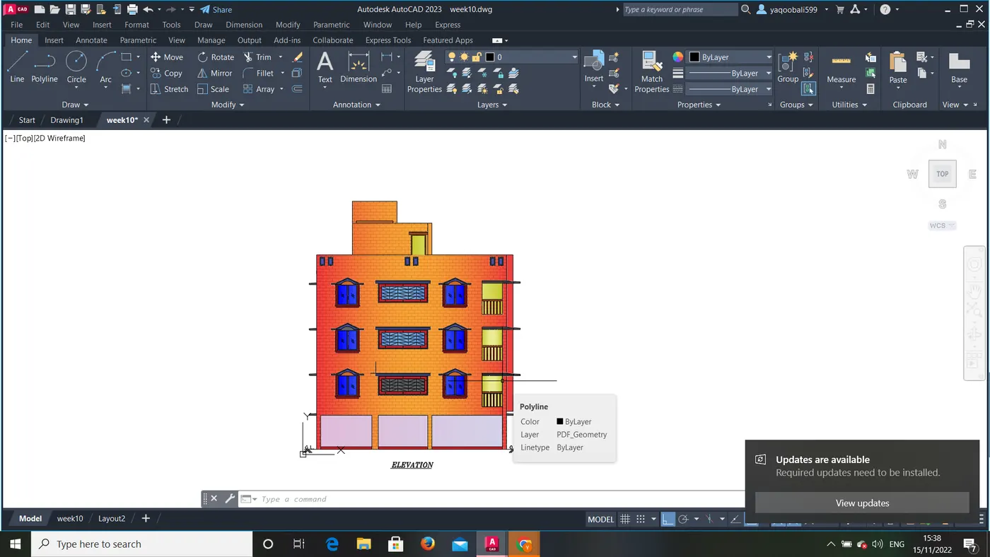
Results Obtained:
The layouts shown here are of various page sizes and set-up. Each of the layout has different viewports of different sizes enabling the viewer to identify the different elements of the drawing.