Creating Kitchen layout, Hatching of Architectural elements and sectional view of an Industrial Building in AutoCad
1.
Aim:
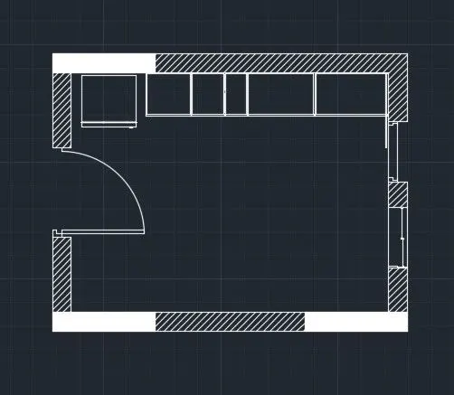
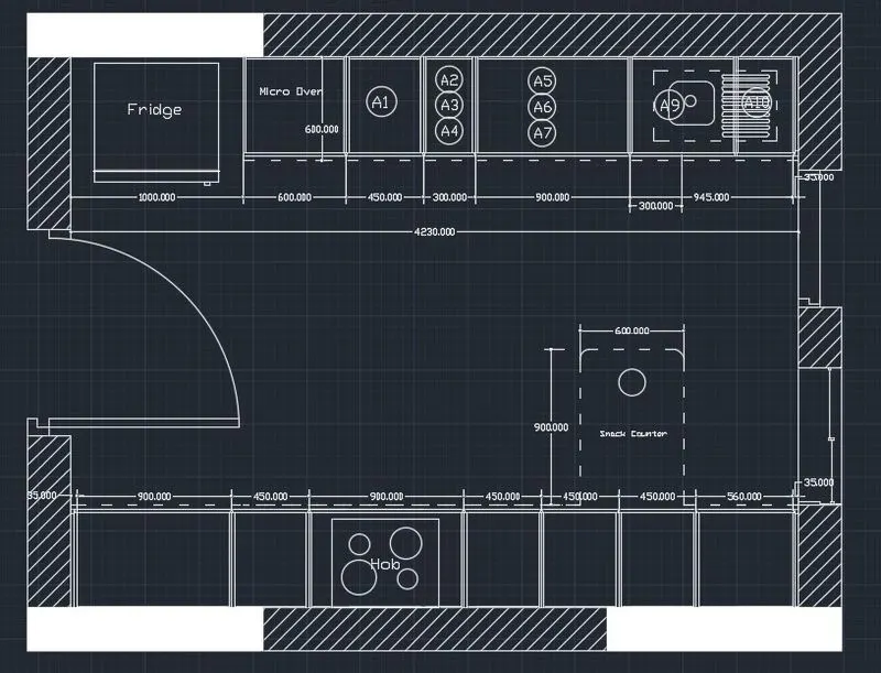
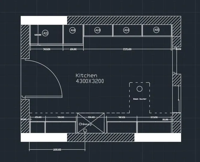
To Create the layouts of the Kitchen and provide hatches pattern using autocad command and tools.
Introduction:
Create the layouts of the Kitchen and provide hatches pattern as shown. Also, use blocks wherever required. Provide appropriate dimensions in the plan. Assume the size of doors, appliances and others as per the standards.
Procedure :-
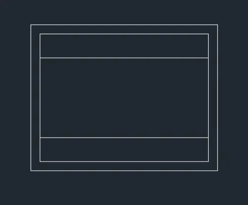
- Type Line command and draw rectangle of size 4700 X 3700.
- Type offset command of size 250 mm inside the rectangle.
- Draw the door using line and arc command.
- Draw the window as per the drawing.
- Type HATCH command in command line.
- Choose the type of hatch you want to use in the drawing.
- Type the scale and click at the object.
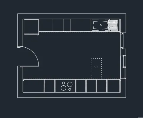
- Then Offset the lines with size of 1000, 600, 450,300, 900, 945, 35 units as per the drawing.
- And make the Platform and Fridge as per the drawing.
- Draw the same platform at the other side.
- Type offset command of size 35, 900, 450, 900, 450, 450, 450, 560, 35 .
- Draw the hob and place the circle in the hob.
- Using dotted line draw snack counter of size 600 X 700.
- Do the Proper dimensionig and placing names as per the drawing.
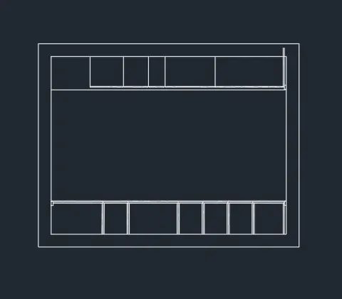
- For above counter plan, use same rectangle box as used before.
- Use line and offset command to make proper platform.
- Draw the same at other side.
- But the sizes are different with compared to below counter plan.
- Annotate proper text and dimensions as per drawing
- Use layer command to show different layers that are used in the drawing.
Result:
Create the layouts of the Kitchen and provide hatches pattern using autocad command and tools is obtained.
2.
Aim:
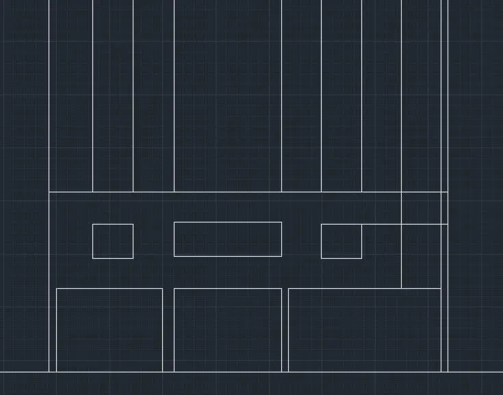
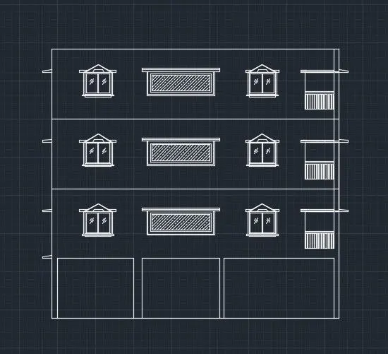
Create the elevation of the plan created and apply proper hatch using autocad command and tools as per plan requires.
Introduction:
Create the elevation of the plan created in the Challenges 7 and apply proper hatch in the walls, doors, windows, and other architectural elements. Refer to the dimensions in Plans and sections in Challenges 7.
Procedure :-
- Use Xline commnad to project the lines in downward direction.
- Project the lines of Columns First.
- Then Project the Lines for window and Balcony.
- Project the lines for levation of verandah(just like Big Balcony).
- Offset 150, 2450, 2850, 2850, 2850 and 1000mm.
- For stairs offset 1250 mm for tread and 150 mm for riser.
- Take 100 mm offset for slab.
- Draw the windows and chhajjas by projectting lines from plan.
- Draw the railings in the balcony by showing column at the corner.
- Give the dimension at suitable places.
- Select the MTEXT command to show the texts in the drawing.
- Project the Chhajjas from the Plan.
- Use the HATCH Command to show hatch in the drawing.
- Draw the Overhead tank above the parapet wall.
- Show the door in the elevation side.
- Draw the text wherever used.
- Use the dimensions wherever used.
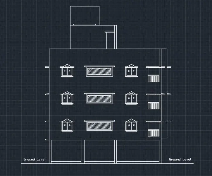
Result:
Create the elevation of the plan created and apply proper hatch using autocad command and tools as per plan requires is done.
3.
Aim:
To Create the section view of an industrial building using autocad command and tools as per drawing requires.
Introduction:
Create the section view of an industrial building as shown in Figure. Provide appropriate hatches and dimensions wherever required. Also, provide annotations to the drawing.
Procedure :-
- Type Line command in command line and draw the lines as per drawing given.
- Height of footing column is 5550 mm and thickness of base footing is 300 mm.
- Draw the ducts below the center column.
- Draw the footing of size 300 mm in depth.
- Draw the footing as per the drawing and set the lineweight.
- Use HATCH Command to fill the HAtch in the columns and footings.
- Use proper dimentioning as per given in the drawing.
- Use MTEXT command to annotate the Text in the drawing.
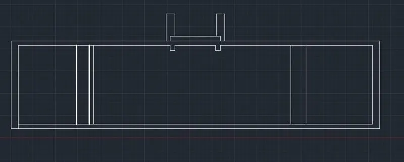
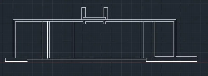
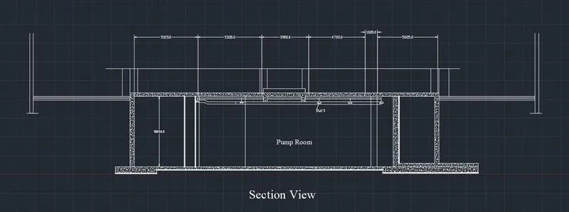
Result:
Create the section view of an industrial building using autocad command and tools as per drawing requires is done.