Creating Kitchen layout, Hatching of Architectural elements and sectional view of an Industrial Building in AutoCad
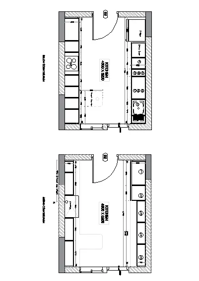
1.Create the layouts of the Kitchen and provide hatches pattern as shown. Also, use blocks wherever required. Provide appropriate dimensions in the plan. Assume the size of doors, appliances and others as per the standards.
Answer:-
step1:- command a xl line and draw vertical line and again command xl line and draw a horizontal line, the two are trim negative directions and use offset with above daigram have dimensions and draw a residential plan.
step2:- command a circle tool used the door shape.
step3:- command a dimlinear and show the dimensions.
step4:- select the separted parts like walls (exterior, interior), doors , caboards, steps, are select individual and apply a different colour for each item.
step5:- command a table tool and select no rows and columns and draw a table.
step6:- command a line tool and draw a reinforcement.
step7:- command a text and enter all the text and save.
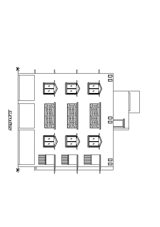
2. Create the elevation of the plan created in the Challenges 7 and apply proper hatch in the walls, doors, windows, and other architectural elements. Refer to the dimensions in Plans and sections in Challenges 7.
Refer to the elevation that needed to be created.
Answer:-
step1:- command a xl line and draw vertical line and again command xl line and draw a horizontal line, the two are trim negative directions and use offset with above daigram have dimensions and draw a residential plan.
step2:- command a circle tool used the door shape.
step3:- command a dimlinear and show the dimensions.
step4:- select the separted parts like walls (exterior, interior), doors , caboards, steps, are select individual and apply a different colour for each item.
step5:- command a table tool and select no rows and columns and draw a table.
step6:- command a line tool and draw a reinforcement.
step7:- command a text and enter all the text and save.
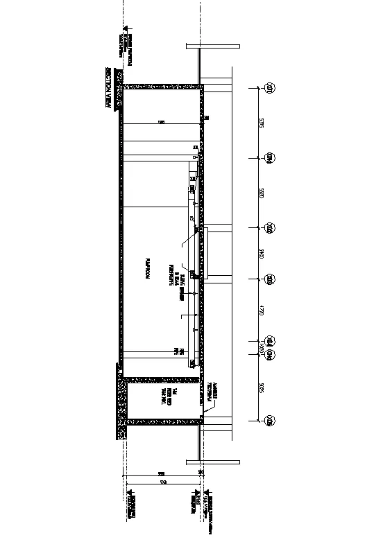
3. Create the section view of an industrial building as shown in Figure. Provide appropriate hatches and dimensions wherever required. Also, provide annotations to the drawing.
Answer:-
step1:- command a xl line and draw vertical line and again command xl line and draw a horizontal line, the two are trim negative directions and use offset with above daigram have dimensions and draw a residential plan.
step2:- command a circle tool used the door shape.
step3:- command a dimlinear and show the dimensions.
step4:- select the separted parts like walls (exterior, interior), doors , caboards, steps, are select individual and apply a different colour for each item.
step5:- command a table tool and select no rows and columns and draw a table.
step6:- command a line tool and draw a reinforcement.
step7:- command a text and enter all the text and save.