Creating Kitchen layout, Hatching of Architectural elements and sectional view of an Industrial Building in AutoCad
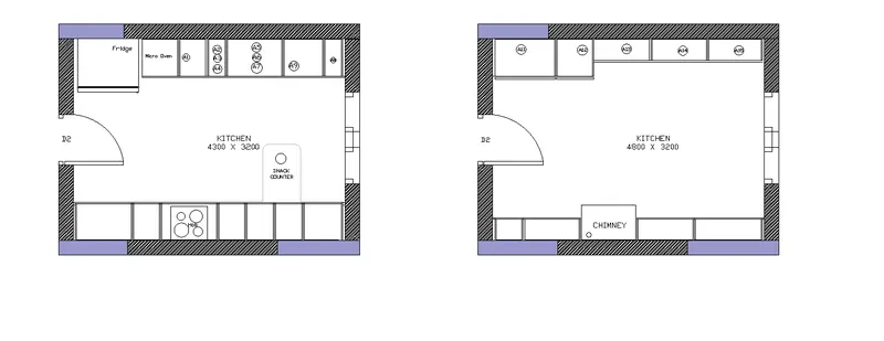
1.Aim: To Create the Kitchen Layout and provide hatches pattern as shown. Also, use blocks wherever required. Provide appropriate dimensions in the plan. Assume the size of doors, appliances and others as per the standards.
Introduction: To create the Kitchen Layout as shown in the Figure and using proper dimension techniques to dimension the kitchen layout and inserting text wherever required. All dimensions are in mm. Assume the size of doors, appliances and others as per the standards
To draw follow the steps below:
Ortho on (F8)
Draw a line of 4760
Draw an offset from the line ata offset distance of 3660
Close the line from both sides
Command OFFSET
Draw an offset from all the corner line at a offset distance of 230 to create a wall around
Command OFFSET
Draw an opening at centre of the left side of 800 to create a door
Command OFFSET
Drawing two openings for window at right side of 575
Command COPY
Copy whole figure using ortho mode at just side of the 1st kitchen plan to make same kitchen plan of same dimensions but in this the inner furniture is different
In 1st kitchen plan:
Draw an offset at a distance of 600
Command:
OFFSET
Specify offset distance or [Through/Erase/Layer] :900
Command:
OFFSET
Specify offset distance or [Through/Erase/Layer] : 450
Command:
OFFSET
Specify offset distance or [Through/Erase/Layer] :900
Command:
OFFSET
Specify offset distance or [Through/Erase/Layer] :450 (3 times)
Command:
OFFSET
Specify offset distance or [Through/Erase/Layer] :560
Command:
TRIM
Trim the unwanted lines
On the opposite side of plan
Command:
OFFSET
Specify offset distance or [Through/Erase/Layer] :850(To make fridge)
Command:
OFFSET
Specify offset distance or [Through/Erase/Layer] :600
Command:
OFFSET
Specify offset distance or [Through/Erase/Layer] :1000
Command:
OFFSET
Specify offset distance or [Through/Erase/Layer] :600
Command:
OFFSET
Specify offset distance or [Through/Erase/Layer] :450
Command:
OFFSET
Specify offset distance or [Through/Erase/Layer] :300
Command:
OFFSET
Specify offset distance or [Through/Erase/Layer] :645
Command:
OFFSET
Specify offset distance or [Through/Erase/Layer] :300
On both sides make an offset of 35 to provide the thickness of the cupboard
Command:
OFFSET
Specify offset distance or [Through/Erase/Layer] :35
Command:
TRIM
Trim the unwanted lines
Command DT
DTEXT
Write the suitable text as given in the figure
2nd kitchen plan
We have copied a same wall layout of kitchen just we have to create furnitures in it
Command HATCH
Providing all the hatch pattern wherever required
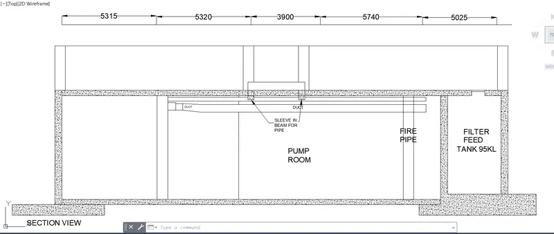
- Aim: To create the section view of an industrial building as shown in Figure.
Introduction: To create the section view of an industrial building as shown in Figure. Provide appropriate hatches and dimensions wherever required. Also, provide annotations to the drawing.
Step 1: Change the colour to the grey i.e. the all projections will be taken can be visualise easily
Step 2: Command XLINE ( vertical )
Take all the projections of the entrance of the plan i.e of first wall, window, veranda, balcony etc
Step 3: Command LINE
Make a line in the bottom
Step 4: Command OFFSET
Make an offset at a distance of 1524mm to make the height of the foundation or footing
Make 3 offsets at a distance of 3316mm to make the height of the all the third floors.
Creating of windows
Step 5: We had already taken projection for windows so by offset command make an offset at a distance 1150
Step 6: Draw an rectangle by using the width as per projection and take height 1200
Step 7: By using Mid point object snap make line between the rectangle inside and parallel to the rectangle
Step 8: Command OFFSET Make an offset of 20 from the rectangle to make the glass of the window
Step 9: Draw an rectangle just below the window to make the window design
Step 10: Draw an triangle using the command POLYGON to make the upper design of window
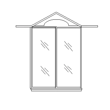
Step 11: Command COPY Copy the window we have drawn to all the floors and where we have take projections
This look like this
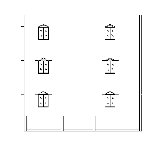
Step 12: Make the lines over the projection line we have drawn
Making of veranda
Step 13: As we have take projection Draw a rectangle by using the width as per projection and take height 1200
Step 14: Make an offset of 50 inside the rectangle
Step 15: Make an offset of 200 to make an rectangle inside to make the glass
Step 16: Make an rectangle above to make the chazza
Step 17: Copy the veranda you have made to all the floors using the perfect projection taken
Making of the Balcony
Step 18: Make the rectangle 964 X 1150 to make the railing
Step 19: By using OFFSET make the railing support
Making of the overhead
Copy the balcony to all the floors
Step 20: Make an rectangle of 3300 X 5100
Inside this rectangle make an door.
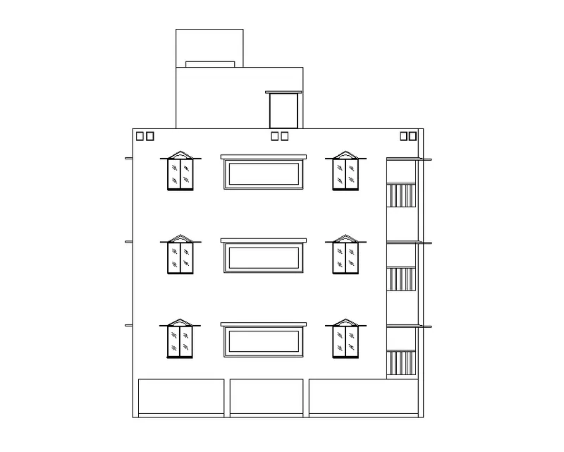
- Aim: To create the section view of an industrial building as shown in Figure.
Introduction: To create the section view of an industrial building as shown in Figure. Providing appropriate hatches and dimensions wherever required and also, providing annotations to the drawing.