Creating Kitchen layout, Hatching of Architectural elements and sectional view of an Industrial Building in AutoCad
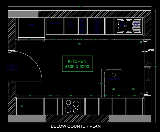
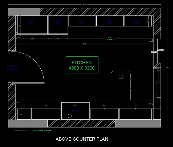
1. AIM : Create the layouts of the Kitchen and provide hatches pattern as shown. Also, use blocks
wherever required. Provide appropriate dimensions in the plan. Assume the size of doors,
appliances and others as per the standards.
- Open the Autocad
- Type unit and selet the decimal unit and precission as 0.0
- Type limits ans specify the lower and upper limits
- Type Z (Zoom) enter and A enter.
- Start for drafting
- All Dimensions are in mm.
COMMAND USED :
- Limits
- Zoom
- Xline
- Line
- Circle (C) command
- X (Explode) Command
- Dimlinear
- Dimstyle
- MLEADER
- Dimcont
- Fillet
- Join
- Object snap
- DT command
- ED command
- MT Command
- Unit command
- LW command
- LT command
- H (Hatch)
- HE (Hatch Edit)
- Offset
- Arc
- Extend command
- Trim command
PROCEDURE :
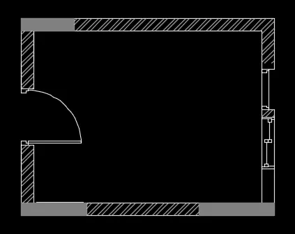
- Type L in command prompt and draw 4300 in X direction and 3200 in Y direction
- Type ‘O’ command and type 250 enter draw the offset towards outside
- Join the lines
- Draw a line 4300 in X direction with 600 in Y direction for slab
- Type ‘O’ command and type 35, 900, 450, 900, 450, 560
- Draw the snack counter of 900 in Y direction and 600 in X direction with the help of dashed line
- Draw a circle in the snack counter in middle
- Draw the offset on the other side also with the offset
- Type ‘O’ command and type 1000, 600, 450, 300, 900, 1145, 35 enter the offset
- Insert the text command and do the detailing
- Do the dimension with the help of ‘DIMLIN’ command
- Do the hatching on the outer wall with the help of ‘H’ command for walls select solids and then the grey colour and for the walls select the pattern hatch.
- Type the mirror ‘MI’ command and select the object and do the mirror of the same drawing and keep the original
- Do the offset as per the drawing
- Remove the dotted line of snack table and make it with solid line
- Draw circle in each cabinet and type the details as mentioned in the drawing
- Draw the door D2 with the line command and with ‘C’ circle command
- Trim all the extra line and half circle
- Type ‘B’ command for block
- Select the specify point or base point
- Save the block with the name D2 and press OK
- Block is inserted do this for both the door

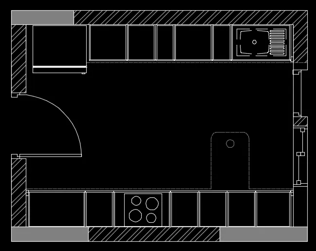
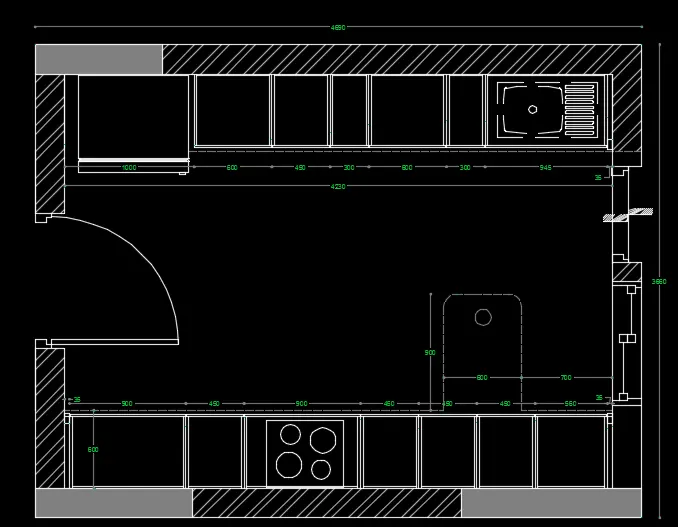
FINAL RESULT :
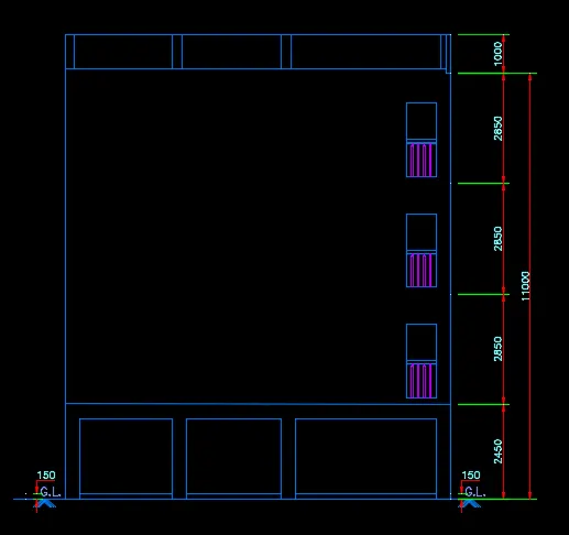
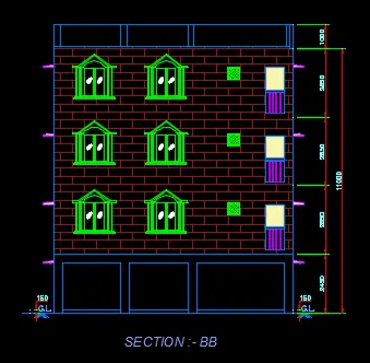
2. AIM : Create the elevation of the plan created in the Challenges 7 and apply proper hatch in the
walls, doors, windows, and other architectural elements. Refer to the dimensions in Plans
and sections in Challenges 7.
- Open the Autocad
- Type unit and selet the decimal unit and precission as 0.0
- Type limits ans specify the lower and upper limits
- Type Z (Zoom) enter and A enter.
- Start for drafting
- All Dimensions are in mm.
COMMAND USED :
- Limits
- Zoom
- Xline
- Line
- Circle (C) command
- X (Explode) Command
- Dimlinear
- Dimstyle
- MLEADER
- Dimcont
- Fillet
- Join
- Object snap
- DT command
- ED command
- MT Command
- Unit command
- LW command
- LT command
- H (Hatch)
- HE (Hatch Edit)
- Offset
- Arc
- Extend command
- Trim command
PROCEDURE :
- Open the file of week 7 where plan is made
- Extend the construction line from every wall, windows, staircase, ventilator chhajja (Elevation is from section BB
- Trim the extra lines where lines are not required
- Draw the frame of the window with the help of line and ARC command
- Type ‘B’ command for block, select the frame
- Select the point and name it as frame and save
- From insert option insert the block and place is at every window
- Select the Hatch option select pattern and then select the bricks
- Click at the wall where hatching is done
- Select the colour
- Right click on the hatch properties then select the size of the hatch pattern
- Elevation is obtained and hatch is done
RESULT
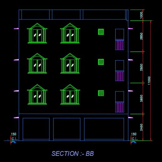
FINAL RESULT
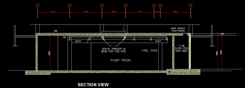
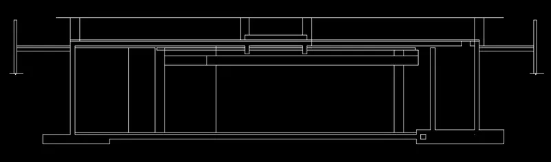
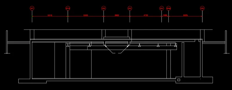
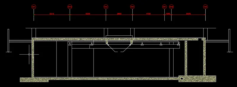
3. AIM : Create the section view of an industrial building as shown in Figure. Provide appropriate hatches
and dimensions wherever required. Also, provide annotations to the drawing.
- Open the Autocad
- Type unit and selet the decimal unit and precission as 0.0
- Type limits ans specify the lower and upper limits
- Type Z (Zoom) enter and A enter.
- Start for drafting
- All Dimensions are in mm.
COMMAND USED :
- Limits
- Zoom
- Xline
- Line
- Circle (C) command
- X (Explode) Command
- Dimlinear
- Dimstyle
- MLEADER
- Dimcont
- Fillet
- Join
- Object snap
- DT command
- ED command
- MT Command
- Unit command
- LW command
- LT command
- H (Hatch)
- HE (Hatch Edit)
- Offset
- Arc
- Extend command
- Trim command
PROCEDURE :
- Type UN in command prompt and select decimal and precisions 0
- Type Limits in command prompt and specify the lower and upper points
- Command ‘Z’ enter, now we are ready for the drafting
- Draw a line with Ortho on 25300 in X direction and 5850 in Y direction
- Type ‘O’ command and to the offset as 230 and select the line left side of vertical line
- Draw a line in X direction 25300 with top line
- Type offset and do the offset 300
- Draw a line in vertical and do the offset of 200
- Type offset and do offset 300 in horizontal line for duct
- Type offset and do offset of 200 from bottom horizontal line for duct
- Type offset and do offset of 100 from top line for sleeve sprayer
- Trim the point at lower left and type @1000<180
- Type @500<270
- Type @2000<0
- Type @300<90
- Type @17055<0
- Type @300<270
- Type @5045<0
- Type @500<90
- Type @300<270
- Type @5850<90
- Type offset and do the offset of 230
- Join all the missing lines and trim all the excess lines
- Type offset and do the offset of 100
- Make hatch help of ‘H’ command and go to pattern and select concrete and do the hatching wherever shown in fig
- Select the hatch command and go to solid and do the hatching wherever shown in fig.
- Select hatch command and go to the pattern and do the hatching at with the horizontal brickwork
- Select the line command and draw the sprayer
- Select the leader command and select the place where arrow is needed and type the text
- Type ‘B’ command and select the sprayer and make as a block and insert the block wherever needed
- Do the dimension of the following using dimension command or ‘DIMLIN’ command
- Insert the circle and copy and paste wherever required
- Insert the text in it
- Do all the finishing by joining and trimming all the lines
- The following drawing is obtained
RESULT
FINAL RESULT