Creating Kitchen layout, Hatching of Architectural elements and sectional view of an Industrial Building in AutoCad
Question 1. Create the layouts of the Kitchen and provide hatches pattern as shown. Also, use blocks wherever required. Provide appropriate dimensions in the plan. Assume the size of doors, appliances and others as per the standards.
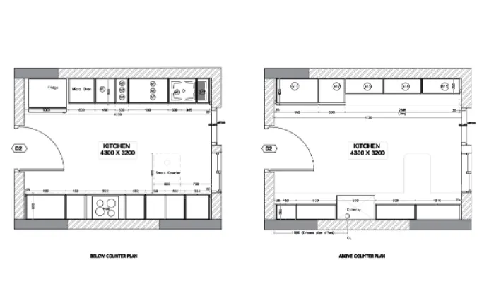
AIM: To create the layouts of the kitchen and provide hatches pattern using the software AutoCAD. And also,use blocks wherever required. Provide appropriate dimensions in the plan using the different commands in the software AutoCAD.
INTRODUCTION: The above figure or layout of the kitchen can be drawn by using the different AutoCAD commands like:
Rectangle command using this command we can draw the outline of the layout.
Explode command can be used for exploding.
Trim command to trim the all unwanted lines.
Erase command to erase the unnecessary objects.
Dimension command used to give the dimensions to the kitchen layout.
Line command to create the lines and many more.
PROCEDURE:
- First of all set the units.
- Type UN in the command line and then press Enter.
- Set the units in the dimstyle to decimal.
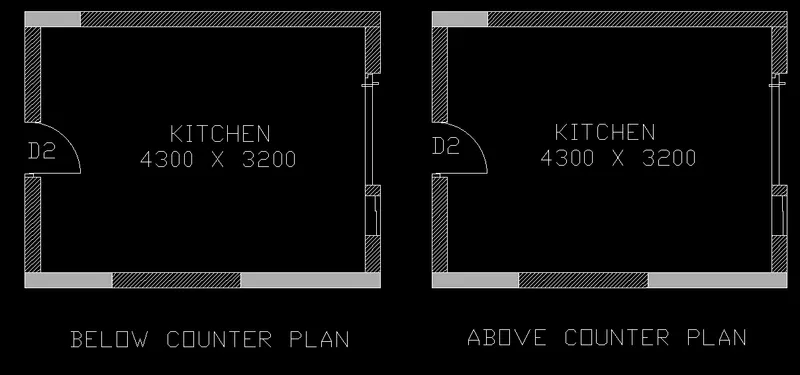
- Now draw a rectangle of 4500 X 3400 and give the offset to the rectangle of 200mm.
- Draw the door of dimension 760 X 2100 mm as shown in the figure.
- Create a text using single text command type "KITCHEN 4300 X 3200" at the centre of the figure.
- Hatch the offset area with two different hatches.
1. ANS131, SCALE = 20.
2. SOLID with transperancy 50.
- Now make two exact copies of this diagram using the copy command.
- Type CO or Copy in the command line and then press Enter.
- Select the base point and copy the rectangle to the different position.
- Write "Below counter plan" and "Above counter plan" below the both diagram.
- Now in the below counter plan draw fridge,various types of shelves,sink,gas stove etc and all these can be drawn by using rectangular tool.
- Just type Rec or Rectangle in the command line and then press enter.
- And also mark the dimensions using dimlinear command.
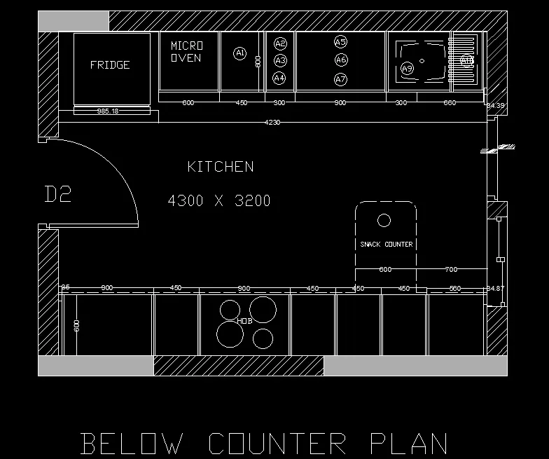
- Similarly in the Above counter plan draw various other shelves,chimney area using the rectangle tool.
- Just type Rec or rectangle in the command line and then press Enter.
- Now mark the dimensions using the dimlinear command. Just type DIMLINEAR in the command line and then press Enter.
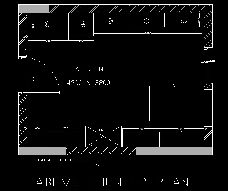
- Text style can be arial and the height for the text is 80mm.
- Now use the layer property to give the layers to objects.
- Just select the layer properties from the ribbon click on the create new option.
- Assign different colours to the different objects.
- Do the same procedure for the other objects in the kitchen layout.
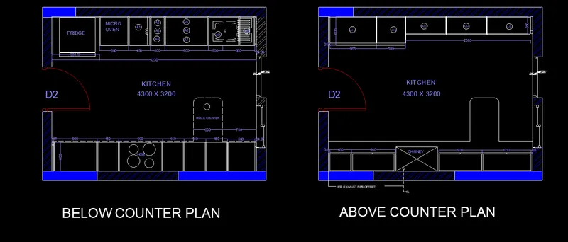
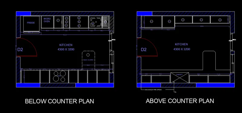
RESULT:
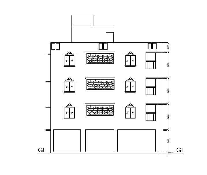
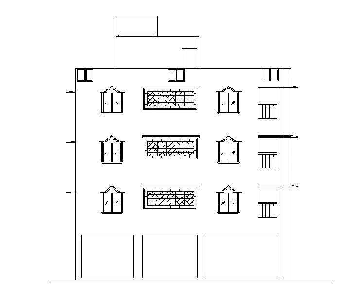
Question 2. Create the elevation of the plan created in the Challenges 7 and apply proper hatch in the walls, doors, windows, and other architectural elements. Refer to the dimensions in Plans and sections in Challenges 7.
AIM: To draw the elevation of the plan created in the Challenges 7 and apply proper hatch in the walls, doors, windows, and other architectural elements.
INTRODUCTION: This drawing can be done by using the xline,line,trim, erase,hatch command in the AutoCAD software.
PROCEDURE:
Setting units:
- First of all open the AutoCAD software .
- Then set the units by typing units in the command line and then press Enter.
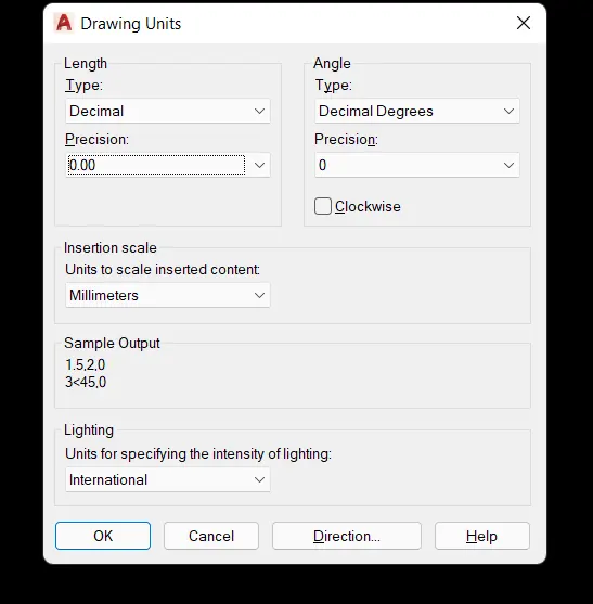
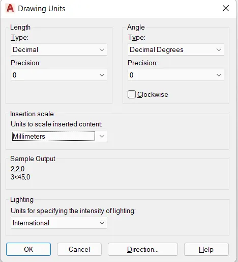
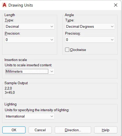
- In the drawing unit dialouge box, select the Decimal in the type, select the precision as 0.
- And in the insertion scale enter milimeters.
- And then press OK.
- After setting the units set the limits by typing LIM in the command line and then press Enter.
- Specify the lower left corner as 0,0. And the upper right corner as the 10000,10000.
- Now type z in the command line and then press enter and then type a and then again press Enter, to zoom out.
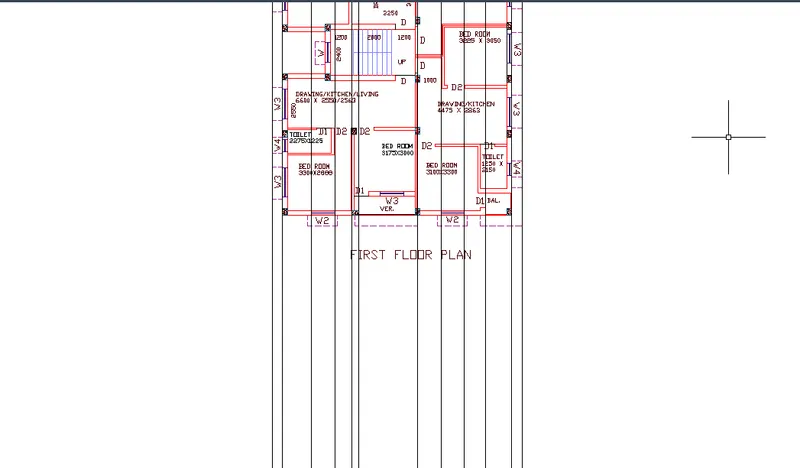
Create the outline.
- To create the outline of this elevation plan select the xl command and draw the extension lines from the plan.
- To use the xl command just type XL in the command line and then press enter.
- Now type V in the command line for the vertical horizontal lines and take the extensions from the plan.
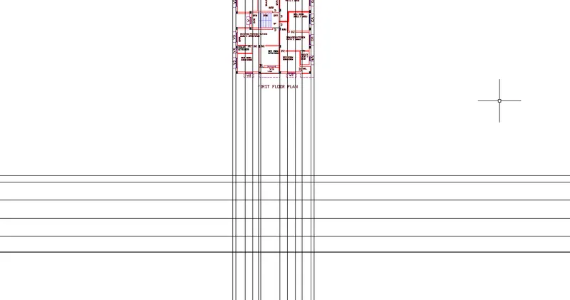
- Now again use the xl command in order to draw the ground level.
- Just type XL in the command line and then press Enter.
- Type H in the command line and then press Enter.
- Draw the ground level with this xl command.
- Give the offset to this line of 150.
- To give the offset just type O in the command line and then press Enter.
- Now specify the offset distance as 150 and then press Enter.
- Now give the offset in the upward direction of the line.
- Now again use the offset command to draw the ground floor,first floor,second floor and the roor.
- To use the offset command just type O in the command line and press Enter.
- Specify the offset distance for the ground level as 2450, for first floor 2850,second floor 2850,for third floor 2850 and for the parapet wall 1000.
- Now give the uppermost line a offset of 600 and then 1200 for the overhead tank.
WINDOWS, Chajjas and the verandah railings and balcony:
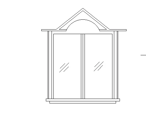
- To draw the window draw a rectangular.
- Then give the offset distance to the sides of the rectangle of 150 distance.
- Then Divide the rectangle into two parts.
- To divide the rectangle use divide command type DIV in the command line and then press Enter.
- In number of segments option just type 2 and then press enter.
- Now the rectangle is divided into two parts.
- Now use the explode command to explode the rectangle created.
- To use the Explode command just type X in the command line and then press Enter.
- Now click on the rectangle created and then press Enter.
- Now the rectangle is exploded.
- After exploding the rectangle give the offset to the middle line of the rectangle.
- To use the offset command type O in the command line and then press Enter.
- Specify the offset distance as 40.
- Now extend the middle line above the rectangle created. Then create a triangle.
- Now draw the arc on the upper side of the window.
- Click on the Arc tool and from there just click on the option Start,End, Direction and create an arc.
- Draw a symbol of glass on the window.
- Window is completed.
- Make this window a block.
- Type B in the command line and then press Enter.
- Now type DOOR in the name option.
- Select a pick point and select the object.
- Then press OK.
VERANDAH RAILING:
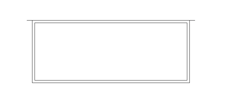
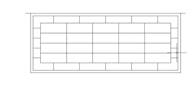
- To draw the verandah railing first of all draw a rectangle using the rectangle tool.
- Just type REC in the command line and then press Enter.
- Now specify the first point and then press d and then enter the dimensions.
- Now the rectangle is created.
- Now use the offset command and give the offset to the rectangle.
- Type O in the command line and then press Enter.
- Now specify the offset distance as 50.
- Now using the trim command and trim the all unwanted lines.
- Type TRIM in the command line and then press Enter.
- And trim the all unwanted lines.
- Now again using the offset command.
- Type O in the command line and then press Enter.
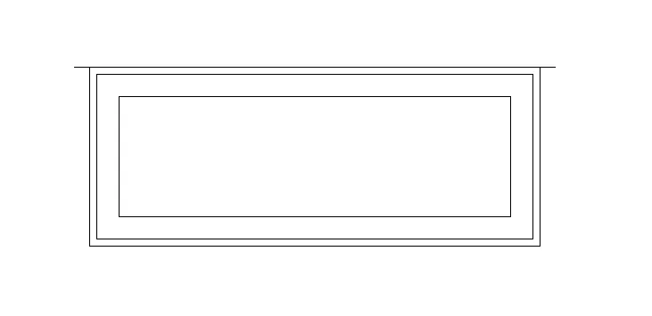
- Specify the offset distance as 150 on all the four sides of the inner rectangle.
- Now using the trim command and trim the all unwanted lines.
- Type TRIM in the command line and then press Enter.
- And trim the all unwanted lines.
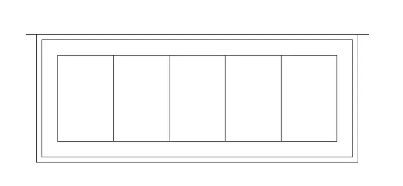
- Now divide the inner rectangle into the 5 segments.
- To use the divide tools just type DIV in the command line and then press Enter.
- Now type the No. of Segments as 5 and then press Enter.
- Again use the divide tool to divide the smaller line of the rectangle into 4 segments.
- To use the divide tools just type DIV in the command line and then press Enter.
- Now type the No. of Segments as 4 and then press Enter.
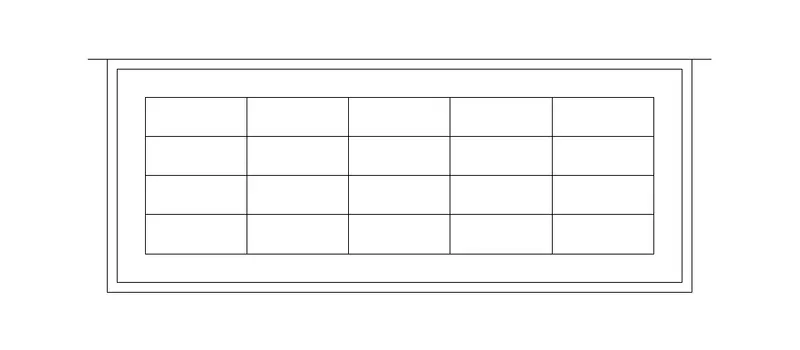
- Draw the lines as shown in the below figure.
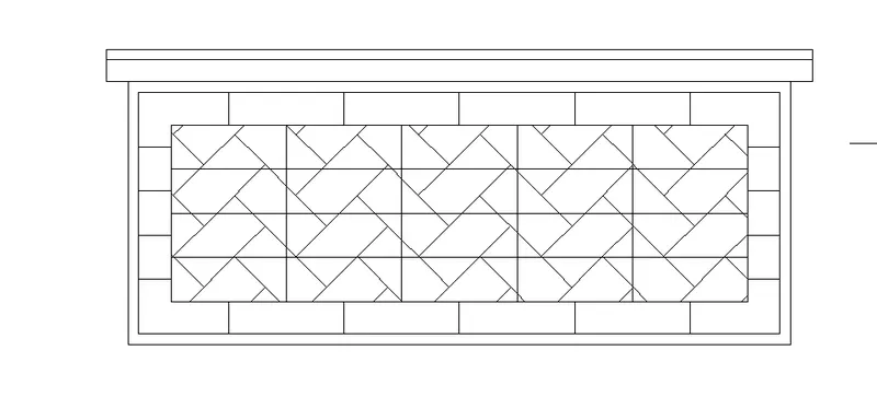
- Now use the Hatch property.
- Type H in the command line and then press Enter.
- Go to the settings and choose AR-B186 and then pick point and enter the hatch in the required location.
- The verandah railing is completely.
TEXT AND DIMENSIONS:
- Now add the text using the text tool.Select the text tool and specify the start point of the text within the walls.
- Specify the height of the text as 100 or any desired height.
- Use the dimlinear tool to add the dimensions at the desired points.
FINAL RESULT:
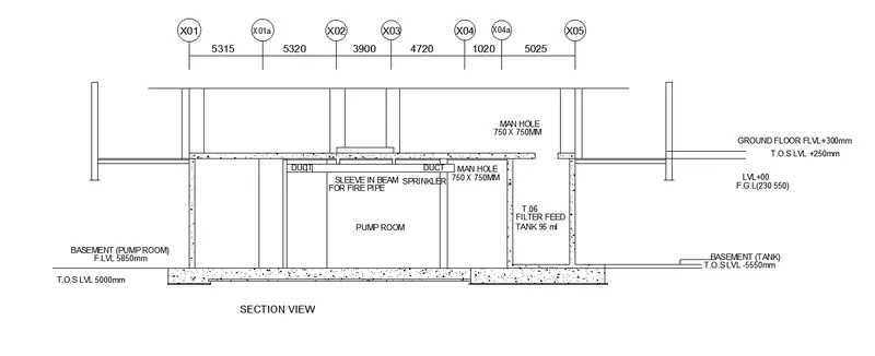
Question 3 . Create the section view of an industrial building as shown in Figure. Provide appropriate hatches and dimensions wherever required. Also, provide annotations to the drawing.
AIM: To create the section view of an industrial building.
INTRODUCTION: This drawing can be done by using the xline,line,trim, erase,hatch command in the AutoCAD software.
PROCEDURE:
Setting units:
- First of all open the AutoCAD software .
- Then set the units by typing units in the command line and then press Enter.
- In the drawing unit dialouge box, select the Decimal in the type, select the precision as 0.
- And in the insertion scale enter milimeters.
- And then press OK.
- After setting the units set the limits by typing LIM in the command line and then press Enter.
- Specify the lower left corner as 0,0. And the upper right corner as the 2000,2000.
- Now type z in the command line and then press enter and then type a and then again press Enter, to zoom out.
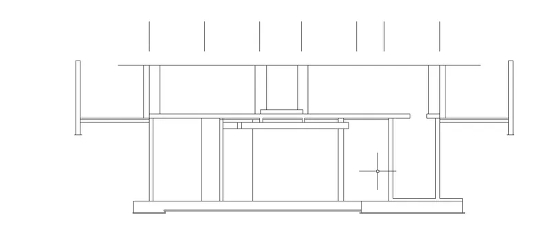
- To draw the section view of an industrial buiding first we have to draw the extended line anywhere on the screen.
- And to draw the extended line just type XL in the command line and then press enter.
- After drawing the XL line on the drawing area use the offset tool and give the offset of 300 to the last line.
- Again using the XL command just type XL in the command line and then press enter
- Type h in the command line and draw the horizontal line on the drawing area.
- Again using the offset command we can offset the line.
- Just type O in the command line and then press Enter.
- Specify the offset distance to the left side as 5315 and give the offset in the inner side of the line.
- Specify the offset distance to the last offseted distance as 5320 and give the offset in the inner side of the line.
- Specify the offset distance to the last offseted distance as 3900 and give the offset in the inner side of the line.
- Specify the offset distance to the last offseted distance as 4720 and give the offset in the inner side of the line.
- Specify the offset distance to the last offseted distance as 1020 and give the offset in the inner side of the line.
- Specify the offset distance to the last offseted distance as 5025 and give the offset in the inner side of the line.
- Now we need to draw the circle at the top of the line with radius 400 and enter the text in the circle using dtext command.
- Type DTEXT in the command line and then press Enter.
- Specify the text height.
- Now enter the text wherever is required.
- Now use the hatch command to hatch the wall.
- Just type H in the command line and then press Enter.
- Go to the settings and choose AR-CONC and then enter.
- The section is ready.
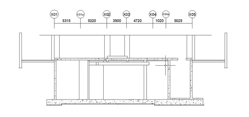
TEXT AND DIMENSIONS:
- Now add the text using the text tool.Select the text tool and specify the start point of the text within the walls.
- Specify the height of the text as 100 or any desired height.
- Use the dimlinear tool to add the dimensions at the desired points.
FINAL RESULT: