Creating Kitchen layout, Hatching of Architectural elements and sectional view of an Industrial Building in AutoCad
AIM:
Creating Kitchen Layout, Hatching of Architectural Elements and Sectional View
of an Industrial Building in AutoCAD
.
OBJECTIVE:
To draw the given sketch of Elevation of Building
Kitchen layout
Industrial Building detail drawing using AutoCAD.
INTRODUCTION:
- Creating the given Kitchen Layout using decimal units i.e., in millimeters
Sketch the given drawing, adding the different layers, dimension & annotation it.
- Creating the given Elevation of Building detail using decimal units i.e., in millimeters
Sketch the given drawing, adding the different layers, dimension & annotation it.
- Creating the given Industrial Building using decimal units i.e., in millimeters
Sketch the given drawing, adding the different layers, dimension & annotation it.
Commands used:
Polyline/Line, Multi-text/Text, Donuts, Offset, Extend, Fillet, Mirror, Trim, Move, Rotate, Annotate.
1). KITCHEN LAYOUT:
PROCEDURE
Step-1: New Sheet-Units-Decimal-precision 0.0 millimeter & OK.
Step-2: Command: REC Rectangle & dimensions are 4734 x 3688 mm.
Command: O Offset, offset it to the distance of 250 mm.
Using Arc & lines the door is drawn.
Using hatch command hatch the model.
Step-3: Command: REC Rectangle > dimensions, to do the fridge Step-3: Command: REC Rectangle > dimensions, to do the fridge.
Command: O Offset, offset it to the desired distance to get the Micro Oven.
Command: T Trim to trim the extras.
Command: O Offset, & offset it to the horizontal distance of 350, 450, 900, 450 & 560.
Command: T Trim to trim the extras.
Command: L Line type & load the dotted lines.
Below Counter Plan
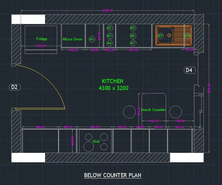
Step-4: command: T Text to text the given annotations
Command: DLI Dim linear is used to name the dimensions.
Above Counter Plan
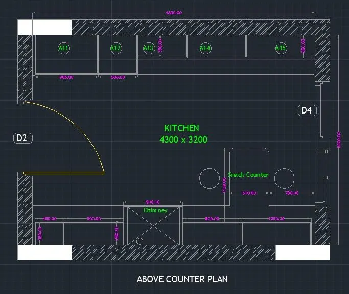
Step-5: Place the all elements of the drawing in the respective layers
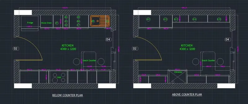
2). ELEVATION OF BUILDING DETAILS:
PROCEDURE
Step-1: New Sheet-Units-Decimal-precision 0.0 millimeter & OK.
Step-2: Using Command: Rec & draw the rectangle
Step-3: Using Command: Arc to draw the Arc.
Therefore, the window is created.
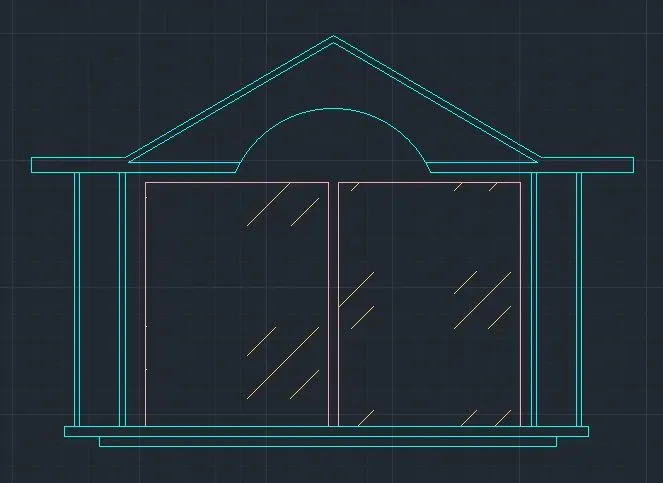
Step-4: Using command: L to draw the lines
Step-5: Using Command: Rec & draw the rectangle.
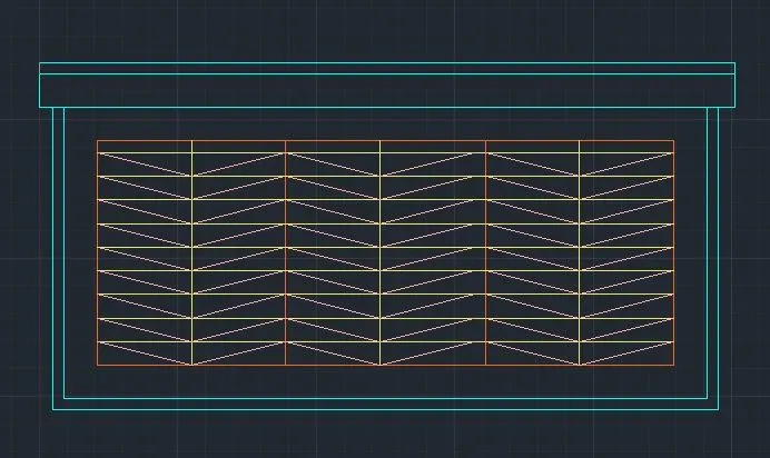
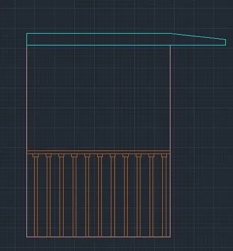
Step-6: Using command: L to draw the lines
Step-7: Using Command: Rec & draw the rectangle.
Step-8: Hatching of objects-
Click the properties panel hatch type list, select the type of hatch that you want to use
On the pattern panel, click a hatch pattern or fill.
On the boundaries panel, specify the how the pattern boundary is selected.
Pick points, inserts the hatch or fill within a closed area that is bounded by one or more objects.
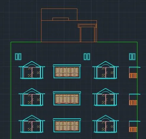
Select boundary objects, inserts the hatch or fill within a closed object.
The selection method is retained until you change it.
Click an area or object to be hatched.
On the ribbon, make any adjustments as needed.
On the properties panel, you can change the hatch type and colors or modify the transparency level, angle or scale for the hatch.
Press enter to apply the hatch and exit the command.
Hatch the brick wall with hatch type as brick and hatch other part of concrete as air concrete.
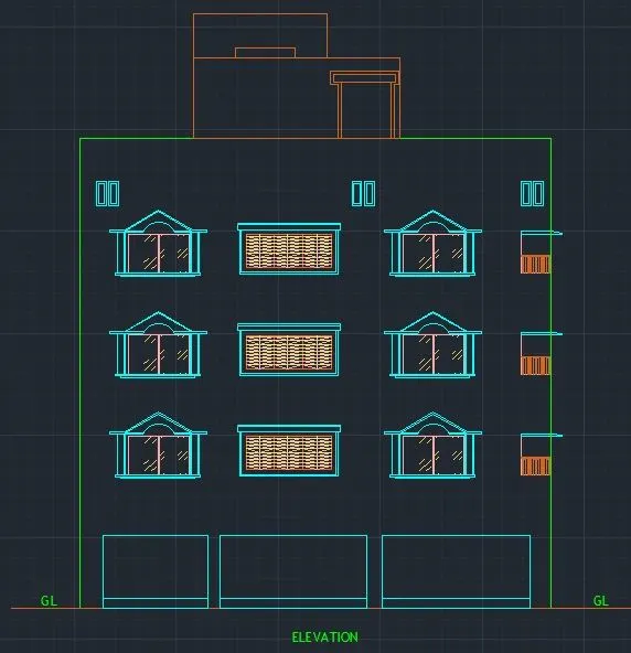
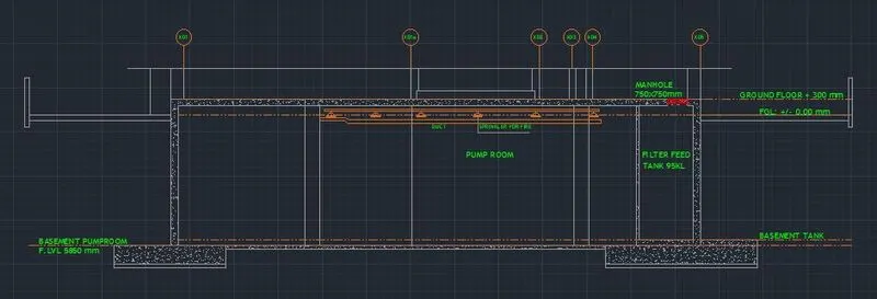
3). SECTIONAL VIEW OF INDUSTRIAL BUILDING DETAILS:
PROCEDURE
Step-1: New Sheet-Units-Decimal-precision 0.0 millimeter & OK.
Step-2: Using Command: L to draw the lines. In the ribbon bar > hatch > AR.CONC
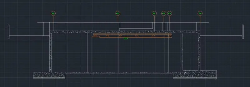
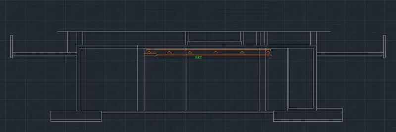
Step-3: Using Command: Rec & draw the rectangle
Step-4: Using Command: LT & draw the dotted line.
Step-5: Using Command: Mt & draft the text.
Step-6: Using Command: C & draw the Circle
Step-7: Mention the Basement pumproom lvl
Step-8: Mention the FGL, Finish Ground lvl
Step-9: Mention the Ground floor lvl.
Step-10: Mention the Filter feed Tank, Pump room, Duct & Fire sprinkler.
RESULT:
- The Kitchen Layout is drawn
- The Elevation & details of a Building is drawn.
- The Sectional View & details of a Industrial Building is drawn.