Creating Conceptual mass in REVIT and Creation of Sinusoidal curve and a Parametric stadium using Dynamo
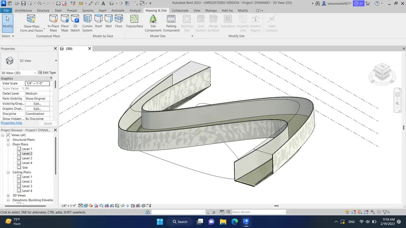
Using Dynamo, create a set of sinusoidal points, a curve, and a surface out of turn.
AIM:
We need to create a sinusoidal point, then the curve from the end, and then create surface
INTRODUCTION:
By using dynamo created a sinusoidal point, then made a curve from the end and converted it into the surface
PROCEDURE:
STEP 1) OPEN DYNAMO
- Open Revit software
- In the new architectural template
- Go to the manage tab, click on dynamo under visual programming
- Dynamo window will open
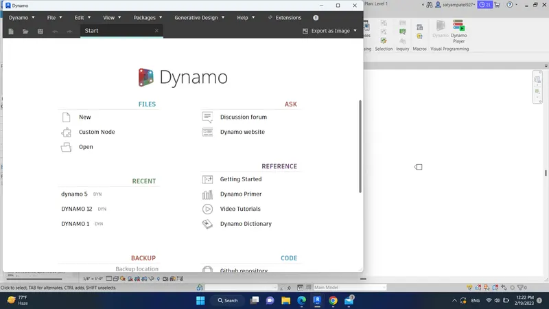
STEP 2) CREATE A NEW FILE IN DYNAMO
- Click on new in the dynamo window
STEP 3) CREATE A SINUSOIDAL POINT
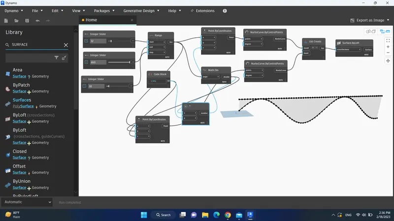
- Insert 3 Integer Slider from Library and rename accordingly for Start, End, and Step
- Insert Range and connect all inputs from Sliders
- Insert Point.ByCoordinate and connect “X” with seq (output of Range)
- Insert Math. sin and provide input from seq (output of Range)
- Insert Multiplication and CodeBlock (renamed with Curve)
- Provided inputs for multiplication from Math. sin and Curve
- Insert one more Integer Slider (renamed with Y-Point) and one Addition
- Provided inputs for addition from Y-Point and Multiplication
- Given the output of addition to “z” point of Point.ByCoordinate
STEP 4) CREATE A CURVE
- Insert NurbsCurve.ByControlPoints
- Provided input to NurbsCurve.ByControlPoints from the output of Point.ByCoordinate
- This will create Curve on the Sinusoidal points
STEP 5) CREATE A CUSTOM NODE
- Select all Output Nodes
- Go to Edit > Create Custom Node
- Provided the Name of the node as SinWave
- Provided Description as Sine Wave Curve and Category as Revit
- Click on OK
STEP 6) CREATE SURFACE
- Copy all the input nodes and output nodes and past them two times
- Change the value of Y-Points
- Insert one List and provide the output of SinWave as an input to the List
- Insert one Surface.ByLoft and provide the output of List as Input of Surface.ByLoft
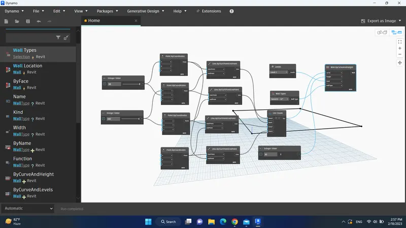
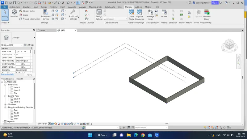
2) Create a conceptual layout of the floor plan in dynamo. Using the tools available in dynamo, link the lines to appropriate model elements in Revit by choosing the wall types and parameters. Use the sliders to slide through the wall's height and length.
AIM:
By using dynamo created a conceptual wall layout of the floor plan
INTRODUCTION:
To create the conceptual layout of a floor plan in dynamo, I used available tools for joining the line, wall type, and floor type and used sliders for the height and length of the wall
PROCEDURE:
STEP 1) OPEN DYNAMO
- Open Revit software
- In the new architectural template
- Go to the manage tab, click on dynamo under visual programming
- Dynamo window will open
- Create a new dynamo model
STEP 2) CREATE A POINT
- Insert two integer sliders and rename them with x and y
- Insert 4 Points.ByCoordinates and rename them accordingly, i.e., (0, 0, 0), (0, y, 0), (x, y, 0), (x, 0, 0)
- Connect the output of integer sliders as an input of Point.ByCoordinates accordingly
- 4 points created, based on the length and width.
STEP 3) CREATE A LINE
- Insert 4 Lines.ByStartPointEndPoint
- Provide output Point.ByCoordinates as an input of Line.ByStartPointEndPoint to connect the line between points accordingly
STEP 4) PROVIDE THE LEVEL, WALL TYPE, AND HEIGHT OF THE WALL
- Insert a List Create and add the four items to the list
- Connect the outputs of each Line.ByStartPointEndPoint to one-by-one list items
- Insert Levels and select the level1
- Insert the Wall Type and choose the wall type as Generic 6” Masonry
- Insert Integer slider and rename as Hight and change the Hight as required
- Insert Wall.ByCurveAndHight and provide the inputs from List, Level, Wall Type, and Hight.
STEP 5) PROVIDE FLOOR TYPE
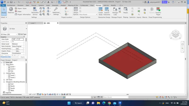
- Insert Floor Type and select Wood Joist 10” – Ceramic Tile
- Insert Floor.ByOutlineTypeAndLevel
- Provide the input for the Floor.ByOutlineTypeAndLevel from List, Floor Type, and Level
Answer3
AIM:
Need to create an array of elements in Revit and vary the properties by using a slider or code block in dynamo
INTRODUCTION:
Created the array of columns in Revit and, by using the integer slider from the dynamo, rotated the column in Revit
PROCEDURE:
STEP 1) OPEN REVIT AND CREATE AN ARRAY OF COLUMN
- Open Revit software
- In the new architectural template
- Go to architecture and select the architectural column
- Insert four columns as shown
STEP 2) OPEN DYNAMO
- Go to the manage tab, click on dynamo under visual programming
- Dynamo window will open
- Create a new dynamo model
STEP 3) CREATE ROTATION IN DYNAMO
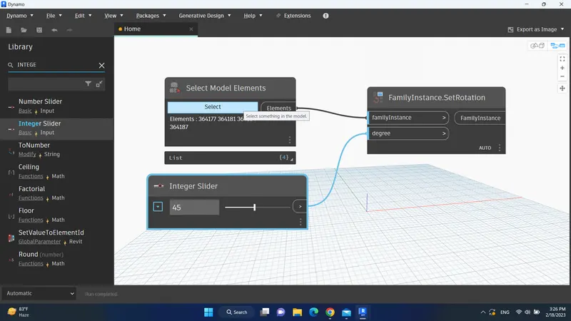
- Insert Select Model Elements
- Click on Select and select all the columns from Revit
- Insert the Integer Slider and provide the angle to the slider
- Insert FamilyInstance.SetRotation and provide inputs from Select Model Element and Integer Slider
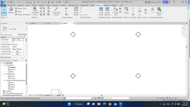
4) Create a conceptual mass in Revit, develop a parametric column by dividing the surfaces, and apapplyinghe the concepts similar to parametric walkway modeling. Use triangular bent or square-shaped panels to add a finish to the parametric column
Answer4
AIM:
Create the Conceptual Mass in Revit, create a form, and use the property of a triangular bent icon in the parametric column
INTRODUCTION:
Created a Conceptual Mass and developed a parametric column by dividing the surface and finishing the model by using a triangular bent shape
PROCEDURE:
STEP 1) OPEN CONCEPTUAL MASS
- Open Revit software
- Go to File tab > from new select Conceptual Mass
- Select Metric Mass from the Conceptual Mass folder > click Open
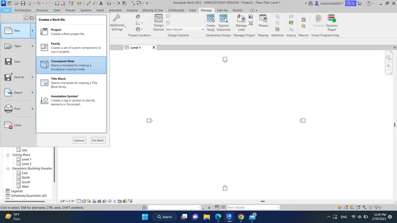
STEP 2) CREATE A SPLINE COLUMN LINE
- Go to the east elevation
- Click on a model from modify tab, then select pick a line from the draw tool
- Provide offset of 12’ from Level 1
- Go to level 1 floor plan
- In create tab, select spline from the draw tool and create 4 points
STEP 3) CONVERT INTO PARAMETRIC SOLID FORM
- In 3D view, select created column line
- Set plane at each created point
- Select a polygon and create at all points with a mass of 12.’
- Again, select created column line and the first polygon
- In modifying tab, dropdown create form and select a solid form
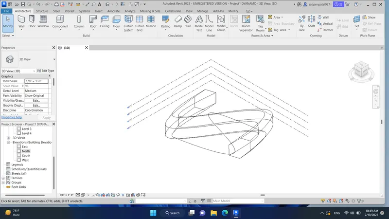
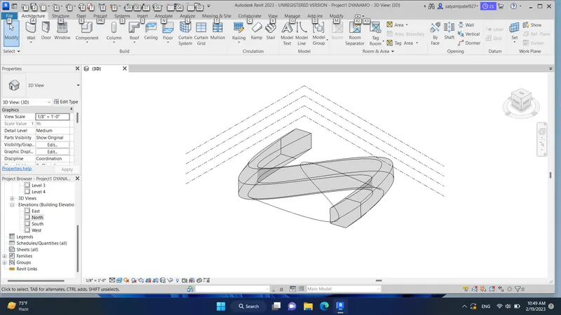
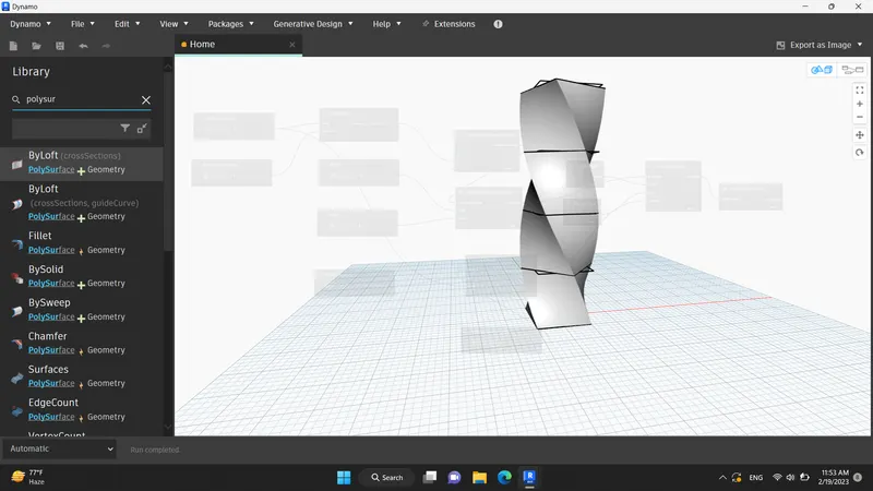
5) Use Dynamo to work on developing a Parametric Stadium. List your parameters and use the visual programming approach to complete the modeling; you can use the concepts discussed in the parametric high-rise tower in class for reference.
Answer 5:
AIM:
By using dynamo created a conceptual wall layout of the floor plan
INTRODUCTION:
To create the conceptual layout of a floor plan in dynamo, I used available tools for joining the line, wall type, and floor type and used sliders for the height and length of the wall
PROCEDURE:
STEP 1) OPEN DYNAMO
- Open Revit software
- In the new architectural template
- Go to the manage tab, click on dynamo under visual programming
- Dynamo window will open
- Create a new dynamo model
STEP 2) PROVIDE HEIGHT AND LEVELS
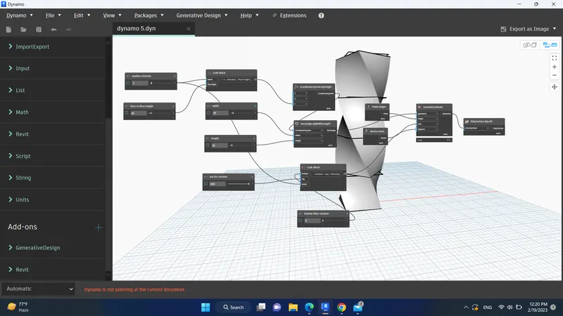
- Insert 4 Integer Slider and rename it, i.e., Levels, Height, Top floor Rotation, Bottom floor Rotation.
- Insert Code Block and provide code as “0..#Levels.FloorHeight”
STEP 3) PROVIDE HEIGHT AND LEVELS
- Insert CoordinateSystem.ByOrigin
- Provide the output of the code block as an input to the z point of CoordinateSystem.ByOrigin
- Change the no of Level and Height to is integer slider
- This will create a level on the z-axis
STEP 4) PROVIDE HEIGHT AND LEVELS
- Insert 2 Integer Slider and rename with Width and Length
- Provide appropriate value to the sliders
- Insert Rectangle.ByWidthLength
- Provide input to Rectangle.ByWidthLength from Width, Length, and CoordinateSystem.ByOrigin
- It obtains the rectangle on the z-axis level
STEP 4) PROVIDE HEIGHT AND LEVELS
- Insert 2 Integer Slider and rename with Width and Length
- Provide appropriate value to the sliders
- Insert Rectangle.ByWidthLength
- Provide input to Rectangle.ByWidthLength from Width, Length, and CoordinateSystem.ByOrigin
- It obtains the rectangle on the z-axis level
STEP 6) CREATE SURFACE
- Insert PolySurface.ByLayout
- Provide input from Geometry. Rotate