Creating a Floor plan, Footing detail and Isometric view using AutoCad
First, Choose the rectangular tool.
Let's assume rectangular Specify First point is (1,1) put dimension is @0.90, 0.25. and choose a line tool to make load Bearing over spread footing
and decide to specify the point of rectangular take dimension X axis is 0.25 and go Y axis dimension is 0.40.
again take X AXIS as 0.05 and measure the Y axis as 0.40.
Again take the X axis as 0.05 and take the last point of specifying the point of making rectangular so choose rectangular tool are dimension is (@0.30,0.60). And the end of the rectangle, we take a specific point of the polyline, so let them choose the polyline tool. Take X's positive direction is 0.05, and Y's downward direction point is 0.4. Again take X's negative direction is 0.05, and Y's downward direction is 0.4.and let's choose the rectangular tool, and the dimension is (@0.3,0.60). Again select the rectangular dimension (@0.3,0.05) and choose the rectangular tool again. Dimension is (@0.3,1), and another rectangular is (@-1.15,-0.03). Select polyline and starting point of the polyline is rectangular endpoint go X positive direction 0.3 and Y Upward direction is 0.15 And again do the same thing in 4 times.
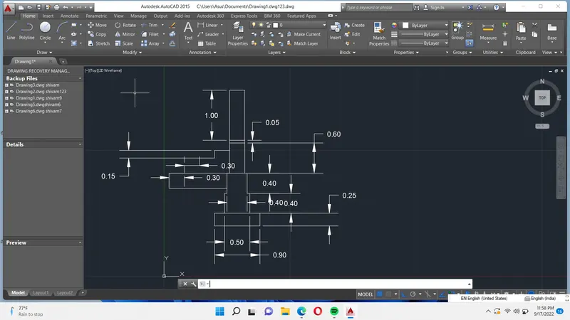
C.S OF LOAD BEARING WALL OVER SPREAD FOOTING
Picture - 2
First, Choose the line tool.
Let's assume line Specify the First point is (1,1) and Y axis upward direction dimension 0.15.
The next specified line point is (@0.38,0.25), and take the polyline tool. Y upward direction dimension 1.60 and x-axis positive direction is 0.24 and goes Y-axis downward direction goes 1.60 and polyline point is/8
Polyline (@0.38,0.25) and goes Y-axis downward direction is 0.15 and close. Again specified polyline point is (1,1) and goes the X-axis 0.04 and 0.04 Y axis upward direction, and 0.38 goes X-axis positive direction. And Y-axis upward to end of the line and escape the same process do another side of footing and draw a line below 0.20 upper side of the isolated footing and take offset tool distance 0.20 up to 10 times.
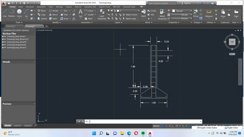
C.S ISOLATED FOOTING
Picture - 3
First, Choose the polyline tool.
Let's assume the line specifies the polyline's first point (1,1) first goes to the Y axis upward direction is 4.2, and the next goes x axe negative direction is 0.9.
And Y-axis upward direction is one, then X Axie positive direction is 0.9.
and goes Y axis upward direction is 3.60 and X positive direction 3.6 and Y axis downward direction 3.6 again goes X-axis positive direction 0.9.
and goes y downward direction is one and goes negative X direction 0.9, and again y downward direction is 4.2 and choose close.
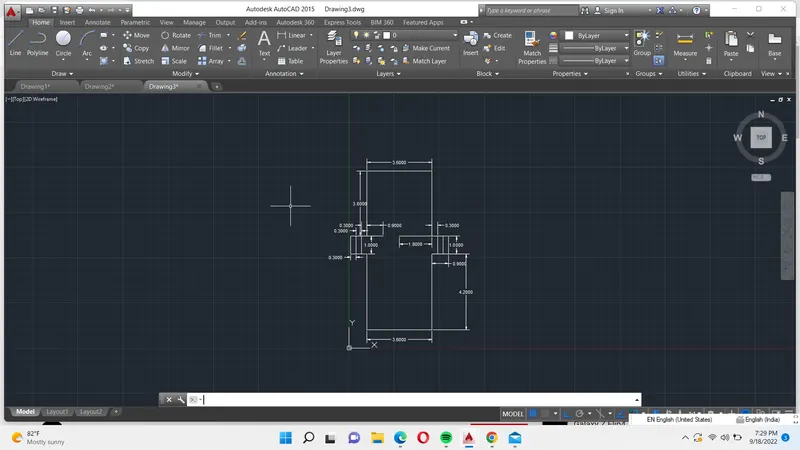
LINE DIAGRAM OF A TWO BEDROOM BUILDING
Picture - 4
First, Choose the polyline tool.
Let's assume the line specifies the polyline's first point (1,1). And go to y-axis upward direction and dimension is 0.9 and goes X-axis positive direction is 0.45 and again goes 0.15 Y-axis Downward direction.
And goes 0.4 X-axis positive direction and 0.05 Y-axis downward direction. Then it goes 0.3 X-axis positive direction and goes 0.05 y-axis downward direction and again goes 0.4 x-axes positive direction and 0.05 y axe downward direction. Then go 1.0 X-axis positive direction and 0.30 y-axis downward direction. Now go 1.0 X-axis negative direction and go 0.05 y axis downward direction and again goes 0.60 X-axis negative direction and 0.05 Y axis Downward direction. Then it goes 0.3 X-axis negative direction and goes 0.05 Y-axis downward direction. 0.4 x-axis negative and 0.25 Y-axis Downward direction. And go 0.45x-axis negative, and last, choose the close tool.
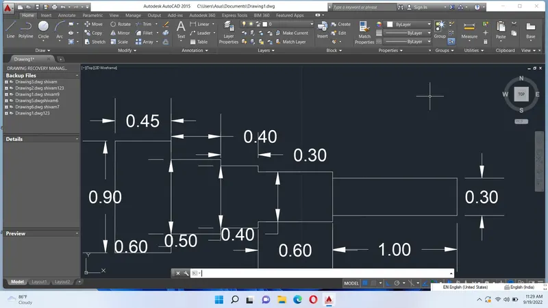
C.S LOAD BEARING WALL SHOWING FOUNDATION DETAILS
PICTURE - 5
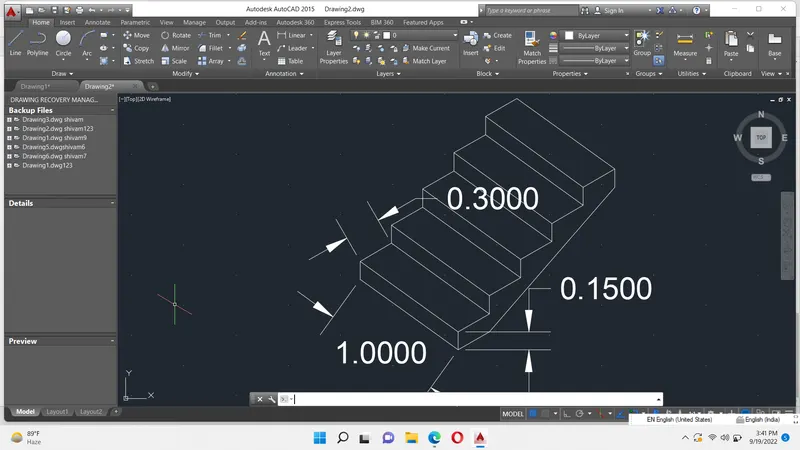
ISOMETRIC VIEW OF STEPS