Creating Conceptual mass in REVIT and Creation of Sinusoidal curve and a Parametric stadium using Dynamo
Creating Conceptual mass in REVIT and Creation of a Sinusoidal curve and a Parametric stadium using Dynamo
Introduction:
Dynamo is an open-source visual programming language for Revit, written by designers and construction professionals. It's a programming language that allows you to type lines of code; while also creating an algorithm that consists of nodes.
Using dynamo work can be carried out with enhanced BIM capabilities in Revit. Dynamo and Revit can together be utilized to model and analyze complex geometries, automate repetitive processes, minimize human error, and export data to excel and other file types. Dynamo can make the design process more efficient with an intuitive interface and many pre-made scripting libraries available as well.
The user interface for dynamo is organized into five main areas, the largest being the workspace where programs are processed and these user interface sections include
- Main Menu
- Toolbar
- Library
- Work Space
- Execution Bar
The workspace is the place where designers develop visual programs but it is also the place where any elaborate geometry is previewed.
The conceptual mass of a building contains different types of parameters like level, floor area, and floor perimeter and the architect can generate early quantities takeoff from the mass. In Bim modeling services the conceptual mass of a building can be exported to any other format for performing early energy analysis.
1.
Aim:
To create a set of sinusoidal points, a curve, and a surface out of the curve using dynamo.
Procedure:
- Initially, open the architecture template of Revit software and go to the manage tab.
- In the manage tab select the dynamo.
- Then the dynamo window opens and then go to the new option.

- Now, search points by coordinates in the search panel.
- Then, connect the range block to the x coordinate of the point by coordinate block.
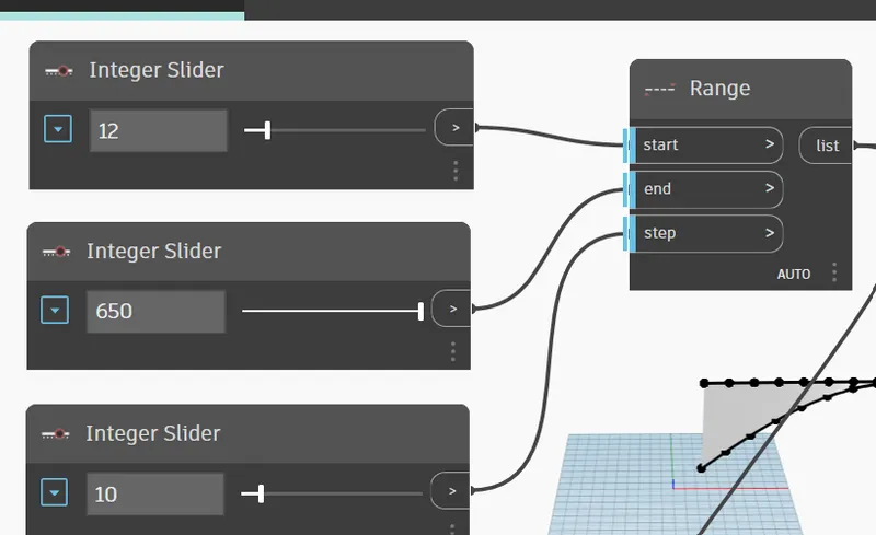
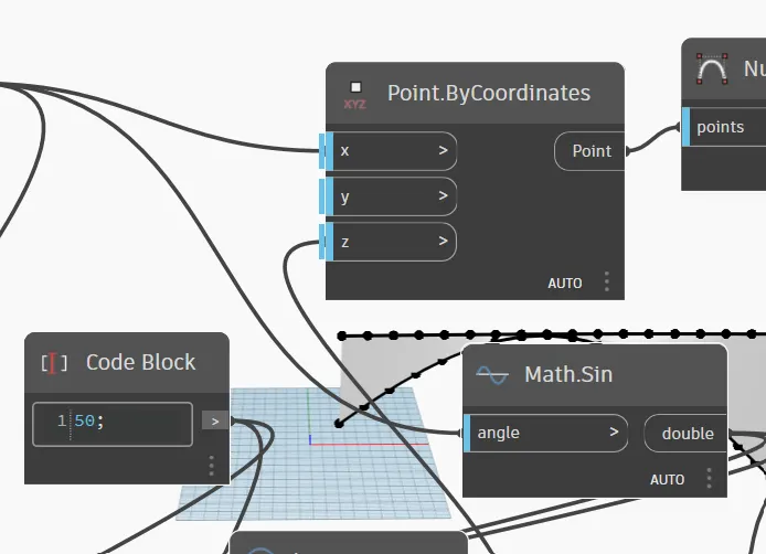
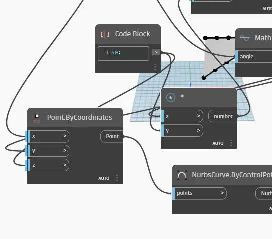
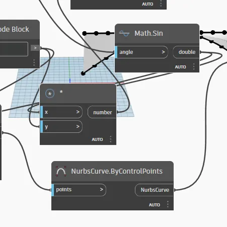
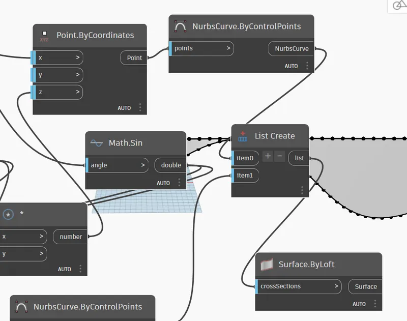
- Hence, the set of sinusoidal points is obtained.
- Now, we have to convert them to a curve.
- The curve can be created from the NURBS curve.
- Search Nurbscurve in the library and choose NURBS curve by control points
- Now, connect the Points by coordinate block as input for the NURBS curve. A line will be developed connecting the points.
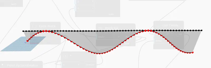
- Hence, the surface is developed out of the curve.
2.
Aim:
To create a conceptual layout of a floor plan in dynamo.
Procedure:
- Open a new architectural template.
- Go to manage tab and open the dynamo --> New.
- To create the wall first we have to create four control points.
- For this, search points by coordinates in the search panel of the library.
- 1st one is named as the origin (0,0,0) and the rest is named control point 1(x,0,0), control point 2(0,y,0) and control point 3(x,y,0).
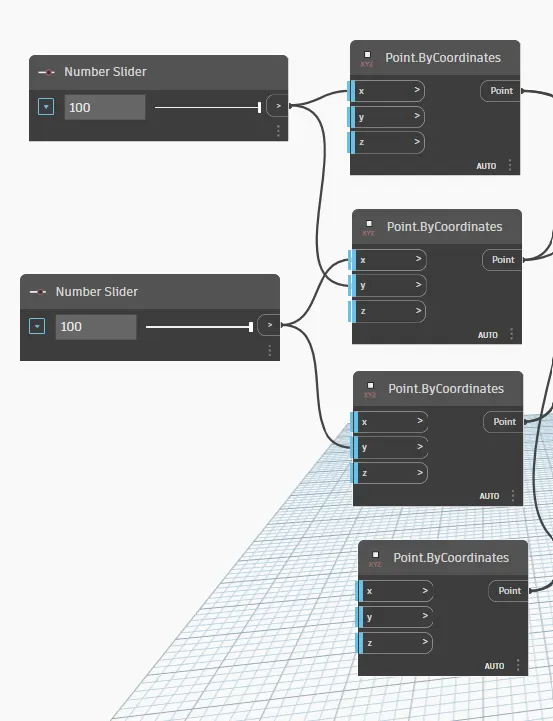
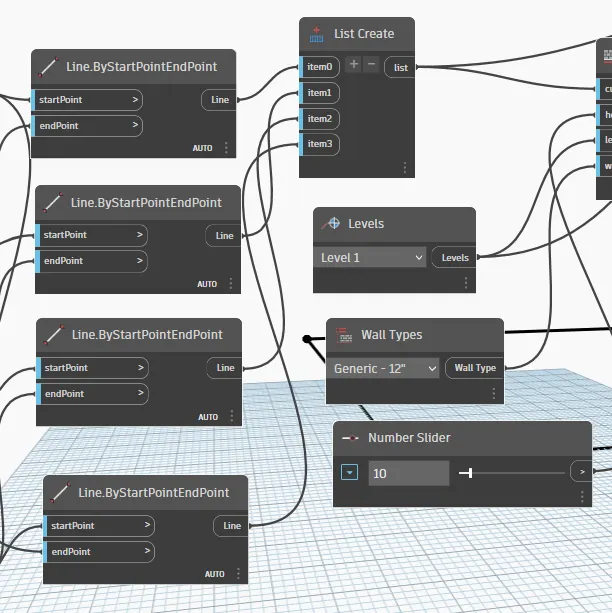
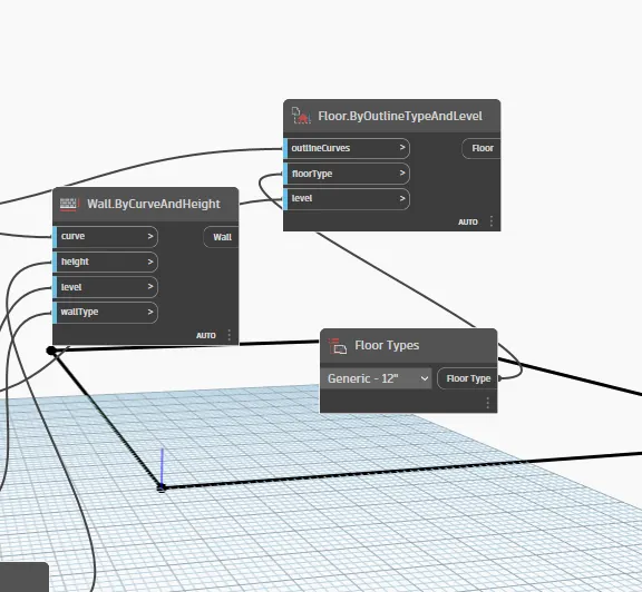
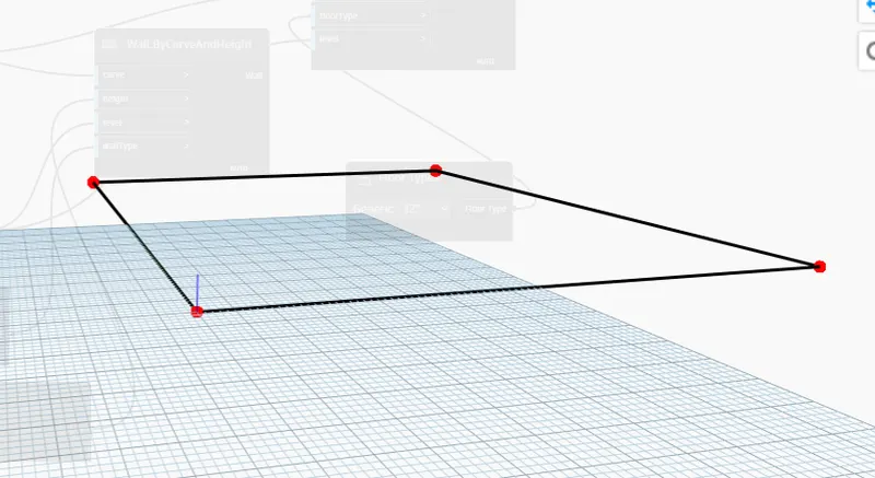
- The height of the wall can be adjusted using the slider.
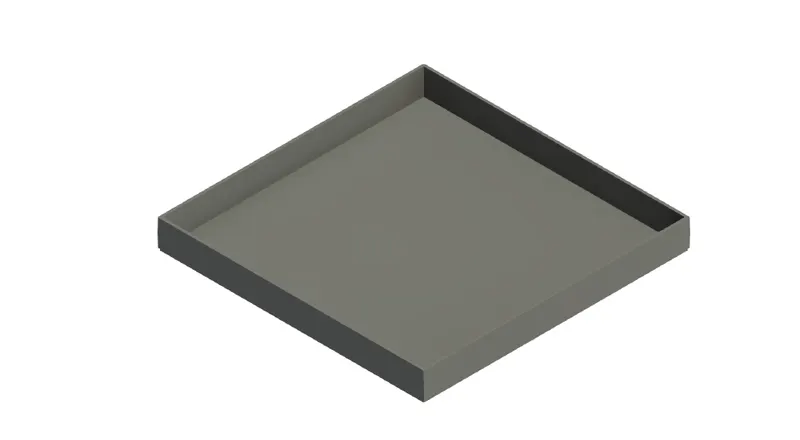
- Now, we have to place the floor.
- For this, type floor in the library and select floor by outline curve, floor type, and level.
3.
Aim:
To create an array of model elements in Revit.
Procedure:
- Open a new architectural template in a Revit file.
- In that go to architecture tab --> Columns --> Architectural column --> Place the column
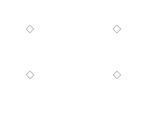
- Now, similarly 16 columns are created.
- The properties of the model elements are varied using dynamo.
- Now, open dynamo.
- In the search panel of the library search select model elements, integer slider, and set rotation.
- The integer slider is renamed as rotation angle.
- Now, the select model elements block will be the input for the family instance and the integer slider ( rotation angle) will be input for the degree.
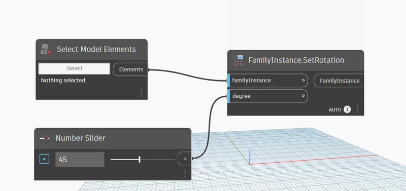
- The rotation angle can be varied to the desired value.
Result:
The array of model elements has been created and their properties are being varied through the blocks created in dynamo.
4.
Aim:
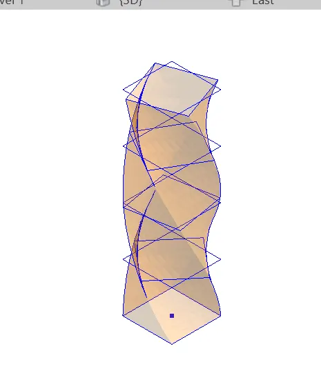
To create a conceptual mass in Revit and develop a parametric column by dividing the surfaces.
Procedure:
- Open Revit software and under the families open a new --> conceptual mass --> mass.
- Now, go to an elevation view and create a level at 3.6m and name it the Height of the roof.
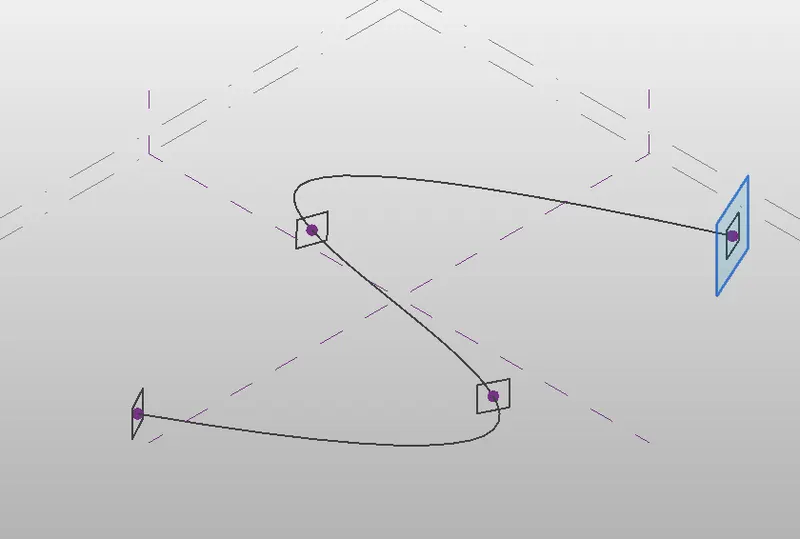
- Now, using the spline tool draw the desired outline for the walkway.
- Now, we have to create a profile to sweep through the curve.
- For this, we have to set the workplace at the points and develop a polygon at the workplace keeping the point as the center.
- Now, a polygon is developed with a point as the center.
- Similarly, workplace and polygon are developed at all the nodes.
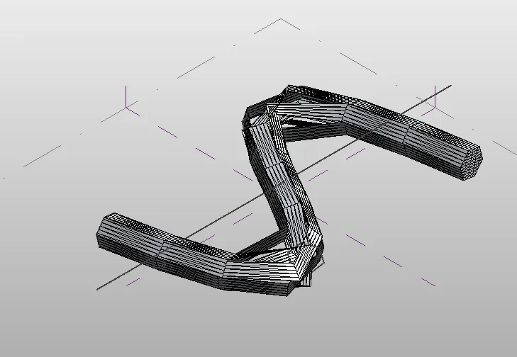
- Now, we have to create the surface which is done through a sweep.
- For this, select all the polygons and the curve line and choose to create form option.
- Now, select the entire form of the walkway and filter it to retain only the divided surface.
- Then in the pattern select the family that we have created just now.
5.
Aim:
To develop a Parametric Stadium using dynamo in Revit.
Procedure:
- Initially open a new architectural template in Revit and then open dynamo.
- Basic parameters to design a high-rise structure are created as input in dynamo.
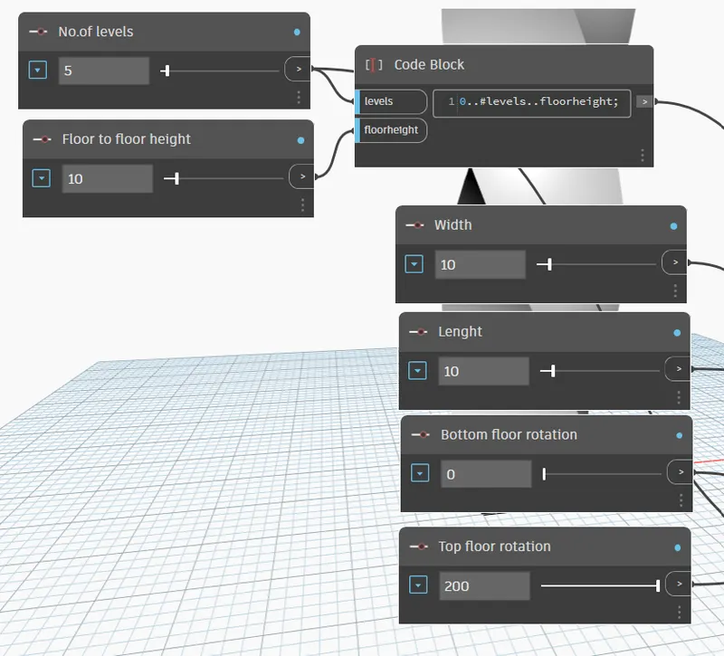
- Four integer sliders are taken from the library for the following:
- Number of levels
- Floor-to-floor height
- Bottom floor rotation
- Top floor rotation
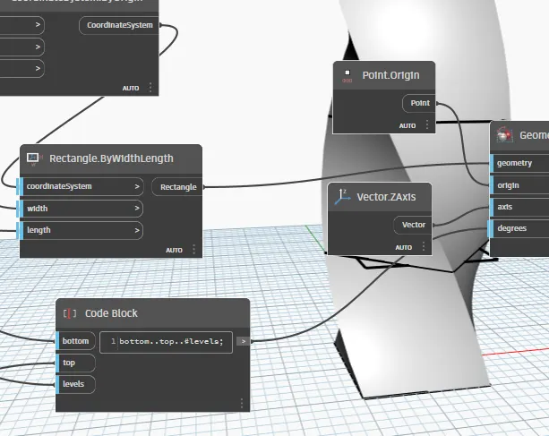
- Now, insert a code block from the library to combine level and floor-to-floor height and type 0..#levels..Floor height.
- Now, connect the integer sliders named levels and floor-to-floor hegiht as input to the code block.
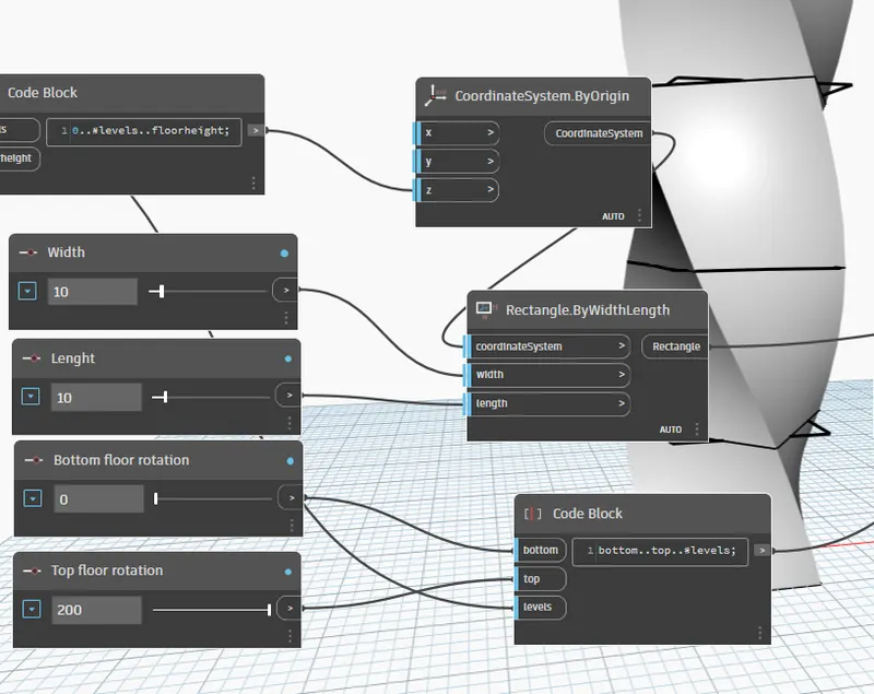
- Now, search coordinates by origin in the library and insert it.
- Then connect the code block as input for z coordinate in the coordinate by origin block.
- Five points are generated corresponding to 5 levels.
- Now, insert rectangle by width and length from the library.
- For this, inputs requied are coordinate system, length and width.
- So insert integer slider for length and width.
- Then connect the inputs for the rectangle block.
- Now we have to rotate the geometry.
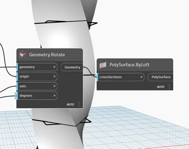
- So, for this insert the rotate block from the library. The inputs required are:
- Geometry : Rectangle block
- Origin: insert an origin block from the library.
- Axis: insert vector Z axis from the library.
- Degrees: For this insert a code block and type Bottom..Top..#level. The inputs for this code block is already available i.e, Bottom floor rotation, top floor rotation and levels.
- Now, we have to create surface, for this type surface by loft in library.
- Then connect Geometry.rotate block as input for Surface by loft.
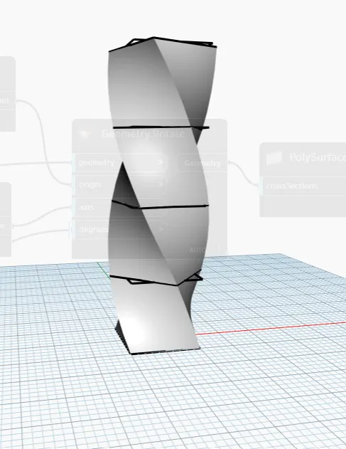
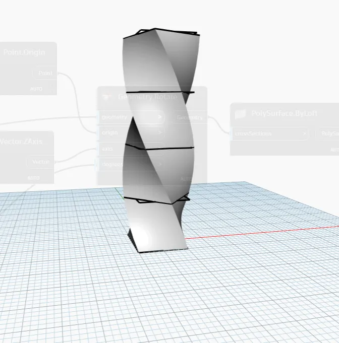
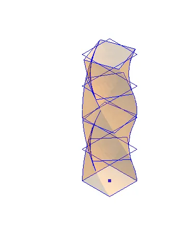
- Hence, the parametric stadium have been created.
- The number of levels and width and length of the rectangle can varied accordingly.
Result:
The Parametric Stadium have been created and is as given below: