Creating Conceptual mass in REVIT and Creation of Sinusoidal curve and a Parametric stadium using Dynamo
1) Using Dynamo create a set of sinusoidal points and create a curve and create a surface out of the curve.
AIM: - To create a set of sinusoidal points, a curve and a surface out of the curve using dynamo.
INTRODUCTION: - Creation a set of sinusoidal points, curve and to creation a surface out of the curve is going to be explained in detail with step-by-step procedure.
PROCEDURE: -
- Open Revit 2023.
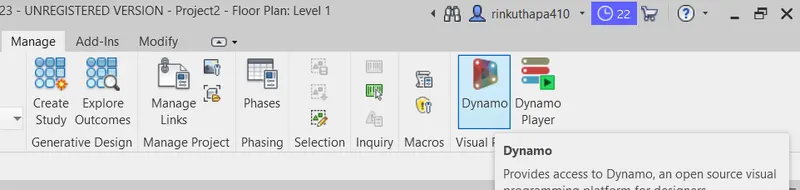
- Go to Manage Tool.
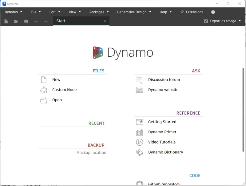
- Open Dynamo in Visual programming.
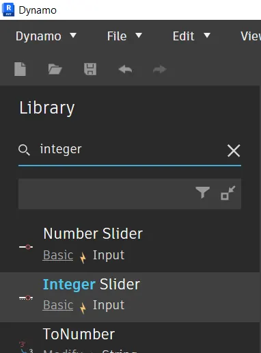
- By searching integer in the search bar invoke the integer slider and put it in drawing screen
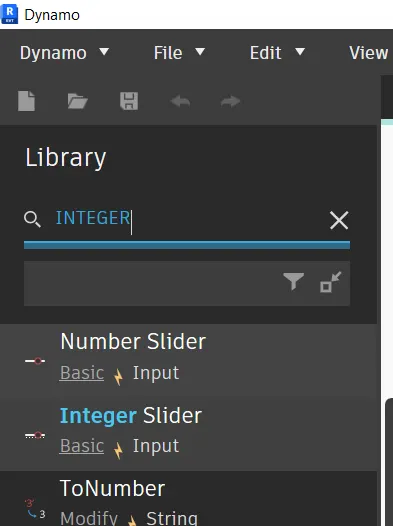
- place the integer slider thrice in the drawing sheet
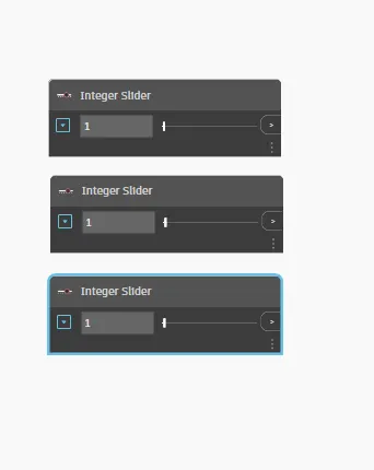
- provide the value as per the requirement
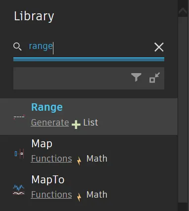
- Again, go to the search option and search for range and put it in the drawing screen
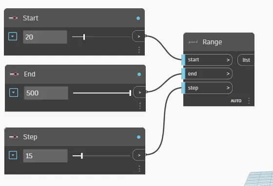
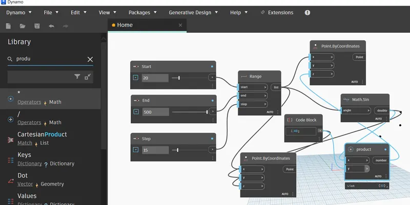
- Then connect to the integer slider to start, end and step as shown;
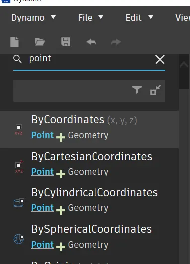
- Go to search library and search for "pointbycoordinates"
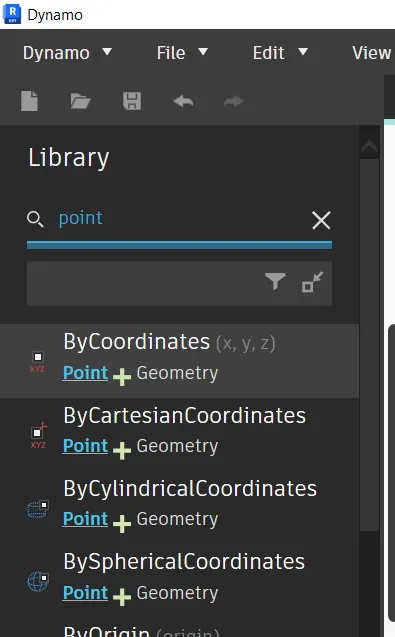
- Place the "pointbycoordinates" in the drawing screen
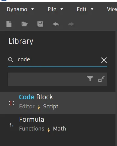
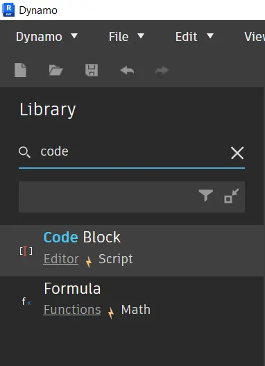
- Then go to the search again and search for "code block"
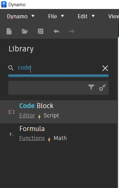
- Then copy the "pointbyco-ordinate" by using the copy and paste control commands
- Then search "math.sin" and invoke it to the screen
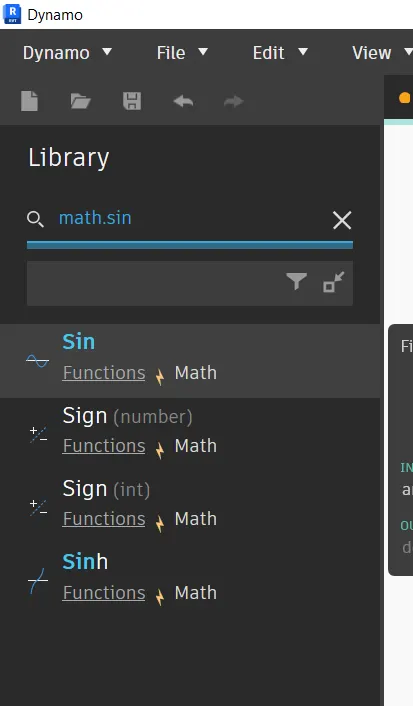
- connect the list from range to the x of point by coordinates
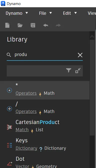
- And then connect the "range" to the "Math.sin"
- Search for "product" in the search
- Then connect the "code block" to the "pointbycoordinate"Z
- Connect the "Math.sin" to “pointsbyco-ordinate" y
- And also "code block" to "product" Y
- Now connect the "product" number to the "pointbycoordinates" Z
- Then connect to the "math.sin" to the "product"
- And also connect Range to the "pointbycoordinates" X
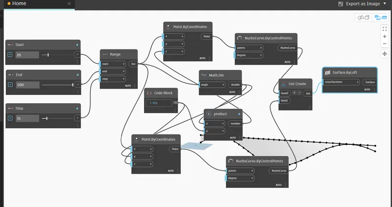
- Our model until now as below:
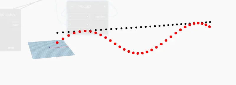
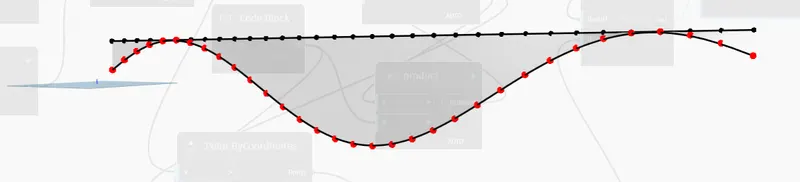
- FINALLY, sinusoidal curve has been formed
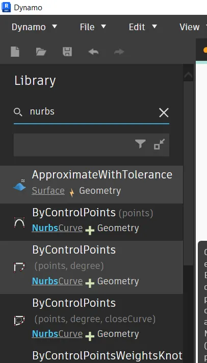
- Now go to search and search for "nurbsbycontrolpoint" OR nurbs
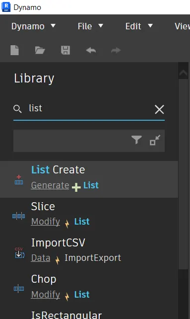
- Also search for List create and put it on the drawing screen
- Copy the nurbs by control point
- Connect the points by coordinates to the nurbs point
- And do the same for the other one also
- And we can see a line has been created in our curve
- Now go to create list and just add one more item on it
- Then connect the Nurb curve to the list create
- Then search for "surfacebyloft"
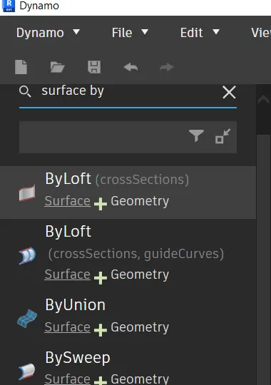
- Connect the list create to the "surfacebyloft"
- finally, surface has been created in our Sinosoudal curve
RESULT: - Using Dynamo, we have created a set of sinusoidal points and created a curve and created a surface out of the curve.
2) Create a conceptual layout of floor plan in dynamo. Using the tools available in dynamo link the lines to appropriate model elements in Revit by choosing the wall types and wall parameters. Make use of the sliders to slide through the height of the wall and length of the wall.
AIM: - To create a conceptual layout of floor plan in dynamo along with choose appropriate model elements such as wall types, wall parameters, height of the wall and length of the wall.
INTRODUCTION: - Creation of conceptual layout of floor plan in dynamo along with appropriate model elements such as wall types, wall parameters, height of the wall and length of the wall is going to be explained in detail with step-by-step procedure.
PROCEDURE: -
- Open Revit 2023.
- Go to Manage Tool.
- Open Dynamo in Visual programming.
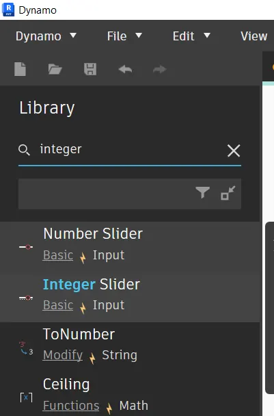
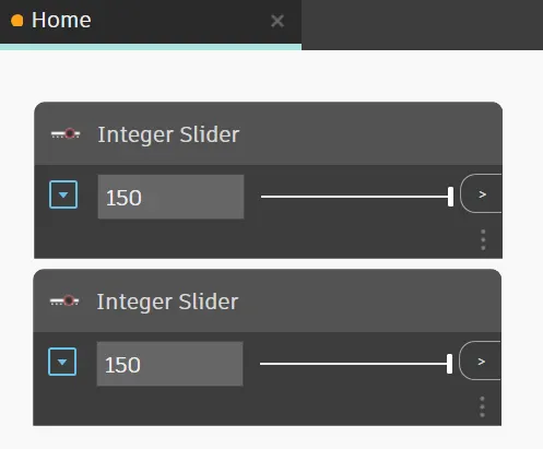
- Type integer in search box select "integer slider"
- Make 2 integer slider box
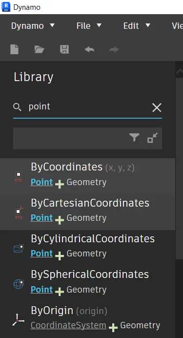
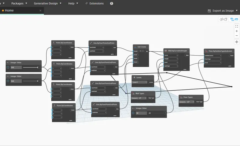
- Type "pointbycoordinate" in search to invoking it on the screen
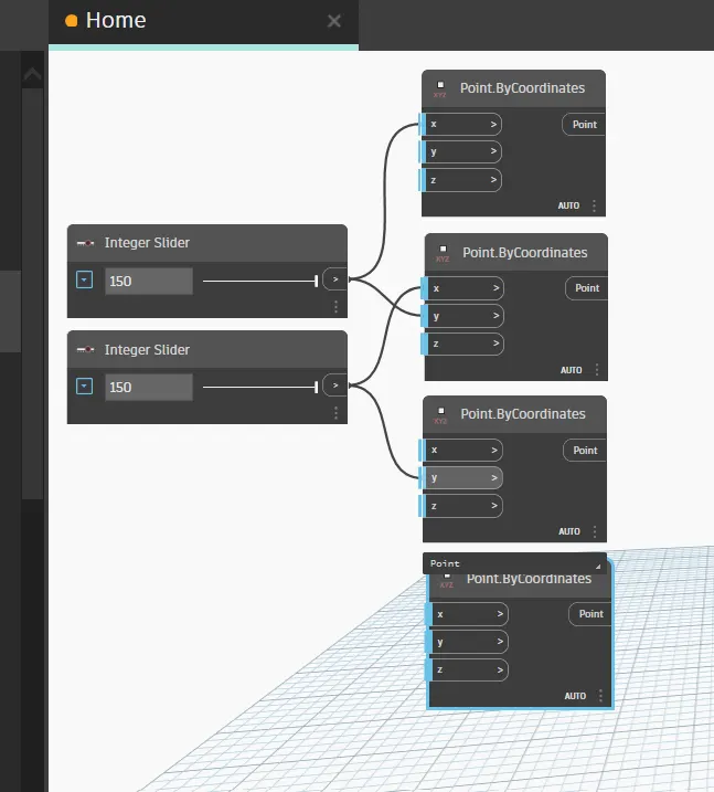
- Make 4 "pointbycoordinate"
- Connect integer slider 1 to X of point by coordinate 1
- Connect the integer slider 1 to Y of point by coordinate 2
- Connect the integer slider 2 to X of point by coordinate 2
- Connect the integer slider 2 to Y of point by coordinate 3
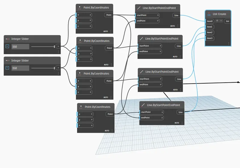
- Now we need to make lines
- Type line in search box and select line by start point and endpoint
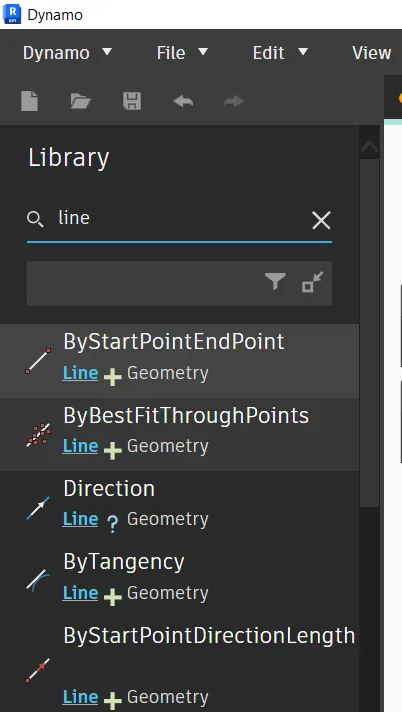
- Make 4 similar of it
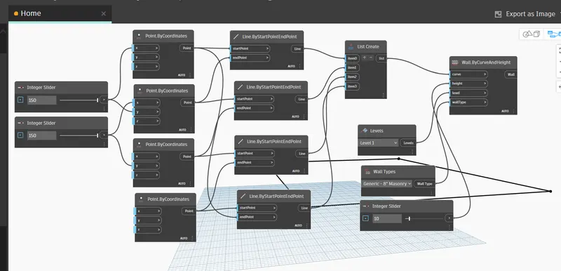
- And connect the point as shown in figure
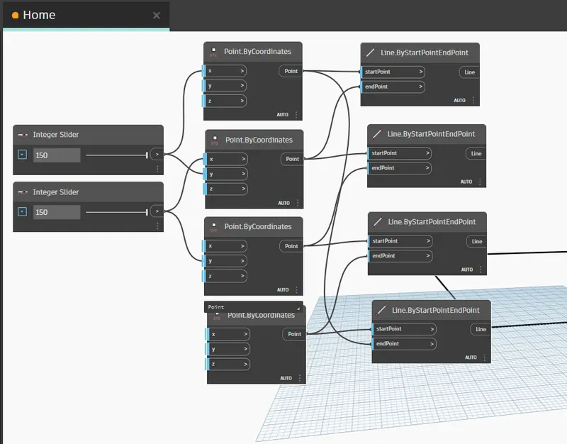
- drawn until the provided data
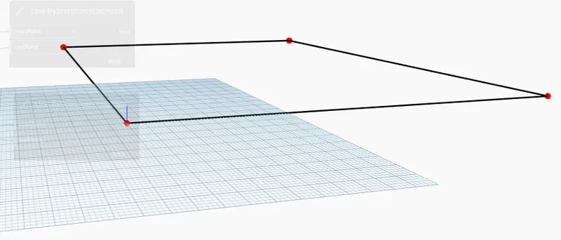
- Now we have to create wall height
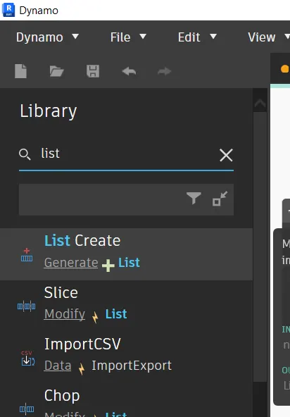
- Search list and select list create
- Connect the line of the line by start end point to the item 0, 1, 2 and 3
- Search option in search for walls
- Levels, wall types and also add integer slider
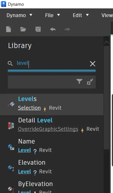
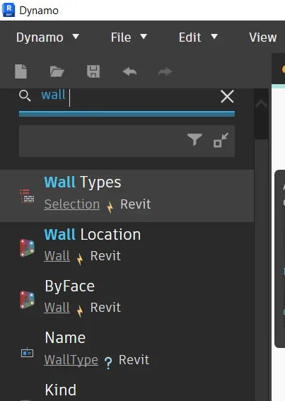
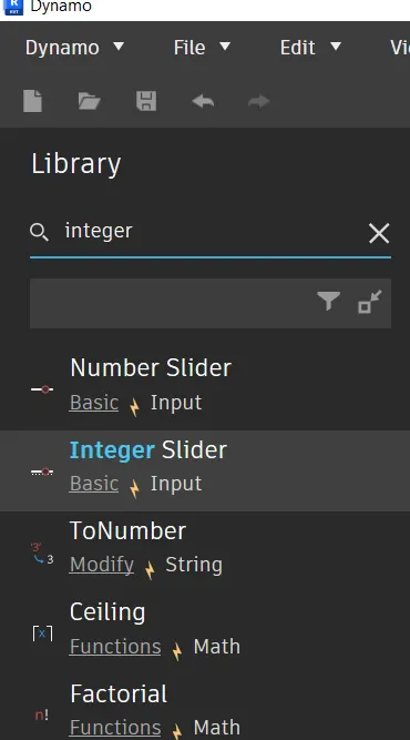
- Then connect the list, levels, wall types and integers slider to the wall by curve and height as per the name
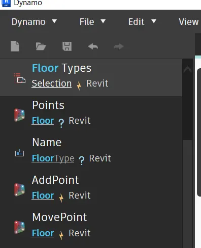
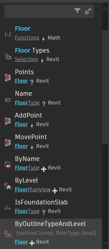
- then search for floor type then insert into drawing
- and byoutlinetypeandlevel for floor creation
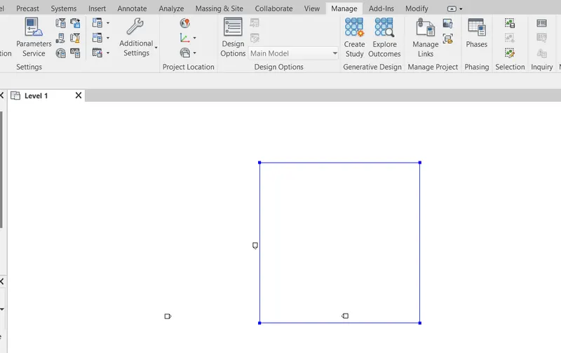
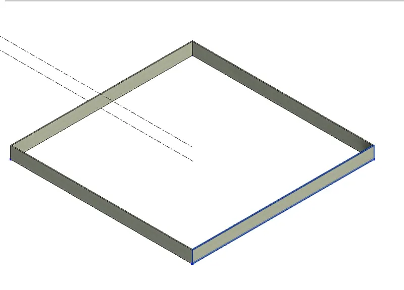
- The wall layout formed in Revit is as below;
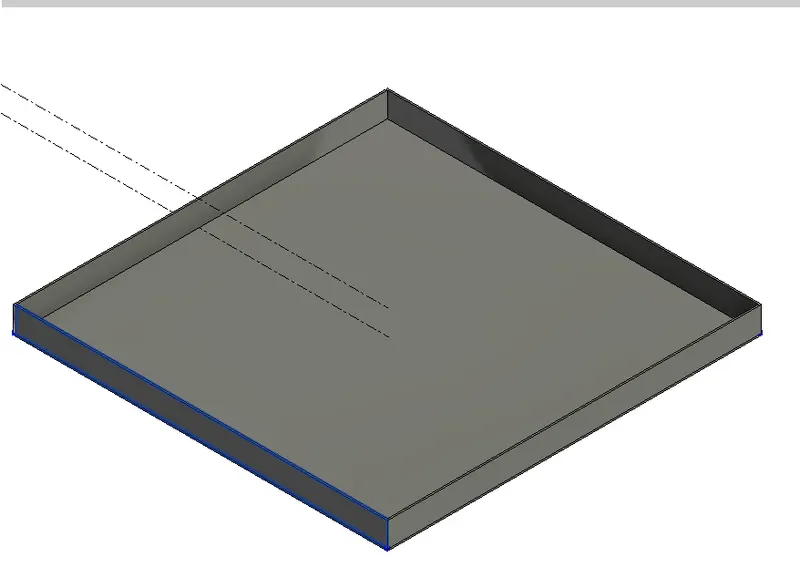
RESULT: - A conceptual layout of wall & floor plan is created by use of dynamo.
3) Create an array of model elements in Revit. Use dynamo to vary the properties of model elements by using the slider or code block
AIM: - Need to create an array of elements in Revit and vary the properties by using slider or code block in dynamo
INTRODUCTION: - Created the array of columns in Revit and by using the integer slider from dynamo, rotate the column in Revit
PROCEDURE: -
- Open Revit software
- In new architectural template
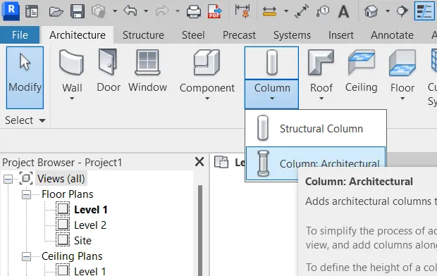
- Go to architecture and select architectural column
- Insert 4 columns as shown

- Go to manage tab, click on dynamo under visual programming
- Dynamo window will open
- Create a new dynamo model
- Search “Model Elements" and put it on the screen as below;
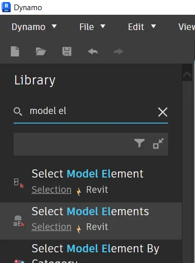
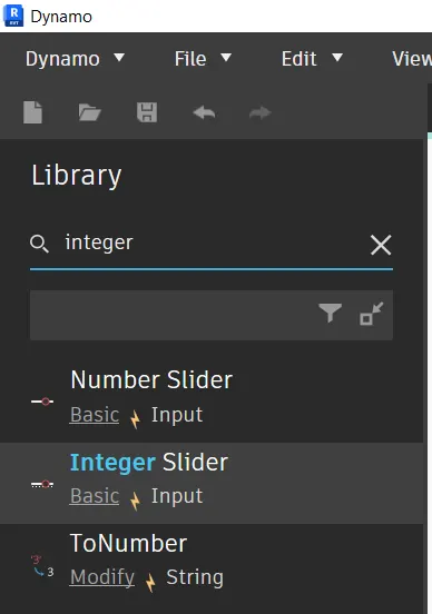
- Also, insert "Integer Slider" and provide the angle to the slider
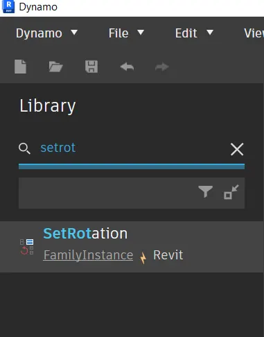
- Insert "FamilyInstance.SetRotation" and connect to Select Model Element and Integer Slider
- change the integer value (45 degree) which we will give as degree measurement for the rotation of the column
- the screen is as below up till;
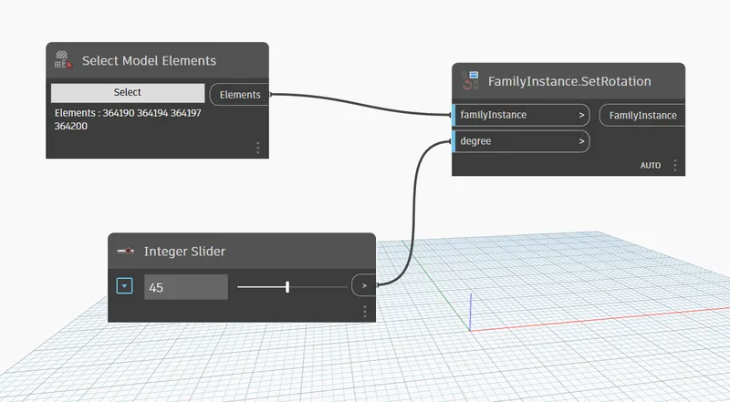
- select the columns in the Revit by clicking on select from select model element in the dynamo
- connect the "integer slider" to the degree of the "family instance"
- also connect the selected model element to the family instance as below;
- then the columns are rotated by 45 degrees in Revit module
RESULT: - After following above steps, obtain the result as shown below, column has been rotated by 45 degrees

4) Create a conceptual mass in Revit and develop a parametric column by dividing the surfaces and apply the concepts similar to use in parametric walkway modelling. Use triangular bent or square shaped panels to add finish to the parametric column
AIM: - Create the Conceptual Mass in Revit, create a form and use property of triangular bent icon in the parametric column
INTRODUCTION: - Created a Conceptual Mass and developed a parametric column by dividing the surface and finish the model by using triangular bent shape
PROCEDURE: -
- Open Revit 2023 in computer
- Go to File tab - from new select Conceptual Mass
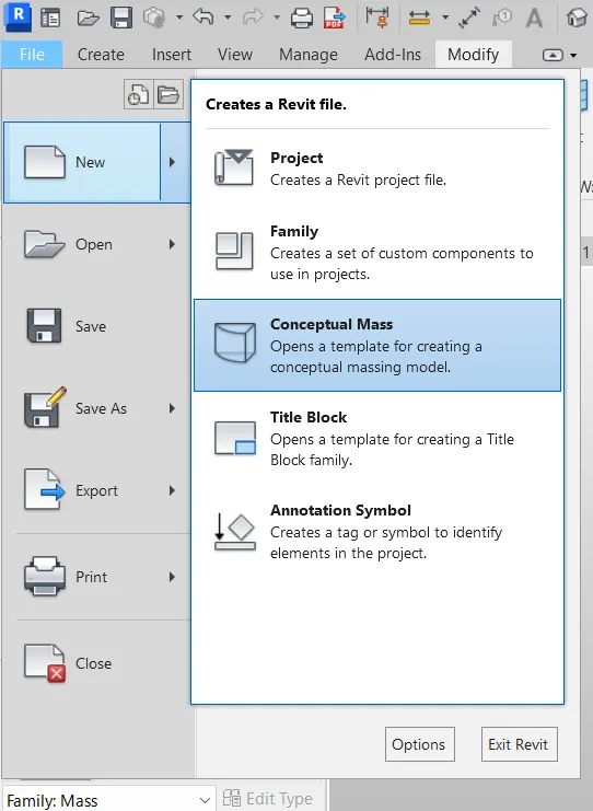
- Select Metric Mass from Conceptual Mass folder and click on open
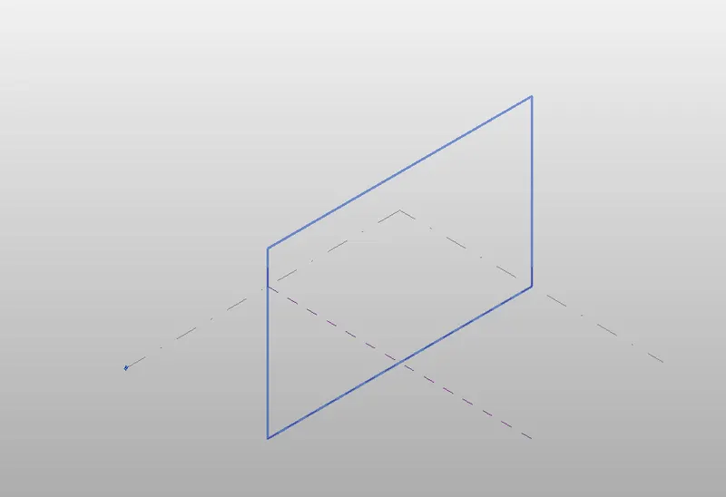
- screen is appeared like this;
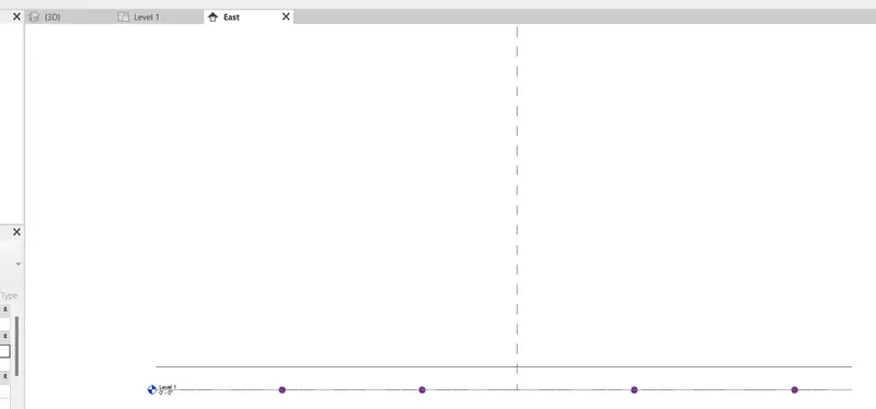
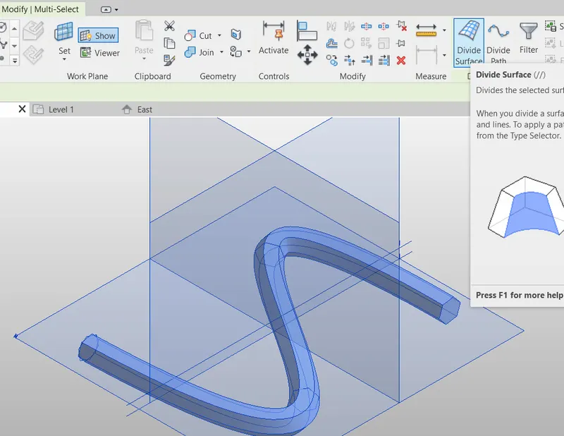
- Then select the spline through points option to draw the spline
- And draw the spline
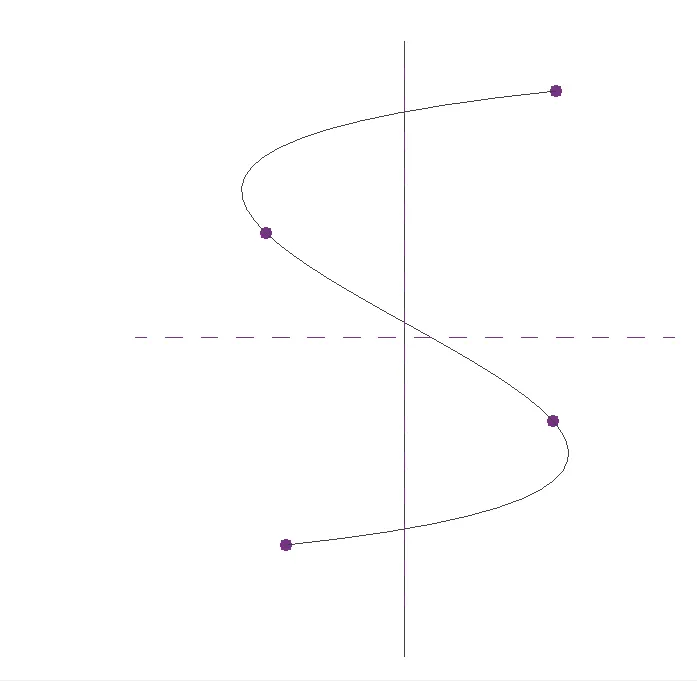
- After drawing the spline go to the modified tab where you will find a set work plane option
- Click on that option which is highlighted below;
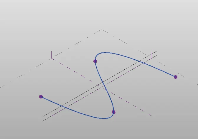
- Then draw the work plane by clicking on the set plane option and to view the plane just click on the show option
- Now to create the polygon around the spline just click on the circumscribed polygon option and draw the polygons on the spline and draw the polygons on the created work plane
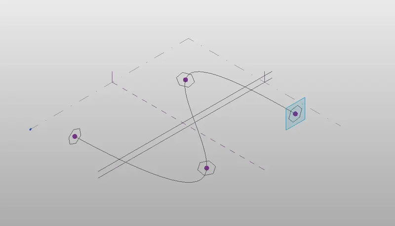
- After that select the created spline and all the polygons that we have created and go to the create form option and click on the solid form to create the solid form
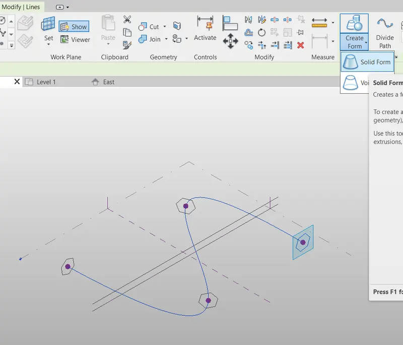
- Hence solid form has been created
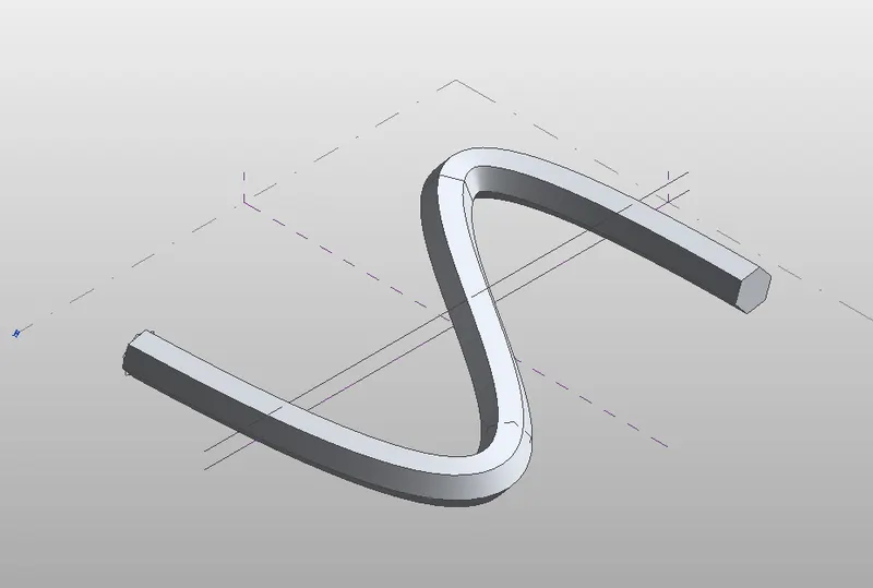
- Select the solid form
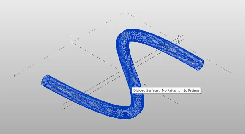
- Then go to the divide surface option
- After selecting the form change the property of pattern and number of U & V grid
- Select the pattern Triangle checkboard (flat)
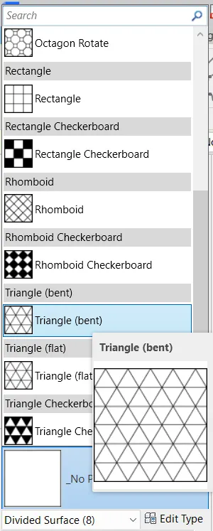
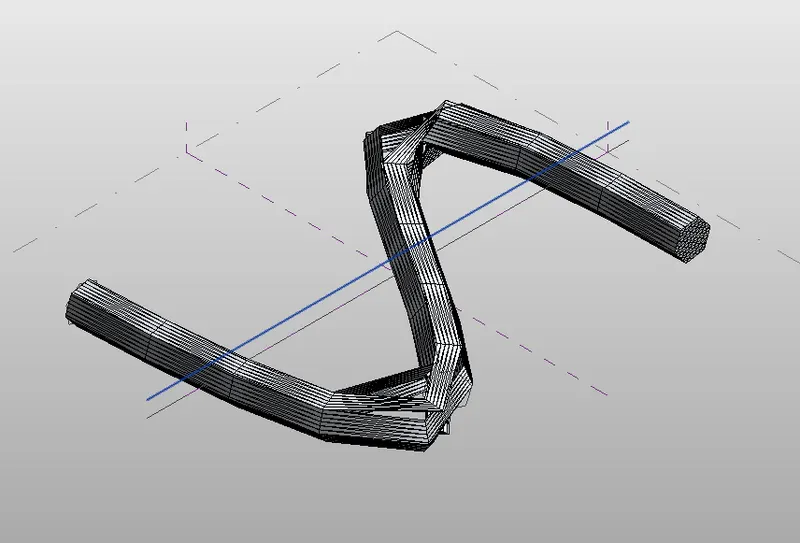
RESULT: - After following above steps, got the below shown result Conceptual Mass of parametric column and finished the model by using triangular bent shape
5) Use Dynamo to work on developing a Parametric Stadium. List your parameters and use the visual programming approach to complete the modelling, you can use the concepts discussed in parametric high-rise tower in class for reference.
AIM: - By using dynamo created conceptual wall layout of floor plan
INTRODUCTION: - To create the conceptual layout of a floor plan in dynamo, used available tool for joining the line, wall type and floor type and used sliders for height and length of wall
PROCEDURE: -
- Open Revit 2023.
- Go to Manage Tool.
- Open Dynamo in Visual programming.
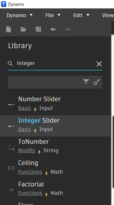
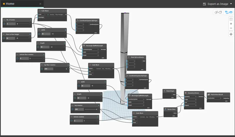
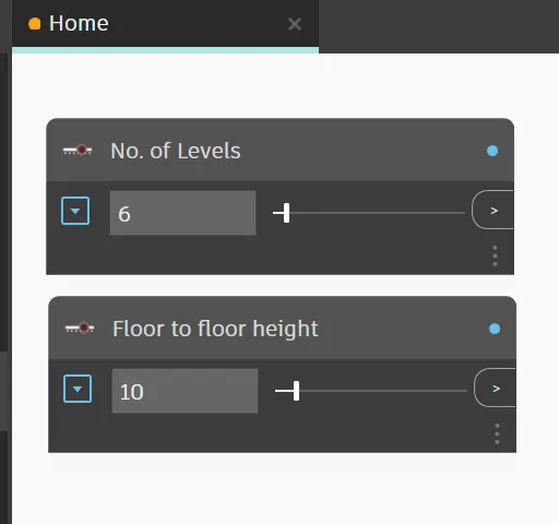
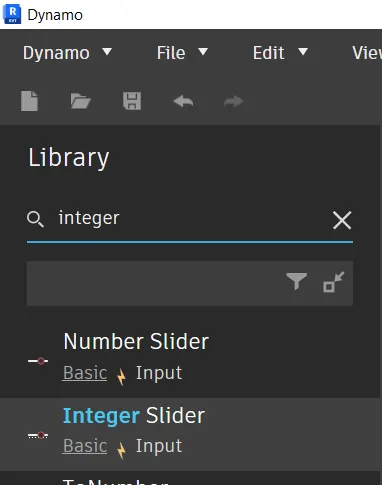
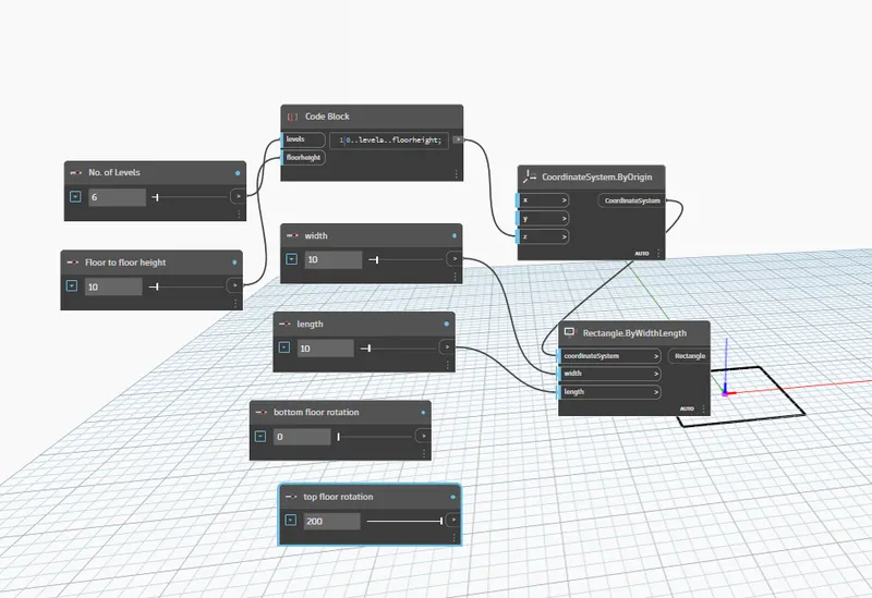
- Insert 4 Integer Slider and rename it i.e., Levels, Height, Top floor Rotation, Bottom floor Rotation.
- and assign the values to all integer sliders as shown below;
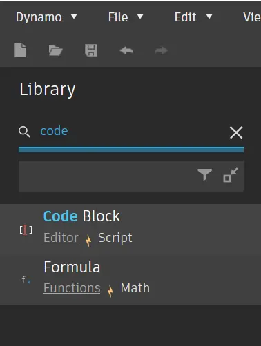
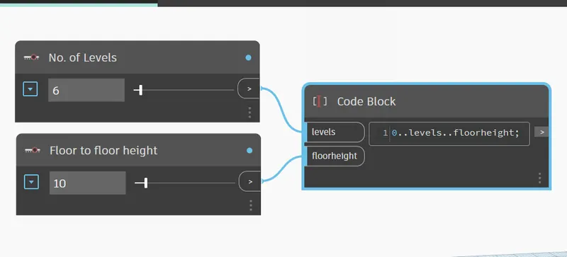
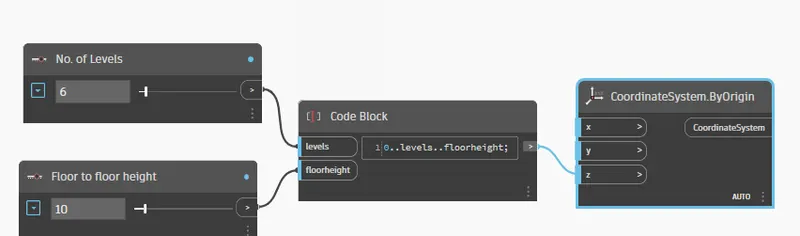
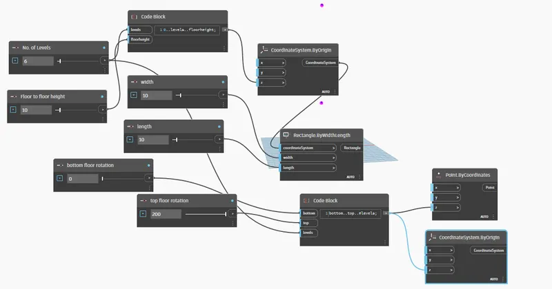
- Insert "Code Block" and provide code as “0. #Levels...FloorHeight”
- joint "number of levels " and "floor to floor height "to code block as shown;
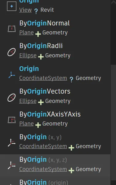
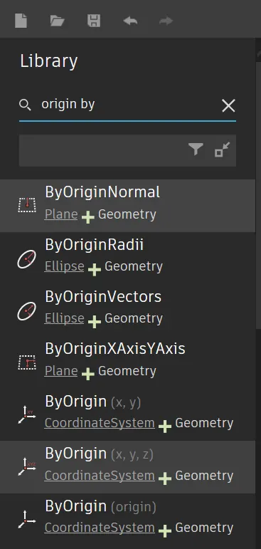
- Insert "CoordinateSystem.ByOrigin"
- Provide the output of code block as an input to z point of "CoordinateSystem.ByOrigin"
- This will show level points on z axis
- Insert 2 Integer Slider and renamed with Width and Length
- give them values as we are giving length as 30 and width as 25
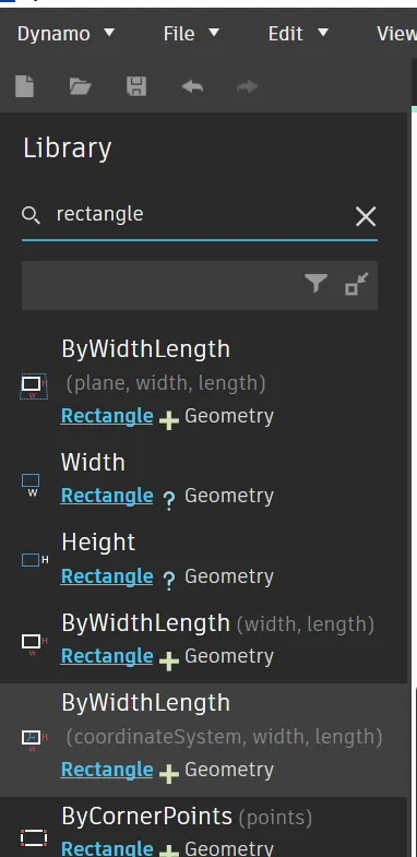
- Insert "Rectangle.ByWidthLength"
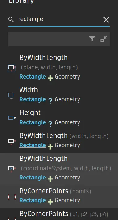
- connect width, length and "coordinatesystembyorigin " to "Rectangle.ByWidthLength"
- It obtains the rectangle on the z axis level
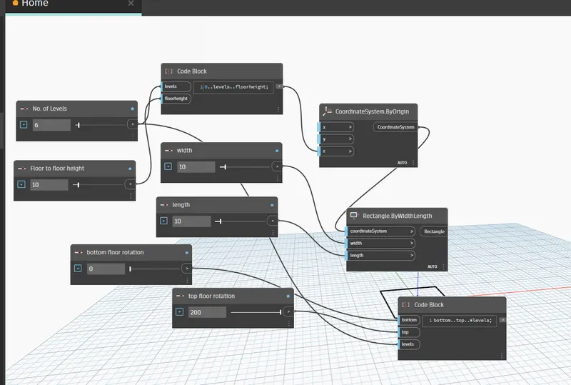
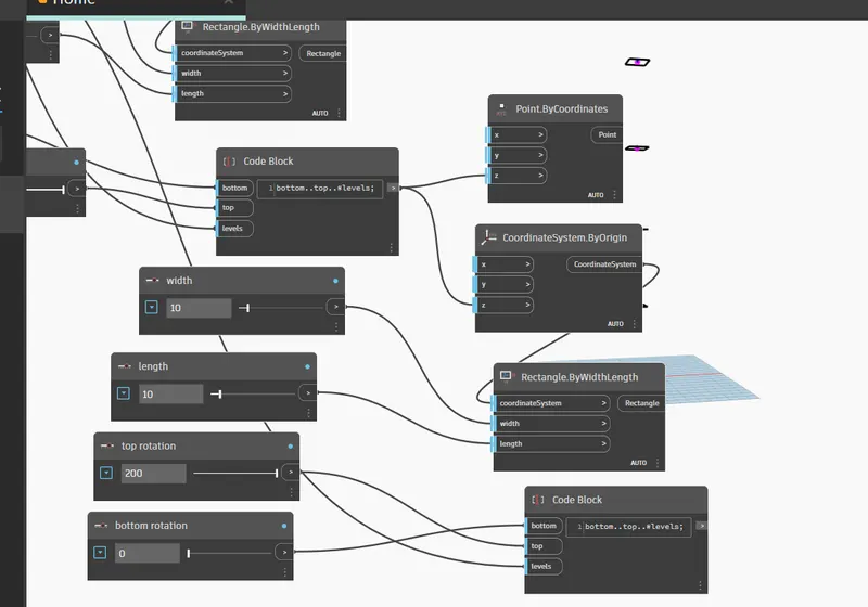
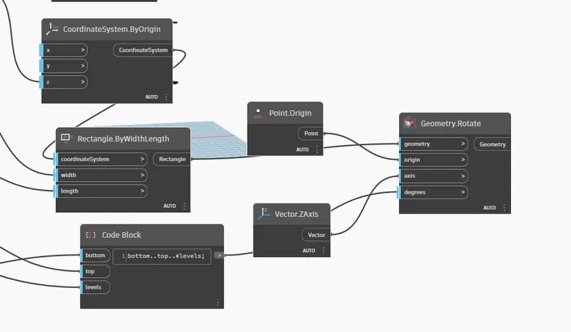
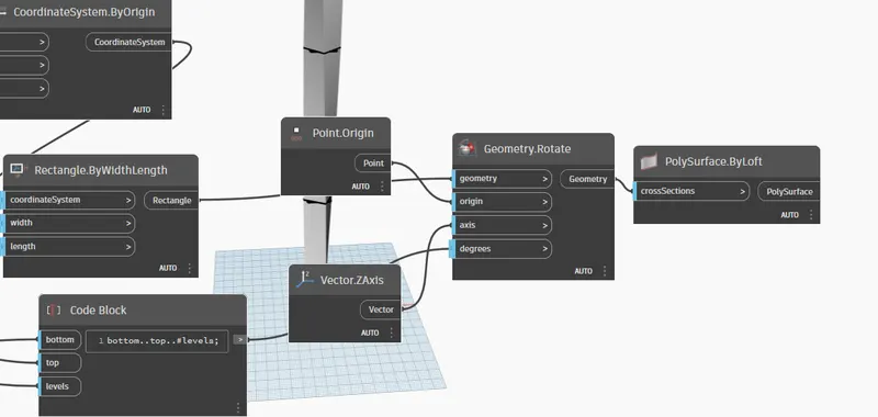
- put the "Code Block" and provide the code as “Bottom..Top..#Levels”
- Connect the code Block with Bottom floor Rotation, Top floor Rotation and Levels
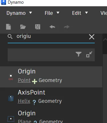
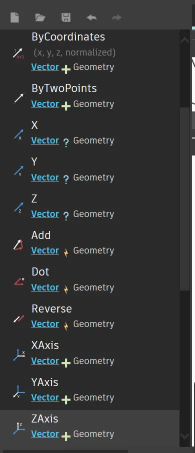
- Insert "Point.Origin" and "Vector.ZAxis"
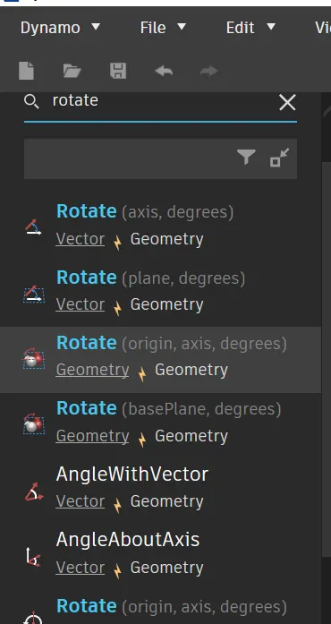
- Insert "Geometry.Rotate" and connect the boxes as below:
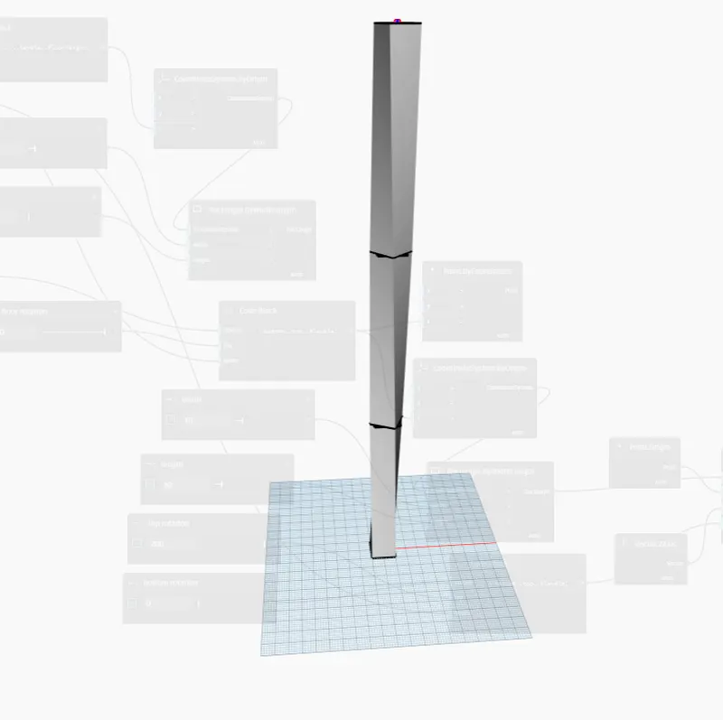
- The model until now is as below:
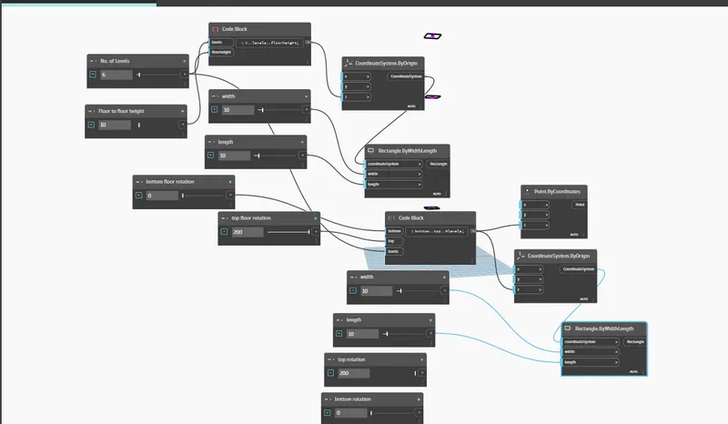
- insert code block and connect the respective way
- now insert origin point, Z Axis & rotate geometry for the drawing
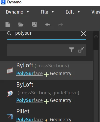
- Insert "PolySurface.Byloft"
- connect the "geometry.rotate" to the "PolySurface.Byloft"
RESULT: - by Using Dynamo develooped a Parametric Stadium. Listed your parameters and used the visual programming approach to complete the modelling.