Creating Conceptual mass in REVIT and Creation of Sinusoidal curve and a Parametric stadium using Dynamo
Question 1) Using Dynamo create a set of sinusoidal points and create a curve and create a surface out of the curve.
AIM: Using dynamo create a set of sinusoidal points and create a curve and create a surface out of the curve.
INTRODUCTION: Dynamo is a visual programming software. Now a days we are in need of the dynamo because in the construction industry or we can say that the project oriented industries are fastly moving towards the artificial intelligence or we can say that they are moving towards the machine learning.Dynamo also enhance the project process and work flow.Now a days people are leaning towards the dynamo in order to improve their work process and enhances the project process. It is a visual programming tool that helps in expressions we can arrange graphics,texts,as a part of its syntex secondary notation.Inspite of creating the programme textually, this programming language it allows the user to manupulate the graphical elements in the interactive manner.In dynamo we eill be laerning about the certain keywords like wire,nodes,input,output etc, and we will be laerning these such as wire,node in order to achieve the purpose that we are looking for.So here we will be learning about how to create a set of sinusoidal points and using those points haw can we create the curve and after creating the curve we will be creating the surface using the same sinusoidal points and curve in a very detailed manner.All the detailed process has been discussed below:
PROCEDURE:
- First of all go to the revit software open that software.
- And then create the new template using the New option in the home page of the revit.
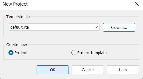
- Now create a imperial template,go to the browse option there search of the English-imperial option and then click on the option default and then option OK.
- Now our imperial template have been created as shown in the below figure:
- Now go to the Manage toolbar there is an option called Dynamo,click on that option as shown in the below image:

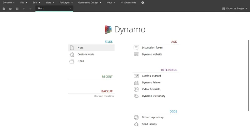
- Now the Dynamo home page opens, in that home page there is an option called New just click on that option as shown in the below image:
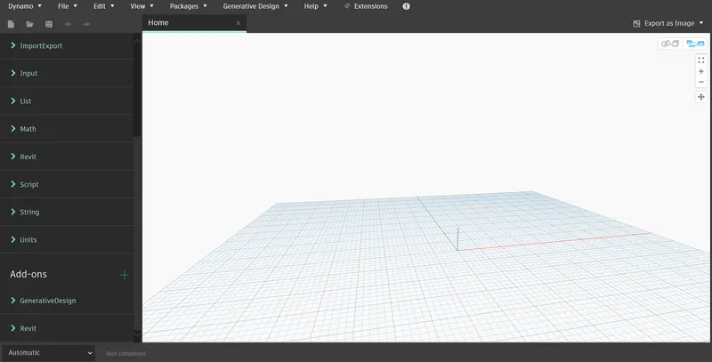
- A new workspace or we can say that a new file opens as shown in the below image:
(A) SINUSOIDAL POINTS:
- First of all we will be creating the sinusoidal points using the dynamo software.
- So in order to create the sinusoidal points,first we need to go to the search bar which is present at the left side of the screen.
- From there there is a box at the left side in that box there is an option called search,so go to that search tab and just write Integer and there are multiple options regarding integars as shown in the below image:
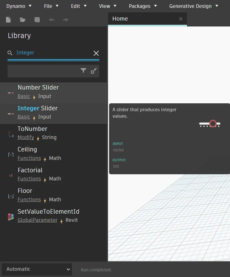
- So in that we have to go with the Integer Slider option just click on that option. A box with the name Integer slider appears on the workplace but we want three of integer slider so simply select the integer slider and copy that slider in order to copy that slider just press "Ctrl+C" and then paste it using the shortcut key "Ctrl+V" now the another integral slider appears on the screen just as shown in the below figure:
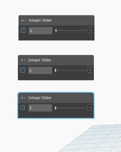
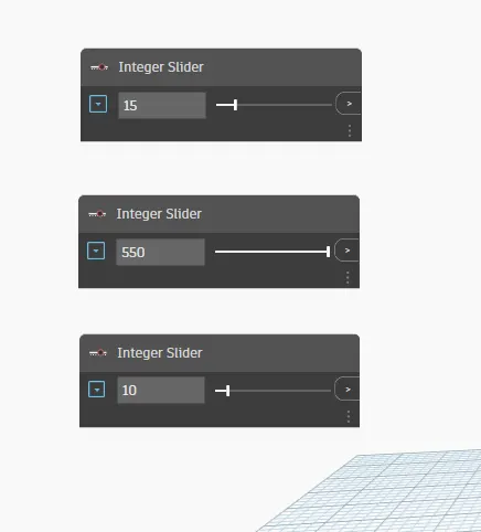
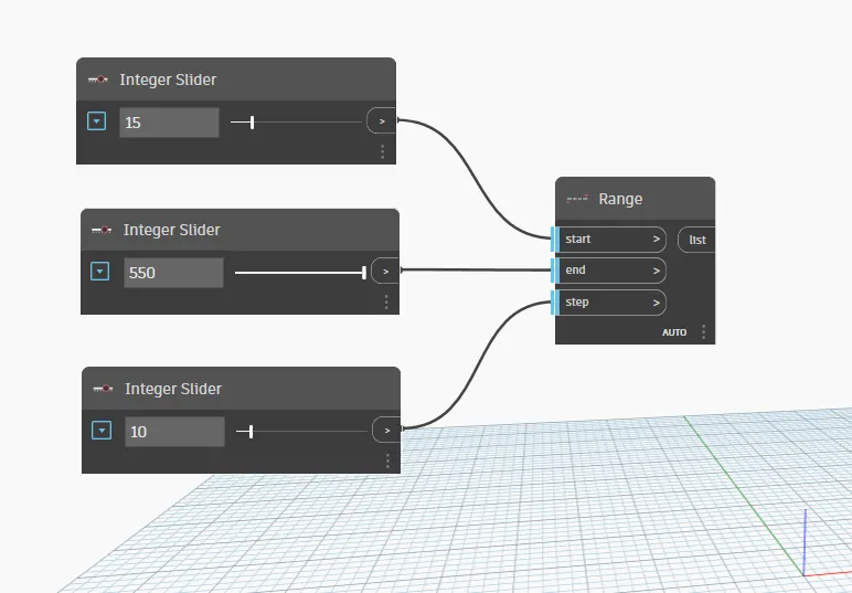
- Now we have to give some numbers to that integar slider,so lets assume:
Integar slider 1: 15
Integar slider 2: 550
Integar slider 3: 10
- As shown in the below image:
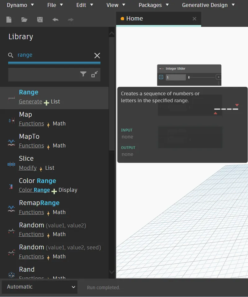
- We have to go to the search bar again,there type range, there are many option related to the range just click on the option Range as shown in the below figure:
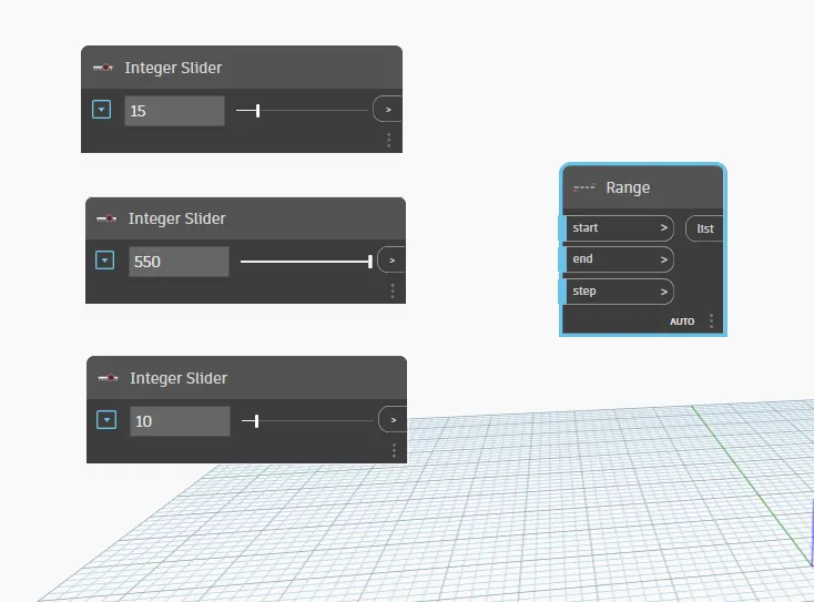
- After doing this a new box of Region appears on the screen as shown in the below figure:
- And now we have to connect the three integer slide with the Range.
- And to connect these two boxes we will be using nodes to connect them.
- In the box Range we have three elements called Start,End and Step.
- So we will be connecting the first integer slider with the Start option of the Range box, and then again we will be connecting the second integer slider with the same Range box but this time with the another element named End from the Range box and the third integar slider with the same Range box but this time also with the different element named as Step as shown in the below figure:
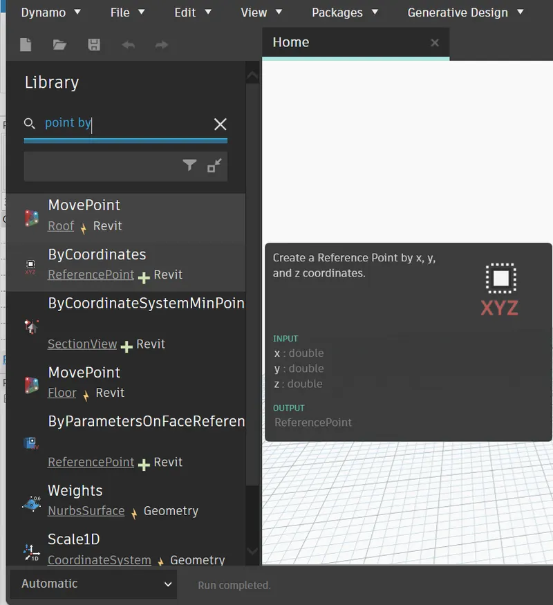
- After that we have to go to the search bar again from there we have to search for the Points by co-ordinates as shown in the below figure:
- So just click that option and we will be able to get the Reference point by co-ordinates box on the screen as shown in the below figure:
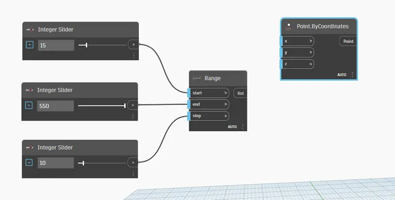
- And now we have to connect the Range box with the Refrence point by co-ordination.
- And to connect these two boxes we will be using nodes to connect them.
- In the box ReferencePoint.ByCo-ordinate we have three co-ordinates called x,y,z.
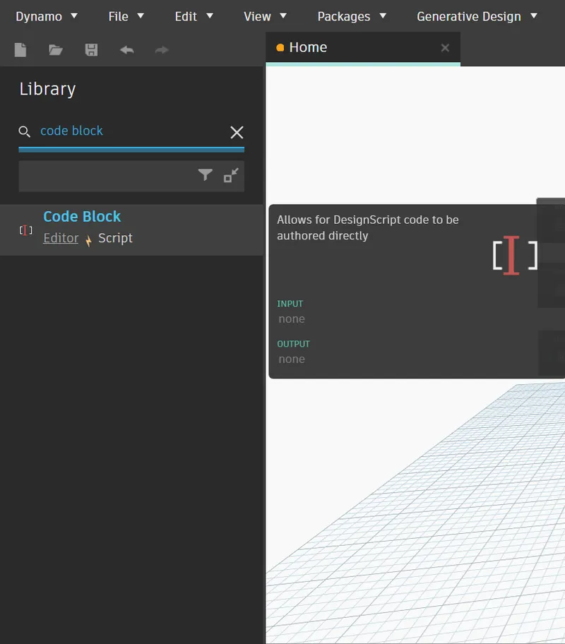
- After this we will be going to the search bar once again,from there search Code block and there is an option called code block just click on that as shown in the below figure:
- After doing this a new box of Region appears on the screen as shown in the below figure:
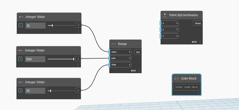
- Now we need 1 more boxe in order to complete the connections so what we will be doing is just we have to copy that box and paste it 1 more times in the workspace. So in order to do that copy and paste we just need to select the Point.ByCordinates and copy that box in order to copy that just press "Ctrl+C" and then paste it using the shortcut key "Ctrl+V" now the another Point.ByCordinates appears on the screen just as shown in the below figure:
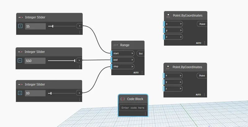
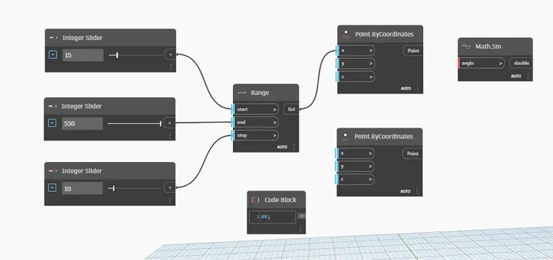
- So we will be connecting the Range box with the x value of the Refrence point by co-ordination box and give the code block as 60 as shown in the below figure:
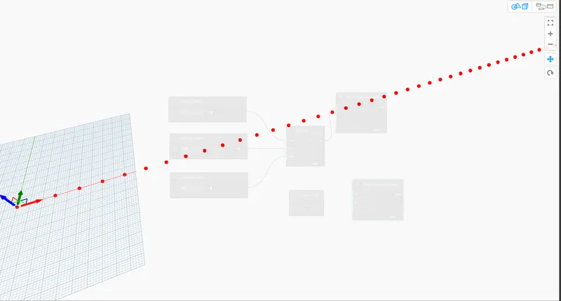
- After doing this we will be seen that the points have been created as shown in the below figure:
- After this again go to the search bar, from that bar just type Math.sin and then there is an option called Sin just click on that option as shown in the below figure:
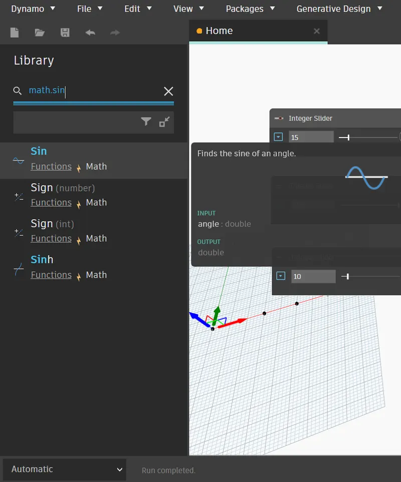
- After doing this a new box of Math.sin appears on the screen as shown in the below figure:
- Go to the search bar, from that bar just type product and then there is an option called * just click on that option as shown in the below figure:
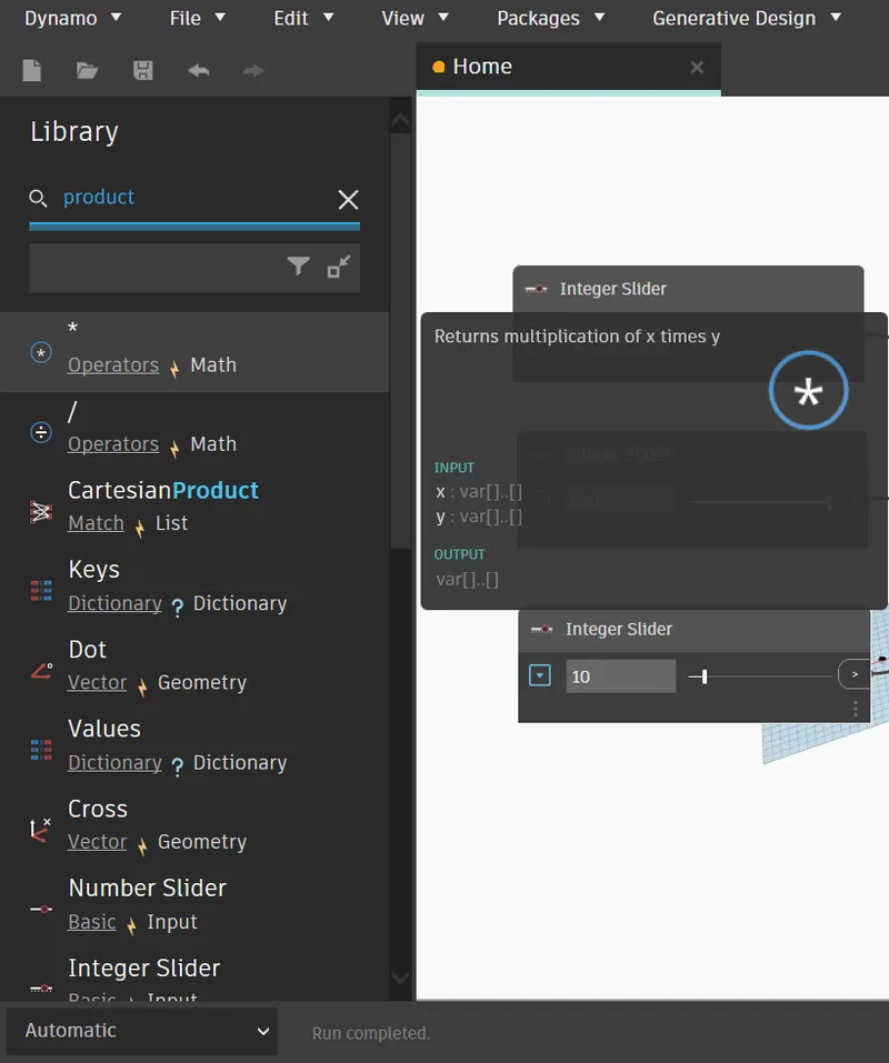
- After doing this a new box of * appears on the screen as shown in the below figure:
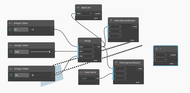
- After this we will be doing the connections.
- For doing the connections,connect the Range Inst with the Math.sin again connect the Range Inst with the first box of Points.ByCoordinates x value and again connect the Range Inst with the second box of the Point.ByCoordinates x value.
- Now connect the Code block with the y value of the Points.ByCoordinates as shown in the below figure:
- After doing these connections we will be seeing another sets of points as shown in the below figure:
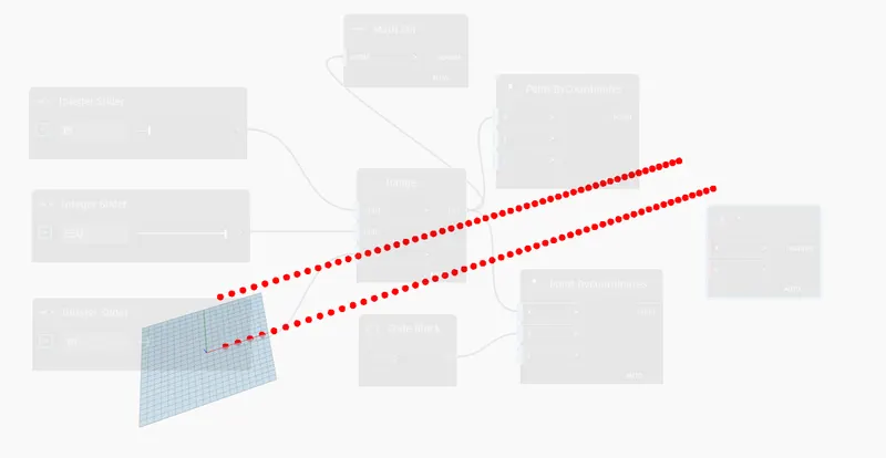
- Now the sinusoidal points have been created as shown in the above figure.
(B) Sinusoidal Curve:
- In order to create the sinosuidal curve we need to go to the search bar, from that bar just type Math.sin and then there is an option called Sin just click on that option as shown in the below figure:
- After doing this a new box of Math.sin appears on the screen as shown in the below figure:
- Go to the search bar, from that bar just type product and then there is an option called * just click on that option as shown in the below figure:
- After doing this a new box of * appears on the screen as shown in the below figure:
- Now we will be doing the connections,
- First of all connect the Code block with the z value of the second box of the Points.ByCoordinates and then connect the code block again with the * box with the y value and connect the Math.sin box with the Range Inst as shown in the below figure:
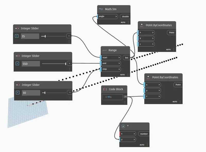
- After this connect the Math.sin with the x value of the * box as shown in the below figure:
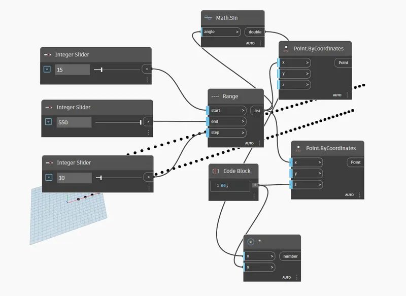
- After this connect the * box number with the z value of first box of the Points.ByCoordinates as shown in the below figure:
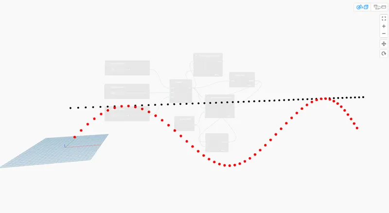
- A curve have been created as shown in the above figure.
(C) TO CREATE A SURFACE OUT OF THE CURVE:
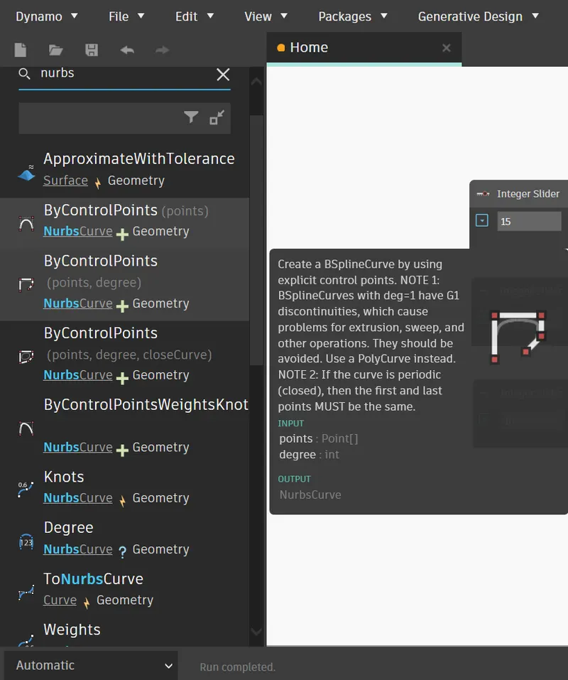
- For creating a surface out of the curve we need to go to the search bar, from that bar just type Nurbs and then there is an option called NurbsCurve.ByControlPoints just click on that option as shown in the below figure:
- After doing this a new box of NurbsCurve.ByControlPoints appears on the screen as shown in the below figure:
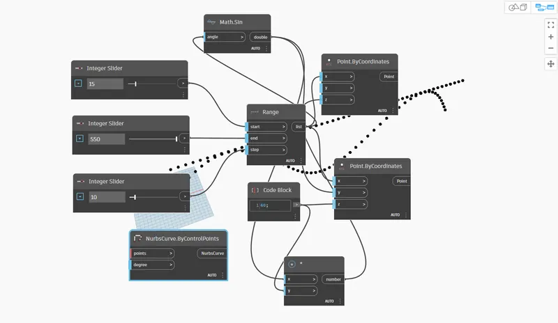
- Again go to the search bar, from that bar just type List and then there is an option called List Create just click on that option as shown in the below figure:
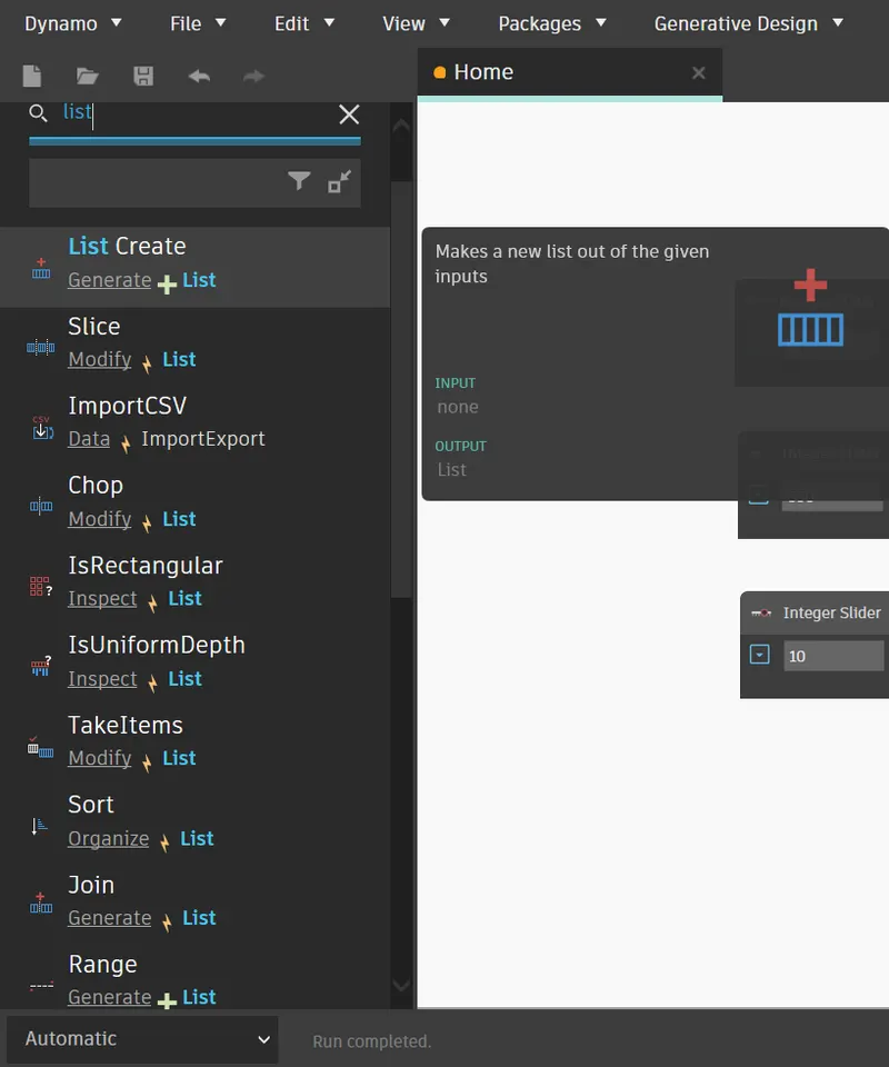
- After doing this a new box of List create appears on the screen as shown in the below figure:
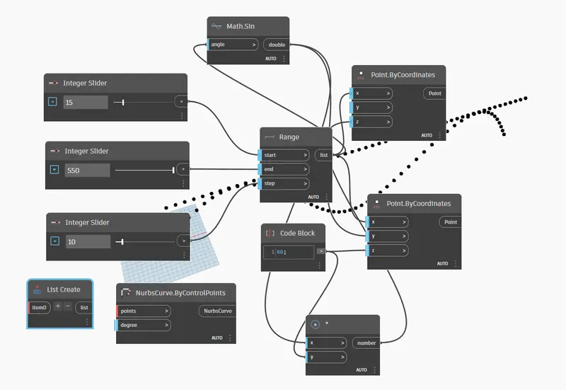
- Again go to the search bar, from that bar just type surface by and then there is an option called By Loft just click on that option as shown in the below figure:
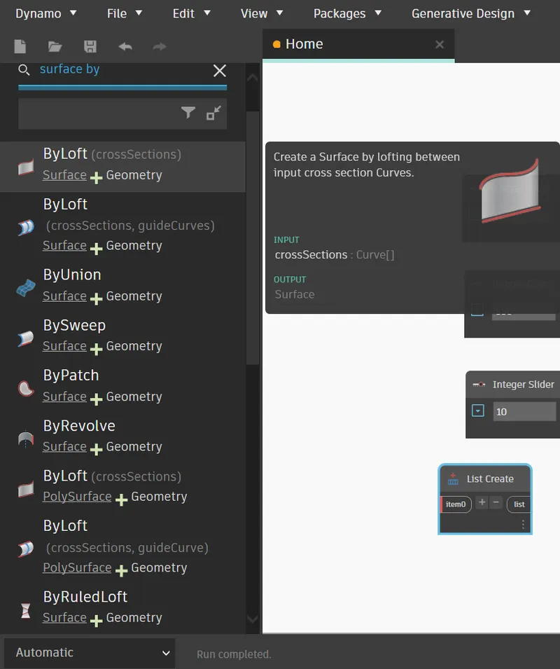
- After doing this a new box of Surface by loft appears on the screen as shown in the below figure:
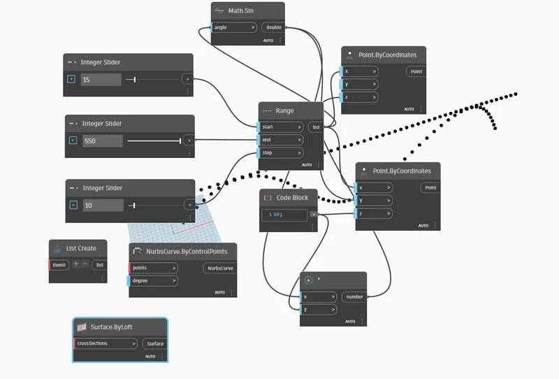
- Now we will be doing the connections.
- Connect the NurbsCurve.ByControlPoints point to the Points.ByCoordinates point.
- Connect NurbsCurve.ByControlPoints to the Item o of the List create box.
- Connect Item 1 of the list create box with the Second box of the NurbsCurve.ByControlPoints.
- Now connect the Surface.ByLoft to the List create(list).
- And connect *(number) to the second box of the NurbsCurve.ByControlPoints as shown in the below figure:
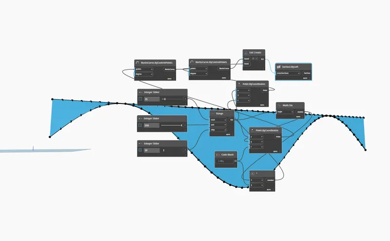
- The curve have been created as shown in the below figure:
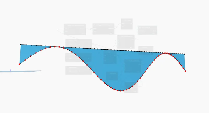
FINAL RESULT:
(A) SINUSOIDAL POINTS:
Connection made using the Dynamo:
And the final result:
- Now the sinusoidal points have been created as shown in the above figure.
(B) SINUSOIDAL CURVE:
Connection made using the Dynamo:
And the final result:
(C) TO CREATE A SURFACE OUT OF THE CURVE:
Connection made using the Dynamo:
And the result:
Question 2) Create a conceptual layout of floor plan in dynamo . Using the tools available in dynamo link the lines to appropriate model elements in Revit by choosing the wall types and wall parameters. Make use of the sliders to slide through the height of the wall and length of the wall.
AIM: Using dynamo create a conceptual layout of floor plan in dynamo . Using the tools available in dynamo link the lines to appropriate model elements in Revit by choosing the wall types and wall parameters. Make use of the sliders to slide through the height of the wall and length of the wall.
INTRODUCTION: Dynamo is a visual programming software. Now a days we are in need of the dynamo because in the construction industry or we can say that the project oriented industries are fastly moving towards the artificial intelligence or we can say that they are moving towards the machine learning.Dynamo also enhance the project process and work flow.Now a days people are leaning towards the dynamo in order to improve their work process and enhances the project process. It is a visual programming tool that helps in expressions we can arrange graphics,texts,as a part of its syntex secondary notation.Inspite of creating the programme textually, this programming language it allows the user to manupulate the graphical elements in the interactive manner.In dynamo we eill be laerning about the certain keywords like wire,nodes,input,output etc, and we will be laerning these such as wire,node in order to achieve the purpose that we are looking for.So here we will be learning about how to create a set of sinusoidal points and using those points haw can we create the curve and after creating the curve we will be creating the surface using the same sinusoidal points and curve in a very detailed manner.All the detailed process has been discussed below:
PROCEDURE:
- First of all go to the revit software open that software.
- And then create the new template using the New option in the home page of the revit.
- Now create a imperial template,go to the browse option there search of the English-imperial option and then click on the option default and then option OK.
- Now our imperial template have been created as shown in the below figure:
- Now go to the Manage toolbar there is an option called Dynamo,click on that option as shown in the below image:
- Now the Dynamo home page opens, in that home page there is an option called New just click on that option as shown in the below image:
- A new workspace or we can say that a new file opens as shown in the below image:
- From there there is a box at the left side in that box there is an option called search,so go to that search tab and just write Integer and there are multiple options regarding integars as shown in the below image:
- So in that we have to go with the Integer Slider option just click on that option. A box with the name Integer slider appears on the workplace but we want two of integer slider so simply select the integer slider and copt that slider in order to copy that slider just press "Ctrl+C" and then paste it using the shortcut key "Ctrl+V" now the another integral slider appears on the screen just as shown in the below figure:
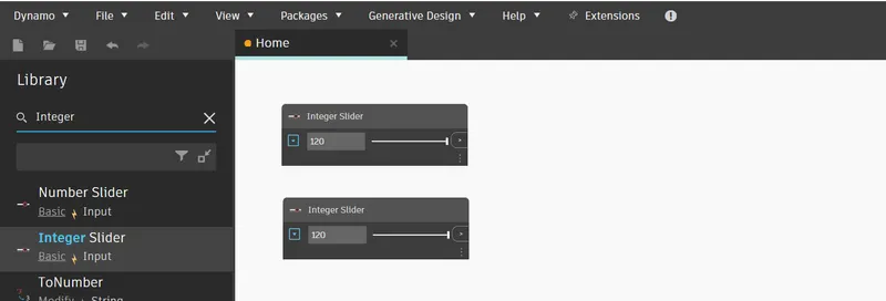
- Now select the integer sliders value as 120 for the first integer slider and the 120 again for the second integer slider.
- After that we have to go to the search bar again from there we have to search for the Points by co-ordinates as shown in the below figure:
- So just click that option and we will be able to get the Reference point by co-ordinates box on the screen as shown in the below figure:
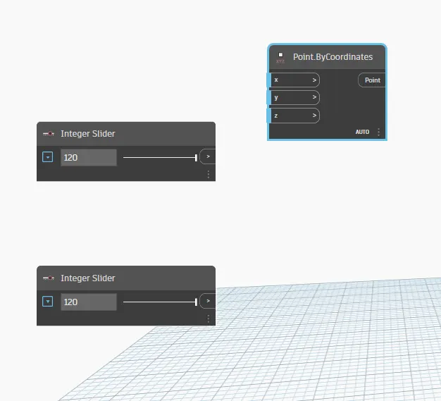
- But here we need 3 more boxes in order to complete the connections so what we will be doing is just we have to copy that box and paste it 3 more times in the workspace. So in order to do that copy and paste we just need to select the ReferencePoint.ByCoordinate and copt that box in order to copy that just press "Ctrl+C" and then paste it using the shortcut key "Ctrl+V" now the another ReferencePoint.ByCoordinate appears on the screen just as shown in the below figure:
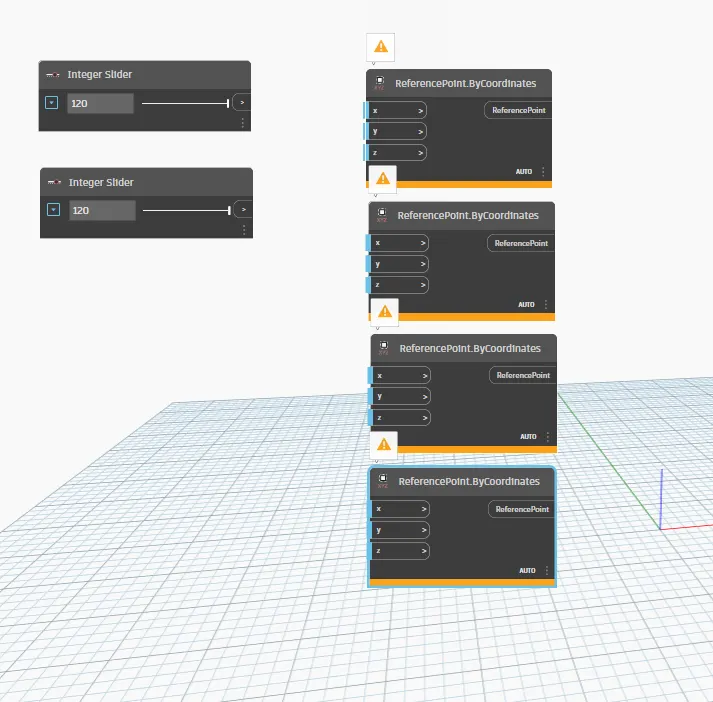
- And now we have to connect the integer slide with the Refrence point by co-ordination.
- And to connect these two boxes we will be using nodes to connect them.
- In the box ReferencePoint.ByCo-ordinate we have three co-ordinates called x,y,z.
- So we will be connecting the first integer slider with the x value of the Refrence point by co-ordination box, and then again we will be connecting the same integer slider with the same ReferencePoint.ByCo-ordination box but this time with the another value named y from the second Refrence point by co-ordination box as shown in the below figure:
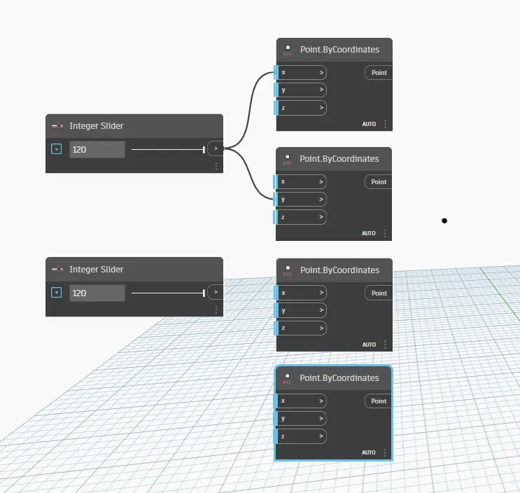
- Now we will be able to get the second point as we can see in the below figure:
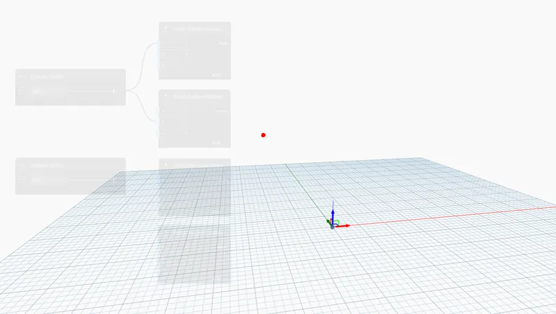
- And now similarly connect the second integar slider with the x value of the second Refrence point by co-ordination box, and then again we will be connecting the same integer slider with the third ReferencePoint.ByCo-ordination box but this time with the another value named y, just as shown in the below figure:
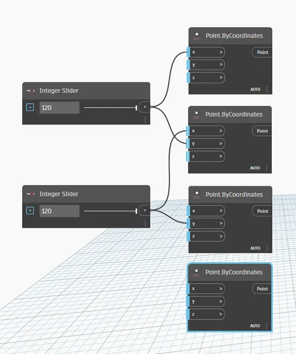
- Now after doing this, our third point have also been created as shown in the below figure:
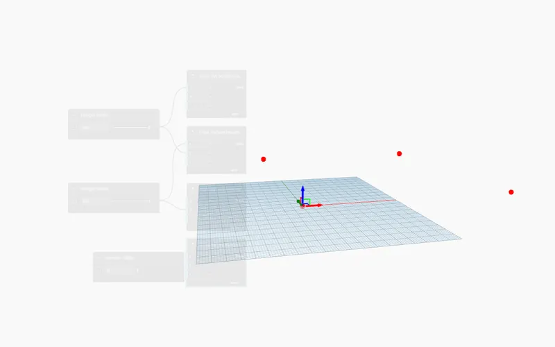
- This is how we will get our Four points in order to draw the wall. Now that the four points have been created as shown in the above figure,now we have to create the walls.
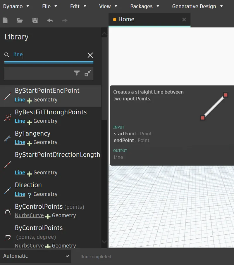
- For this we have to go to the search bar again,there type line, there are many option related to the line just click on the option ByStartPointEndPoint as shown in the below figure:
- After doing this a new box of ByStartPointEndPoint appears on the screen as shown in the below figure:
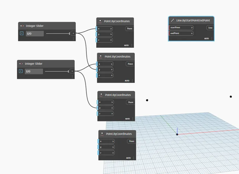
- Now we need 3 more boxes in order to complete the connections so what we will be doing is just we have to copy that box and paste it 3 more times in the workspace. So in order to do that copy and paste we just need to select the ByStartPointEndPoint and copy that box in order to copy that just press "Ctrl+C" and then paste it using the shortcut key "Ctrl+V" now the another ByStartPointEndPoint appears on the screen just as shown in the below figure:
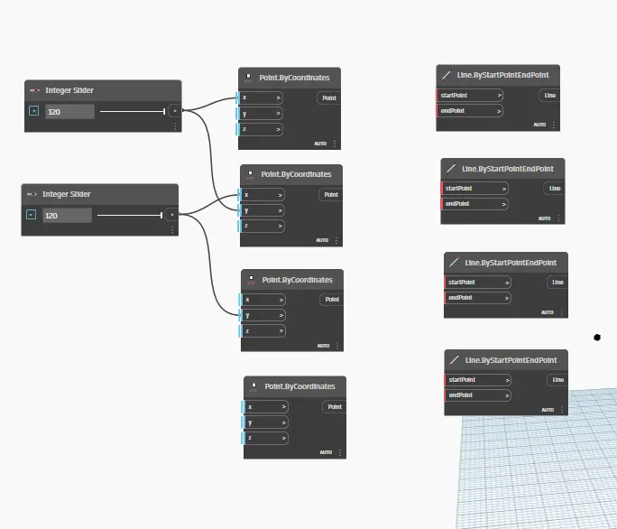
- After doing this we will be doing the connections.
- In the Line.ByStartPointEndPoint there are two elements called startpoint and the endpoint.
- So do the connections first connect the first box of PointByCoordinates box with the Startpoint of the first box of the Line.ByStartPointEndPoint box as shown in the below figure:
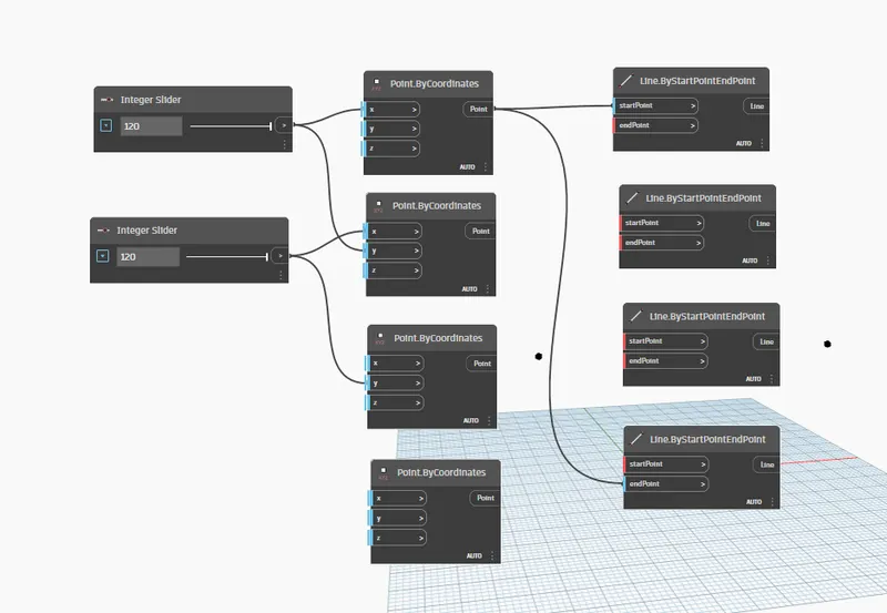
- Next connect the first second of PointByCoordinates box with the Endpoint of the first box of the Line.ByStartPointEndPoint box as shown in the below figure:
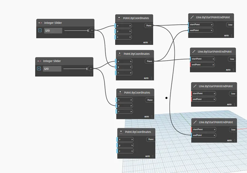
- After doing this connection we will be seeing our first line have been created as shown in the below figure:
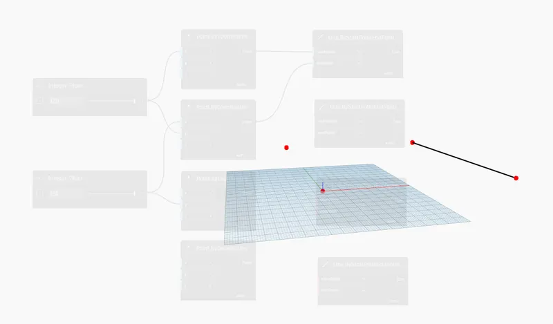
- Now connect the third box of PointByCoordinates box with the Endpoint of the second box of the Line.ByStartPointEndPoint box as shown in the below figure:
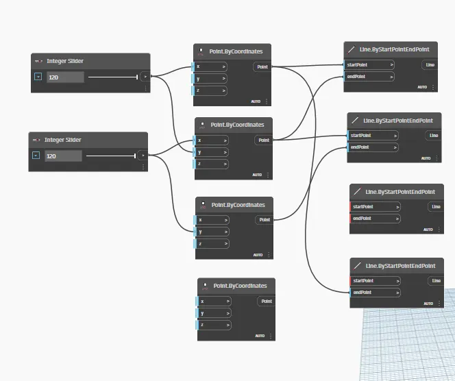
- The second line also have been created as shown in the below figure:
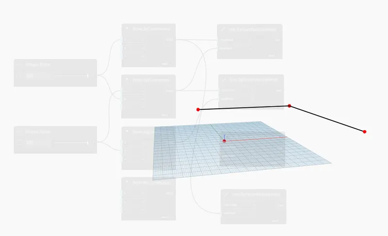
- Similarly,connect the third box of PointByCoordinates box with the Startpoint of the third box of the Line.ByStartPointEndPoint box and Fourth box of PointsByCoordinates with the Startpoint of the fourth box of the Line.ByStartPointEndPoint as shown in the below figure:
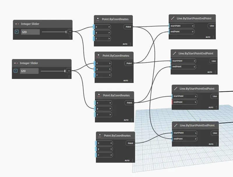
- The third line or we can say that the third wall have been created using the dynamo as shown in the below figure:
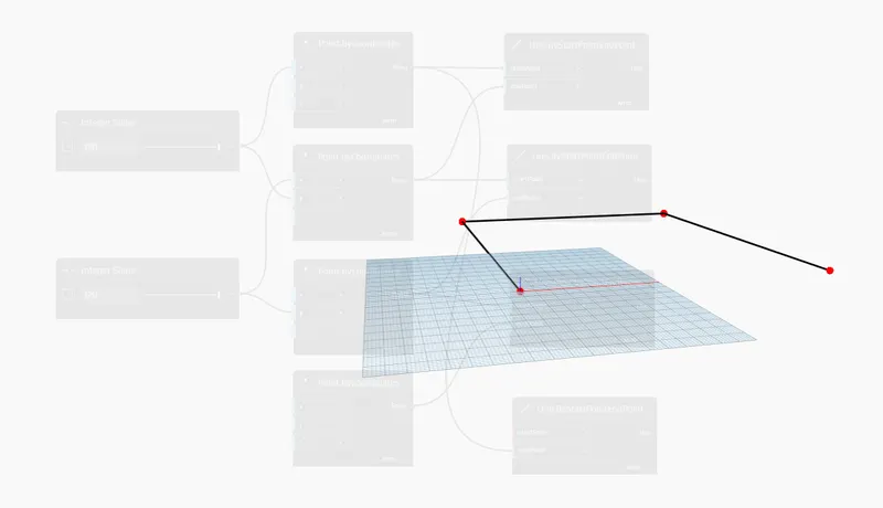
- now we have to create one more wall or line in order to complete this connection so for this we have to connect the Fourth box of PointsByCoordinates with the Endpoint of the third box of the Line.ByStartPointEndPoint. In this way our connection for creating the walls have been completed as shown in the below figure:
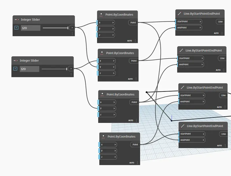
- Now our layout for creating the walls have been completed as shown in the below figure:
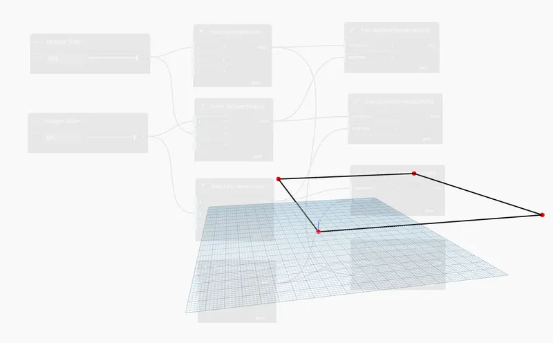
- This is how it will be looking like in the Revit software in the 2D and the 3D space as shown in the below figure:
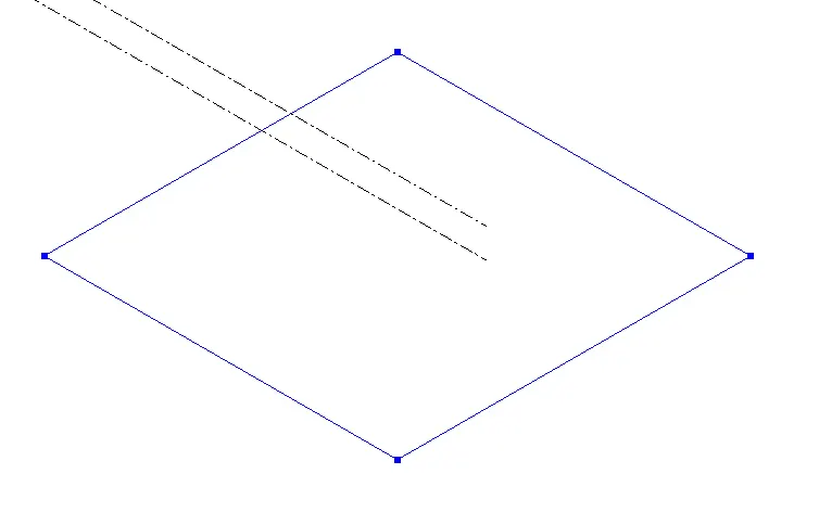
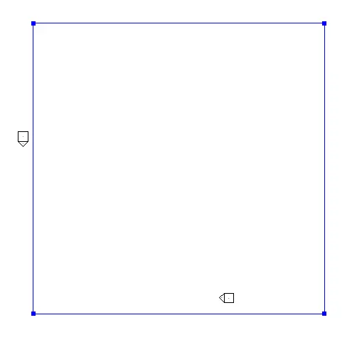
- After this we have to create the connections for the levels,width of the wall,height of the walls,flooring etc.
- So in order to do so first we have to again go to the search bar in that bar we have to search for the List and then there is an option called List Create as shown in the below figure:
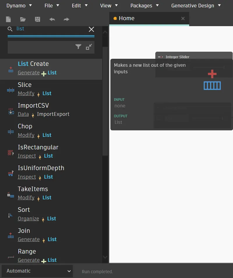
- A box of List Create have been appeared on the screen as shown in the below figure:
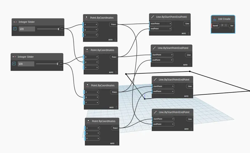
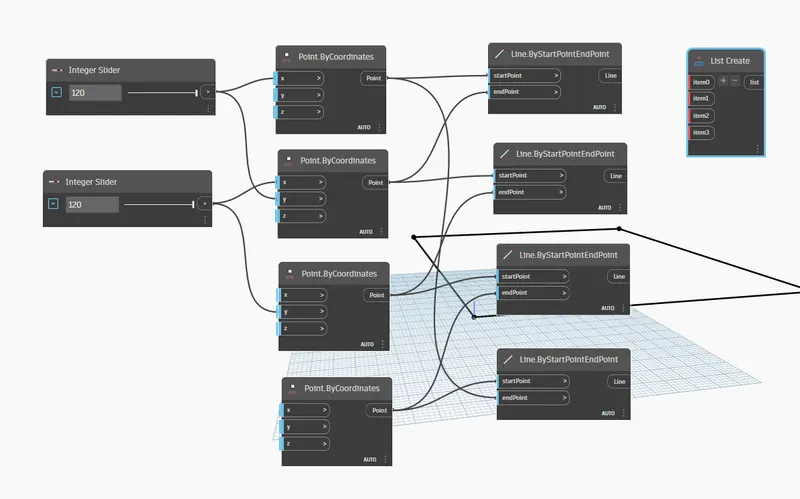
- This list create box contains element called Item 0. Now we have to increase the number of items in the list create box because we need items option for creating levels,walls,floor etc. So just increase the number upto three, Item 1,Item 2 and Item 3. As shown in the below figure:
- Now we will be creating the connections for the List Create.
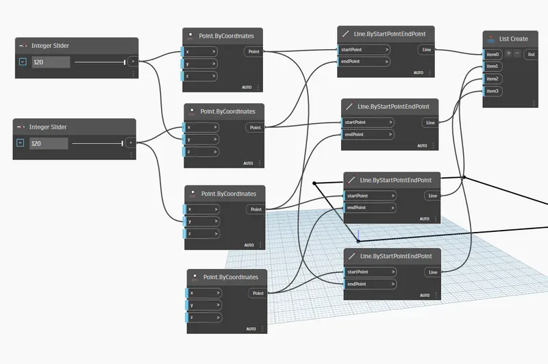
- Connect the first box of the Line.ByStartPointEndPoint with the Item 0 in the List create box.
- Similarly connect the second box of the Line.ByStartPointEndPoint with the Item 1 in the List create box.
- Connect the third box of the Line.ByStartPointEndPoint with the Item 2 in the List create box.
- Connect the fourth box of the Line.ByStartPointEndPoint with the Item 3 in the List create box.
- These connections have been shown in the below figure:
- After this we will be creating the levels,wall type,height etc. So lets see how we can create all these in the dynamo.
- So first of all we have to create the levels,in order to create the levels first we need to go to the search bar in that search for the levels as shown in the below figure:
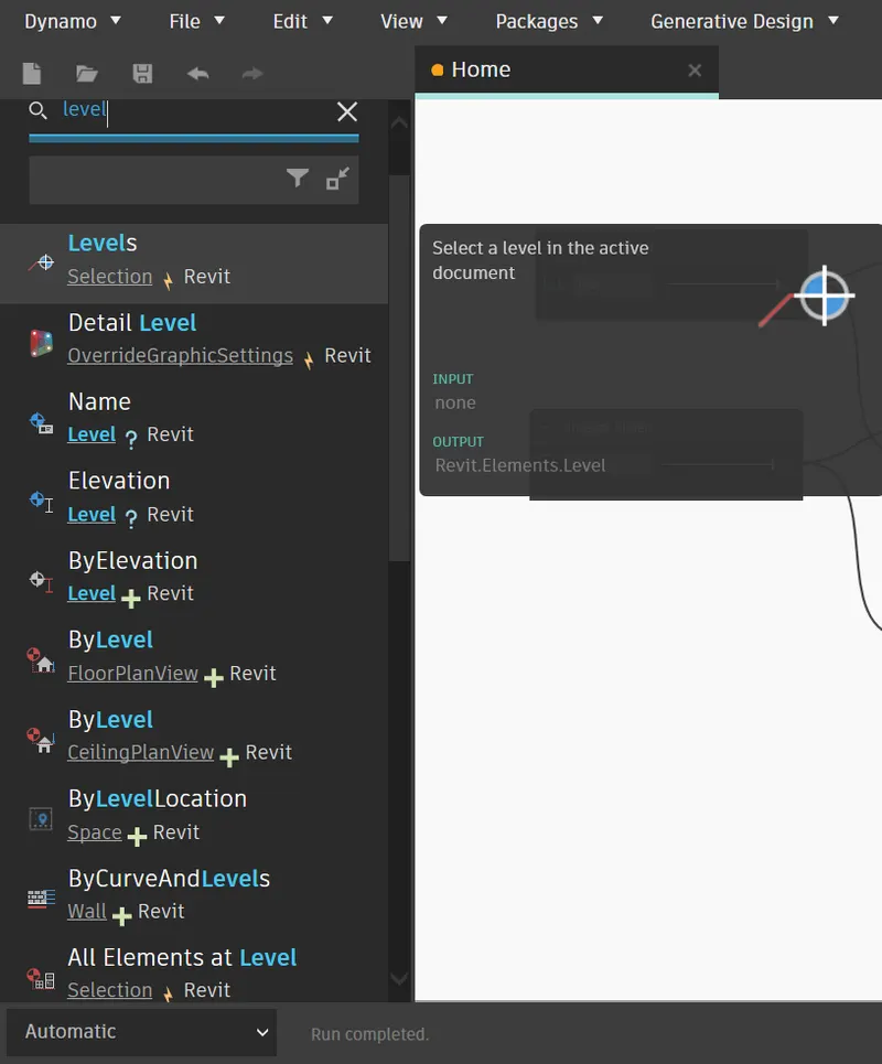
- After selecting the level option a box for levels appears on the screen as shown in the below figure:
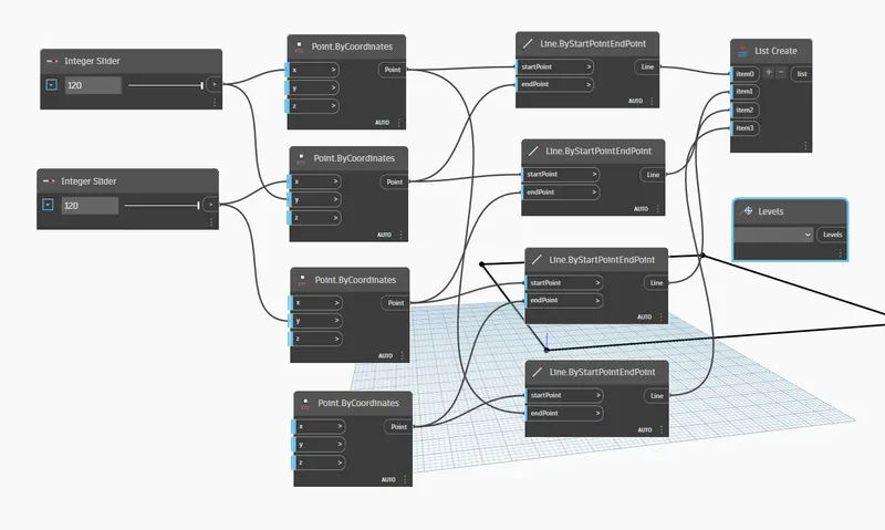
- Similarly go to the search bar and type wall then there will be an option called Wall type just click on that option as shown in the below figure:
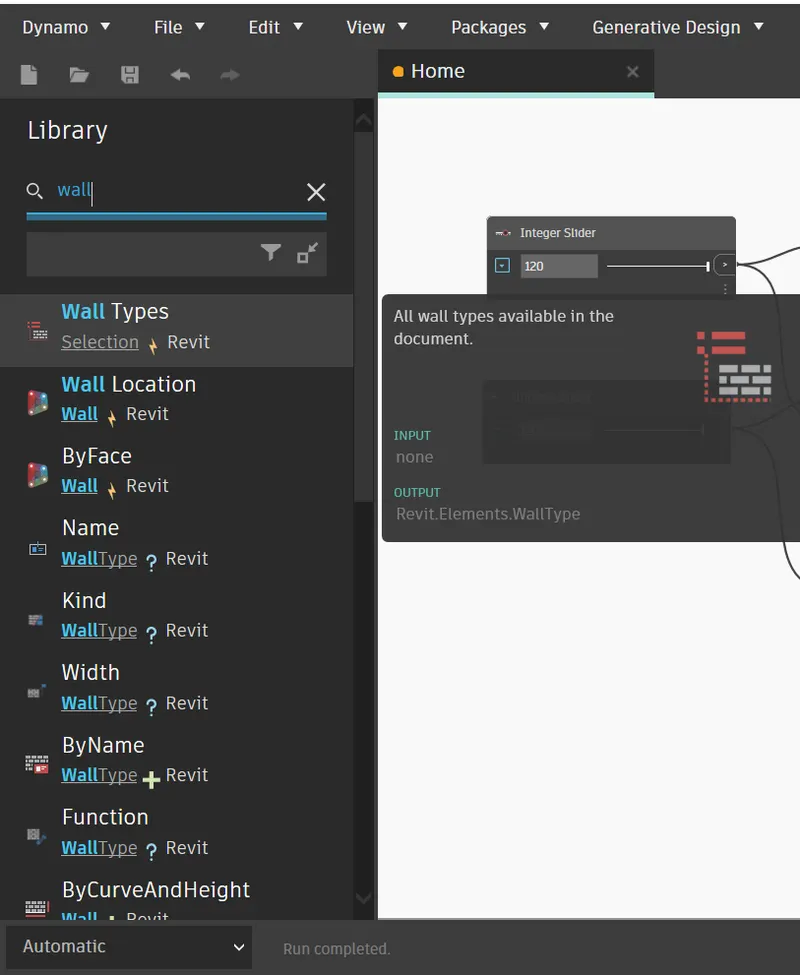
- After selecting the wall type option a box for wall type appears on the screen as shown in the below figure:
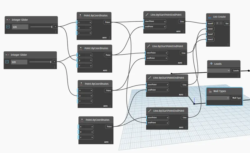
- Again go to the search bar and type integer then there will be an option called integer slider just click on that option as shown in the below figure:
- After selecting the Integer slider option a box for wall type appears on the screen as shown in the below figure:
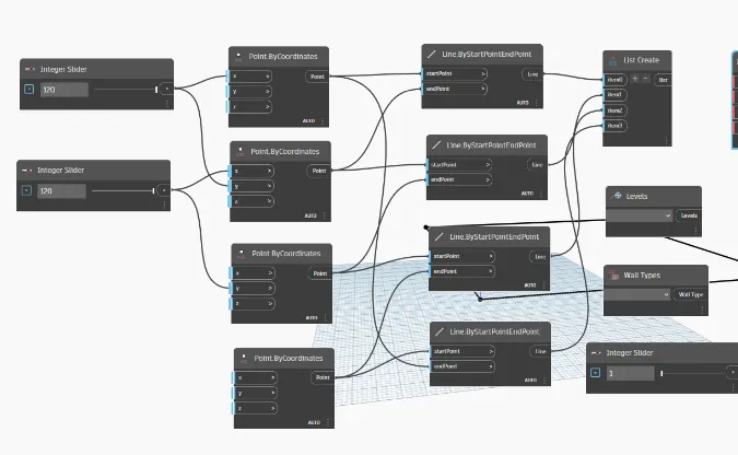
- Again go to the search option type wall in the search bar there is an option ByCurveAndHeight just click on that as shown in the below figure:
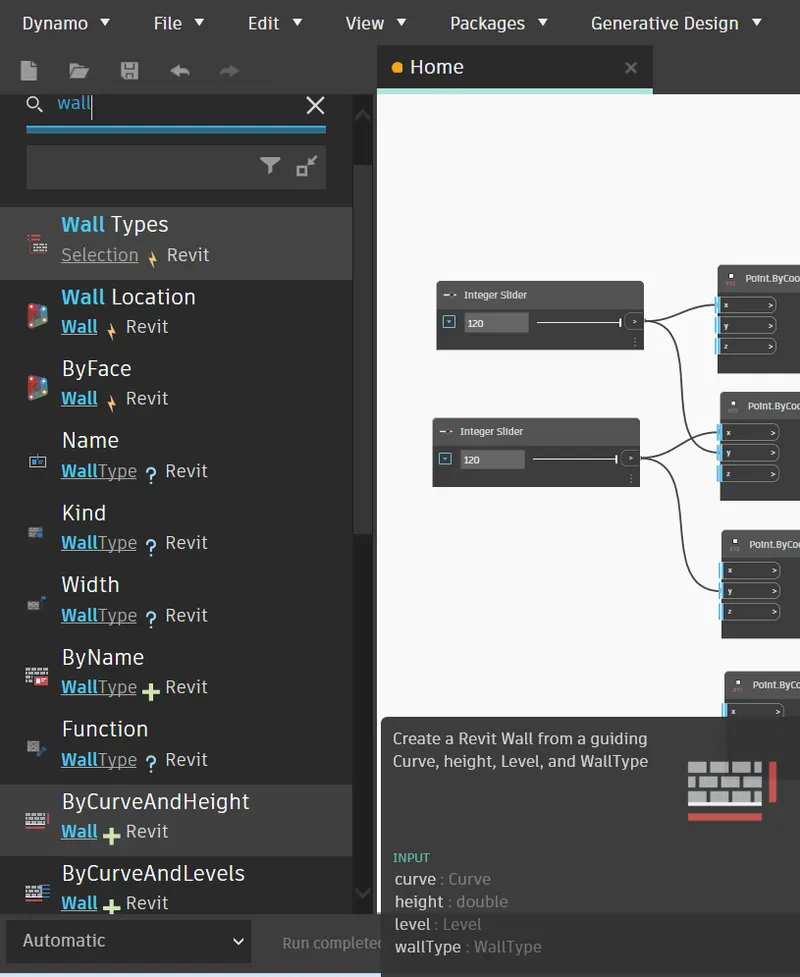
- After selecting the ByCurveAndHeight option a box for ByCurveAndHeight appears on the screen as shown in the below figure:
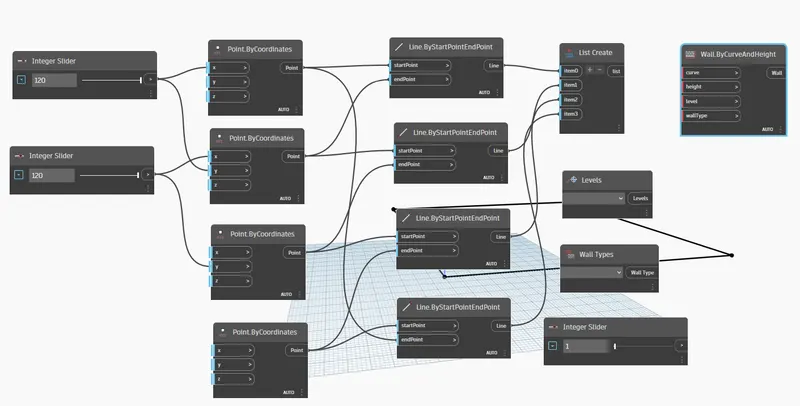
- After doing this,we will be doing the connections.
- So first of all we have to set the level, wall type and the integers after doing this we will be able to do the connections.
- So first we will be setting a level here i have set the level as Level 1 as shown in below figure:
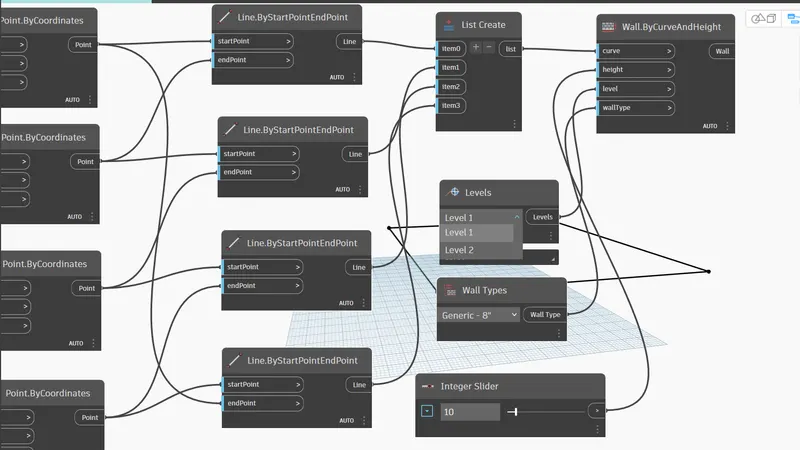
- Now we will be doing the wall type,here i am selected the wall type as Generic-8" as shown in the below figure:
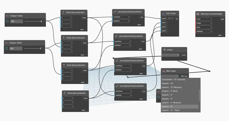
- And set the integer slider as 10, because i want the height of the wall is 10 as shown in the below figure:
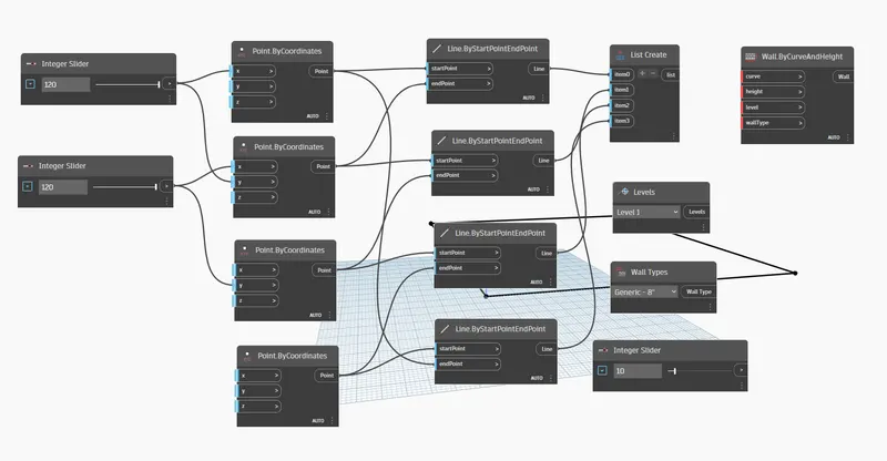
- So now we will be doing the connections,
- First of all connect the List create box with the Curve option in the WallByCurveAndHeight box.
- Next we will be connected Levels box with the Levels in the WallByCurveAndHeight box.
- Next connect wall type with the wall type in the WallByCurveAndHeight box.
- And connect the integer slider with the Height option in the WallByCurveAndHeight box, because integer slider is to be considered as the height of the wall, so connect the integer slider to the height option as shown in the below figure:
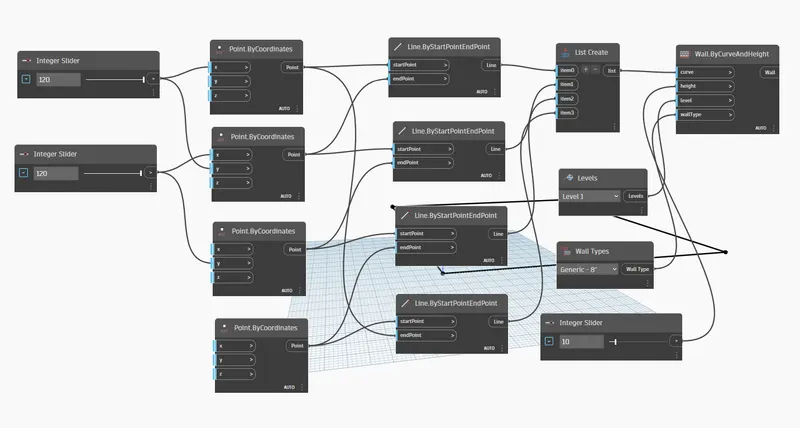
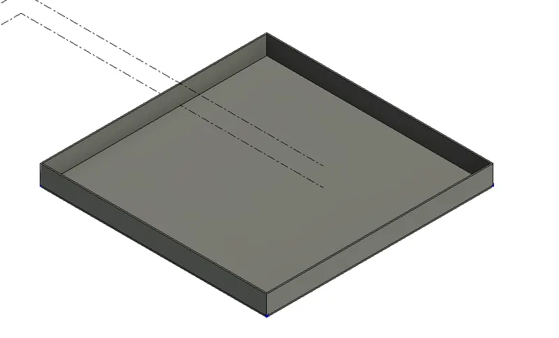
- The wall have been created using the Dynamo, the completed wall is shown in the Revit:
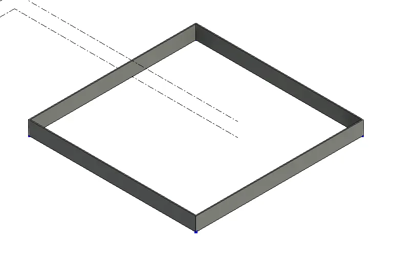
- This is how it will be look like in the Revit software.
- Now the final step is to create the floor.
- So in order to create the floor again we have to go to the search bar, in the search bar search for the Floor there will be option called Floor type click on that option as shown in the below figure:
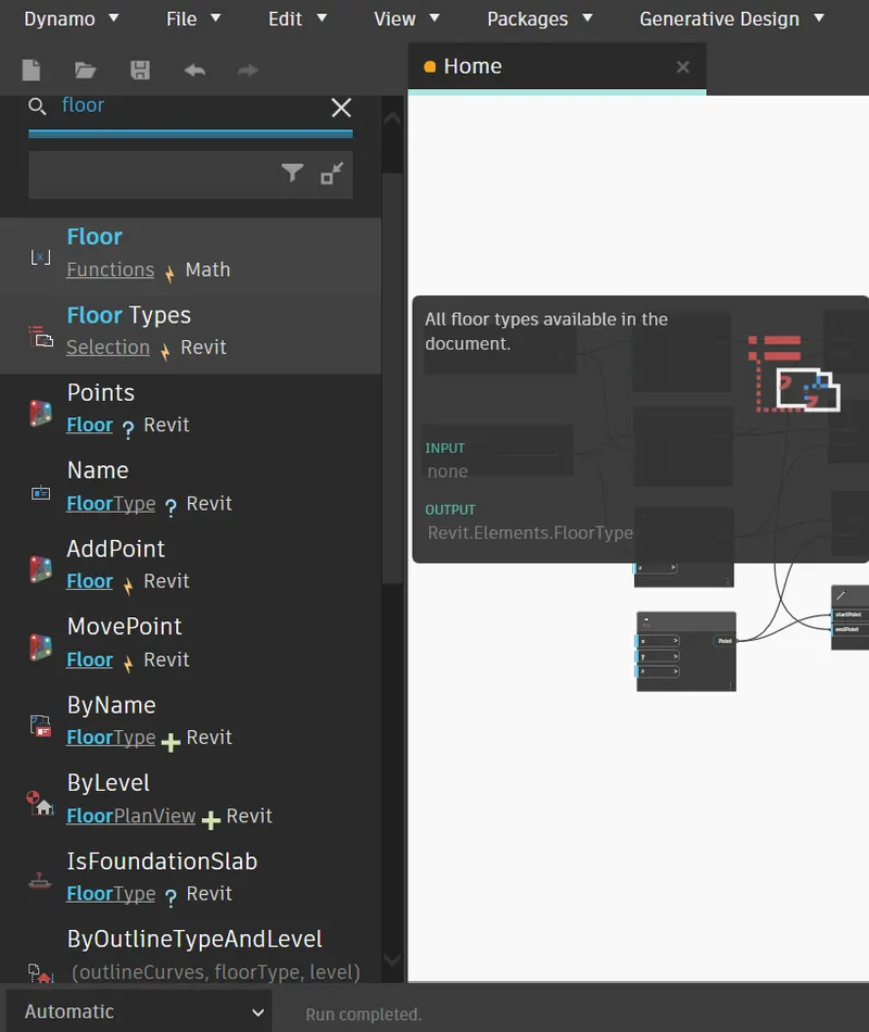
- After selecting the floor types option a box for floor type appears on the screen as shown in the below figure:
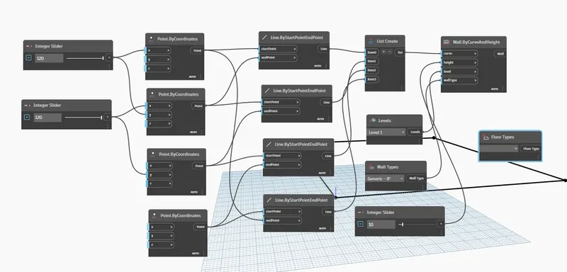
- Now again go to the search bar again search for the Floor then there will be an option called ByOutlineAndLevel as shown in the below figure:

- After selecting the ByOutlineAndLevel option a box for ByOutlineAndLevel appears on the screen as shown in the below figure:
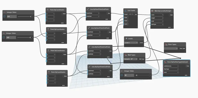
- The ByOutlineAndLevel option contain three elements called Floor type,level and outline curves.
- So in order to create the connections first we need to determine the floor type. Here i choose Generic-12" Filled as shown in the below figure:
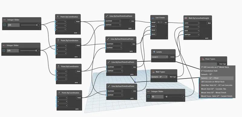
- Now connect the three elements of ByOutlineAndLevel.
- Connect the first element Outline Curve of ByOutlineAndLevel with the List Create box.
- The second element floor type with the floor type box.
- And the last element is Levels, so connect the level with the Levels box as shown in the below figure:
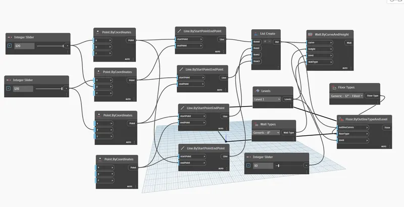
- Now or wall is completed with the floor using the Dynamo as shown in the below figure:
FINAL RESULT:
The connections using the Dynamo:
And the Final product:
Question 3) Create an array of model elements in Revit. Use dynamo to vary the properties of model elements by using the slider or code block.
AIM: Using dynamo create an array of model elements in Revit. Use dynamo to vary the properties of model elements by using the slider or code block.
INTRODUCTION: Dynamo is a visual programming software. Now a days we are in need of the dynamo because in the construction industry or we can say that the project oriented industries are fastly moving towards the artificial intelligence or we can say that they are moving towards the machine learning.Dynamo also enhance the project process and work flow.Now a days people are leaning towards the dynamo in order to improve their work process and enhances the project process. It is a visual programming tool that helps in expressions we can arrange graphics,texts,as a part of its syntex secondary notation.Inspite of creating the programme textually, this programming language it allows the user to manupulate the graphical elements in the interactive manner.In dynamo we eill be laerning about the certain keywords like wire,nodes,input,output etc, and we will be laerning these such as wire,node in order to achieve the purpose that we are looking for.So here we will be learning about how to create a set of sinusoidal points and using those points haw can we create the curve and after creating the curve we will be creating the surface using the same sinusoidal points and curve in a very detailed manner.All the detailed process has been discussed below:
PROCEDURE:
- First of all go to the revit software open that software.
- And then create the new template using the New option in the home page of the revit.
- Now create a imperial template,go to the browse option there search of the English-imperial option and then click on the option default and then option OK.
- Now our imperial template have been created as shown in the below figure:
- So to create an array of model element in Revit,first we need to go to the Architectural tab,from that tab we need to select any model element,here i have choosen the Architectural columns. So just go to the Architectural tab and there click on the architectural column as shown in the below figure:
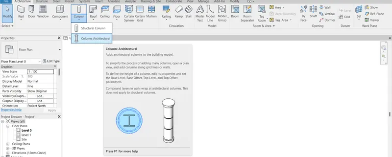
- And then i have created 4 numbers of column in the Revit software as shown in the below figure:

- Now go to the Manage toolbar there is an option called Dynamo,click on that option as shown in the below image:
- Now the Dynamo home page opens, in that home page there is an option called New just click on that option as shown in the below image:
- A new workspace or we can say that a new file opens as shown in the below image:
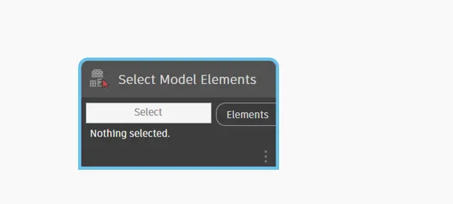
- From there there is a box at the left side in that box there is an option called search,so go to that search tab and just write Model element and there are multiple options regarding model elements just choose Select Model Elements as shown in the below image:
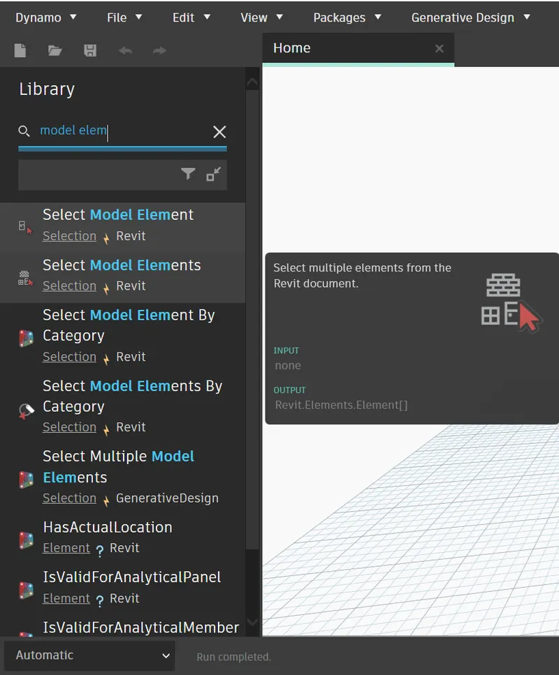
- After selecting the Select Model Elements option a box for Select Model Elements appears on the screen as shown in the below figure:
- Now again go to the search bar again search for the Rotation then there will be an option called Set Rotation as shown in the below figure:
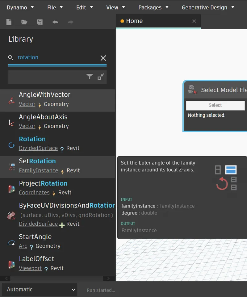
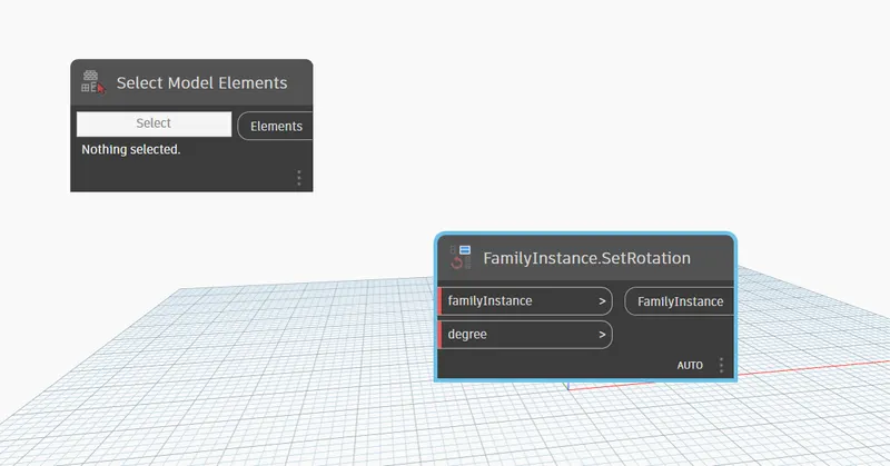
- After selecting the Set Rotation option a box for Set Rotation appears on the screen as shown in the below figure:
-
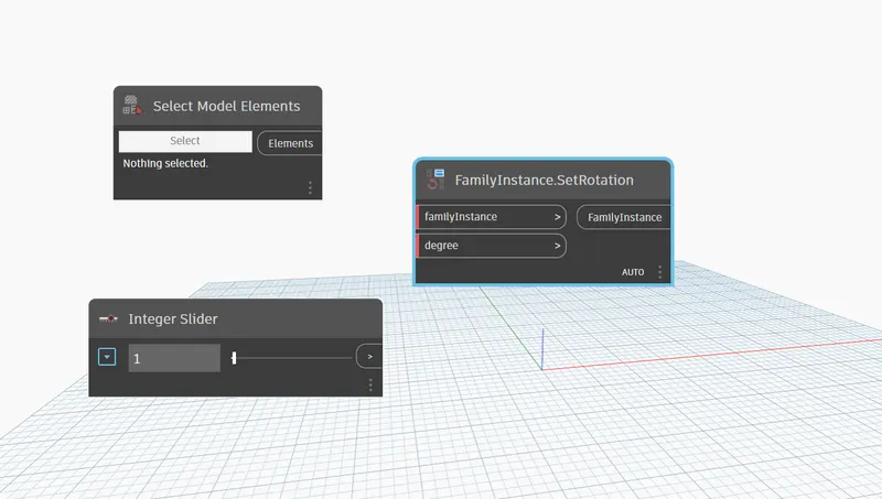
Now again go to the search bar again search for the integer then there will be an option called Integer slider as shown in the below figure:
- After selecting the Integer slider option a box for Integer slider appears on the screen as shown in the below figure:
- Now do the connections.
- First of all select the model elements by clicking on the search option in the Select Model Element.
- And then give the angle to the Integer slider as 45 degree.
- Now connect the Select Model Elements with the Family Instances of box FamilyInstances.SetRotation.
- Now connect the integer slider with the degree of the FamilyInstances.SetRotation.
- Now the connection is done.
- The connections have been shown in the below figure:
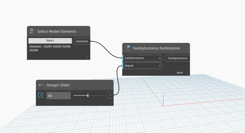
- Now we can be able to see the difference in the Revit software, just go to the revit software and check whether the columns had been rotated or not.
- The columns have been completely moved with the 45 degrees as shown in the below figure:

FINAL RESULT:
The connections using the Dynamo:
And the final result:
Question 4) Create a conceptual mass in Revit and develop a parametric column by dividing the surfaces and apply the concepts similar to used in parametric walkway modelling. Use triangular bent or square shaped panels to add finish to the parametric column.
AIM: Using dynamo create a conceptual mass in Revit and develop a parametric column by dividing the surfaces and apply the concepts similar to used in parametric walkway modelling. Use triangular bent or square shaped panels to add finish to the parametric column.
INTRODUCTION: Dynamo is a visual programming software. Now a days we are in need of the dynamo because in the construction industry or we can say that the project oriented industries are fastly moving towards the artificial intelligence or we can say that they are moving towards the machine learning.Dynamo also enhance the project process and work flow.Now a days people are leaning towards the dynamo in order to improve their work process and enhances the project process. It is a visual programming tool that helps in expressions we can arrange graphics,texts,as a part of its syntex secondary notation.Inspite of creating the programme textually, this programming language it allows the user to manupulate the graphical elements in the interactive manner.In dynamo we eill be laerning about the certain keywords like wire,nodes,input,output etc, and we will be laerning these such as wire,node in order to achieve the purpose that we are looking for.So here we will be learning about how to create a set of sinusoidal points and using those points haw can we create the curve and after creating the curve we will be creating the surface using the same sinusoidal points and curve in a very detailed manner.All the detailed process has been discussed below:
PROCEDURE:
- First of all go to the revit software open that software.
- And then create the new template using the New option in the home page of the revit.
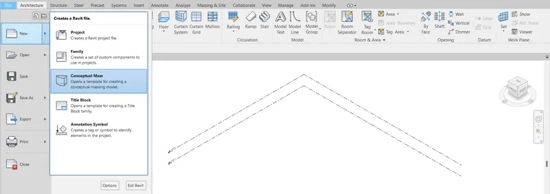
- Now go to the file tab there is an option New in that option click on the another option Conceptual mass click on that as shown in the below figure:
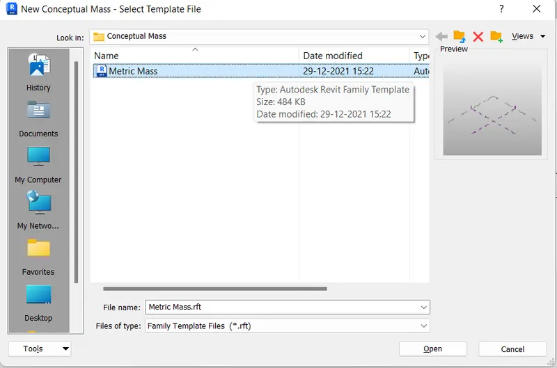
- After that a new dialouge box opens named as New Conceptual Mass- Select template file, in that box there is an option Metric Mass just click on that and press ok just as shown in the below figure:
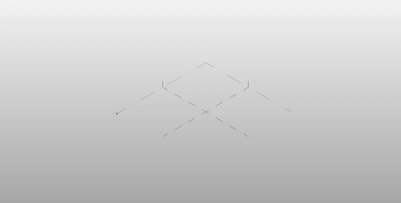
- Now the workplace will be looking like the below image:
- After this go to the Elevation level and create the levels at the distance of the 12' as shown in the below figure:
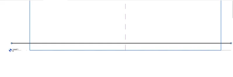
- After creating the level go to the floor plan. The floor plan will look like the below image after we have created the level of 12' height.
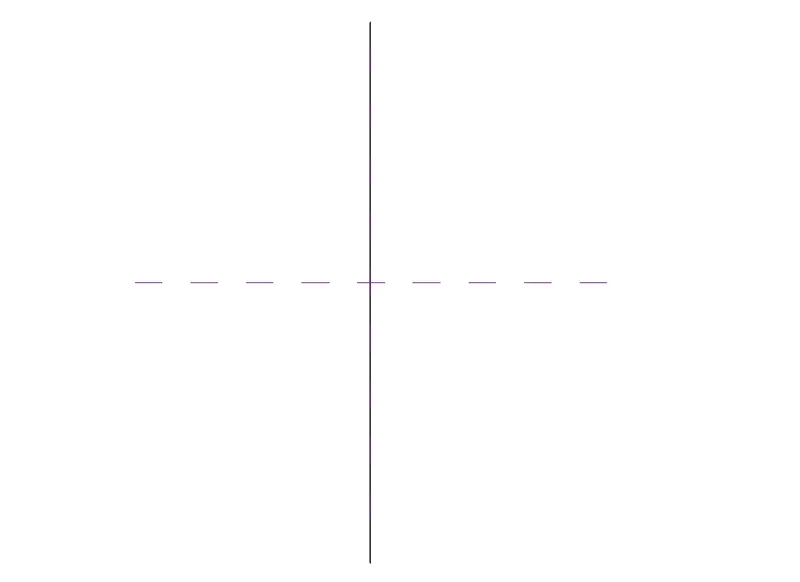
- Then go to the Create toolbar there is an option called Model line click on that option as shown in the below image:

- Now after clicking on the model line there are multiple of options to create the model line,so from that option choose Spline through Points as shown in the below figure:

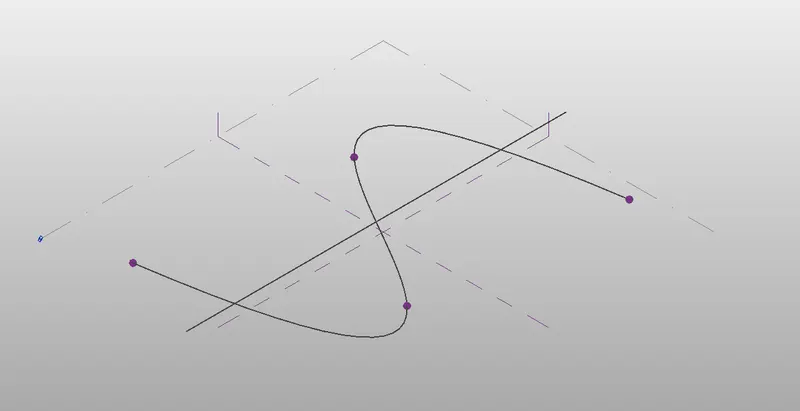
- After that we will be drawing a stucture using spline through points,the structure will be in S-shaped as shown in the below figure:
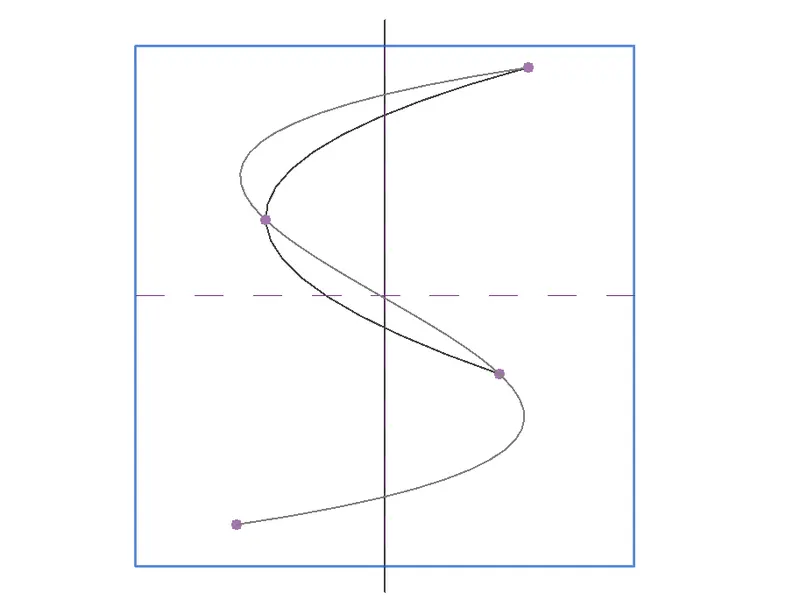
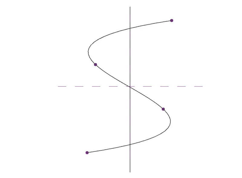
- Now go to the 3D view,then the structure in 3D will be looking like the below image:
- Now go to the Create toolbar there is an option called Set Plane just click on that option as shown in the below figure:

- Now using the option Set Workplane,set the plane as shown in the below figure:
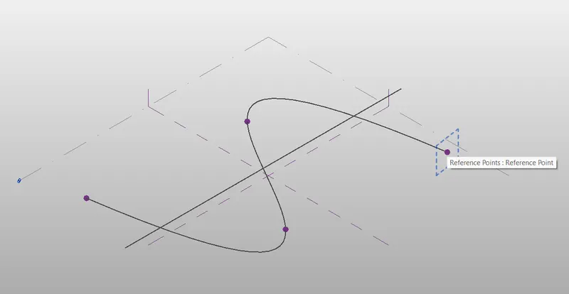
- Select the workplane for all the 4 points in the same manner.
- Now after selecting the plane there is an option called Show, by clicking that option we will be able to see the plane that we have just created as shown in the below image:

- Now after providing the workplane we will be providing the Circumscribed polygon. To provide the circumscribed polygon just go to the modify option there is an option in Model called Circumscribed Polygon as shown in the below figure:
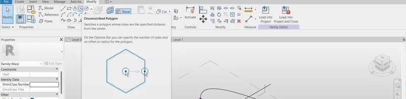
- Now provide the polygon on all the four points of the structure.
- Provide polygons of 12' because we have alredy created the level with the 12'.
- In order to view the workplane just click on the Show option and then create circumscribed polygon.
- While creating polygon we need to do it in a very proper and precise way otherwise it will go wrong so provide the polygon very carefully as shown in the below figure:
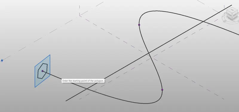
- Do the same procedure for all the points as shown in the below figure:
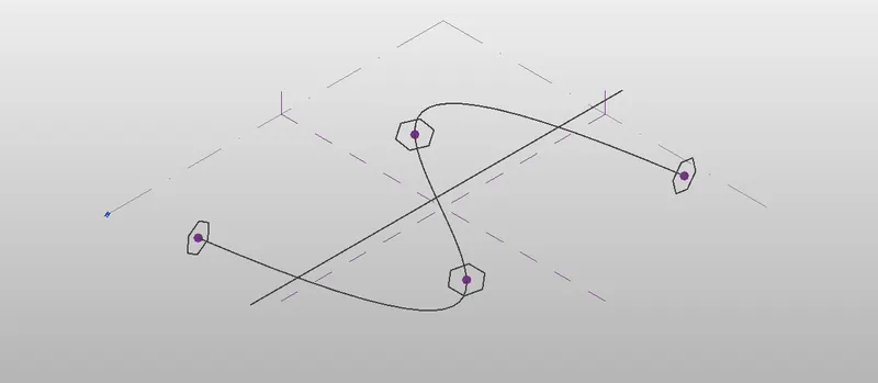
- After creating the circumscribed polygon we need to give this shape a solid form,so in order to do so we need to click on the spline line as shown in the below figure:
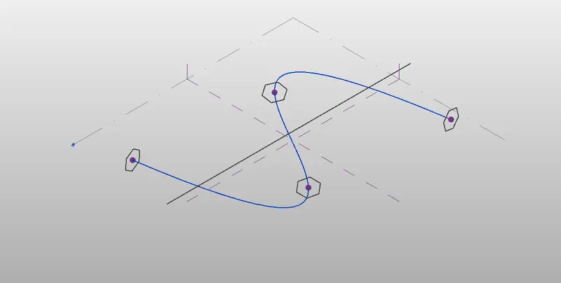
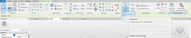
- Then go to the Modify|Lines tab there is an option called Create form in that tab there is an option Solid form click on that just as shown in the below figure:
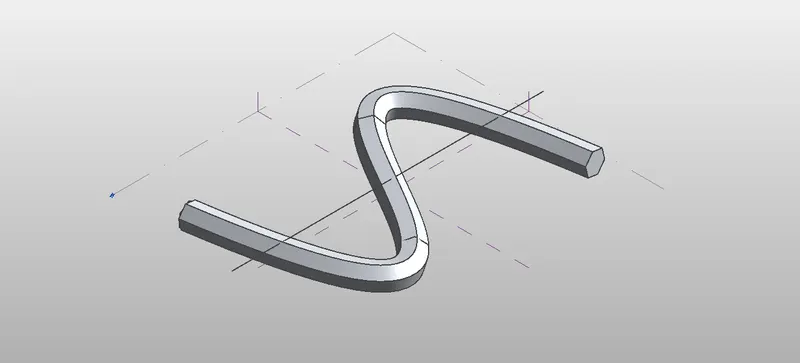
- After this the spline line will convert into a solid form as shown in the below image:
- Now select every thing as shown in the below figure:
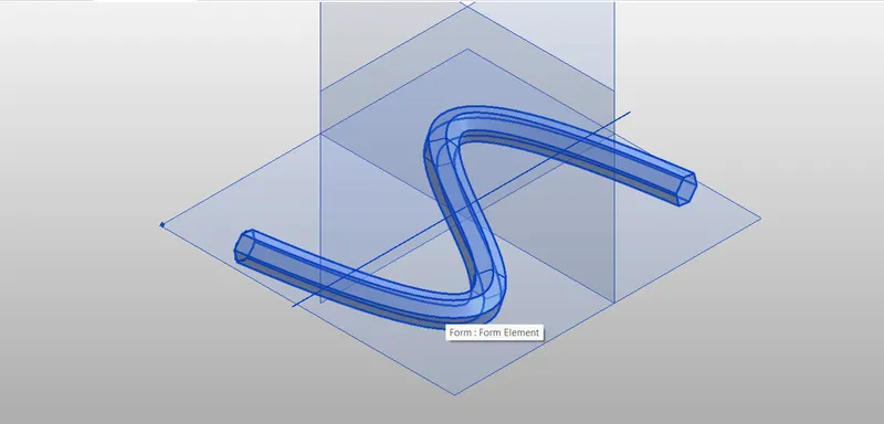
- Now there is an option at the Modify|Multiselect tab Divide surface just click on that option as shown in the below figure:
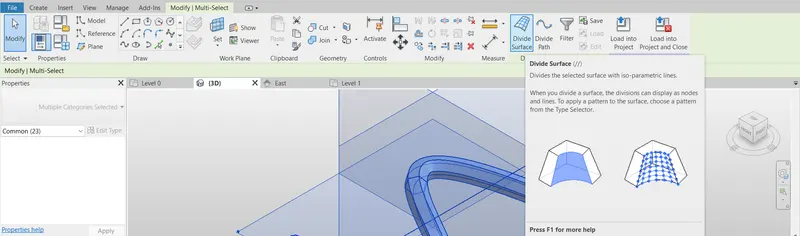
- After dividing the surface it will look like the below image.

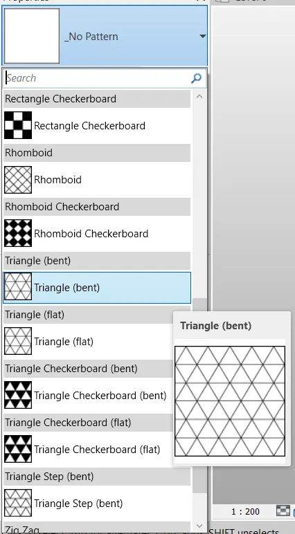
- Now go to the Properties box there is an option called No Pattern just click on that a number of patterns appears on the screen,from those option choose the pattern of your desire. Here i am choosing Triangle(bent) option as shown in the below image:
- So this is how the structure will look like after applying the triangle(bent) pattern.
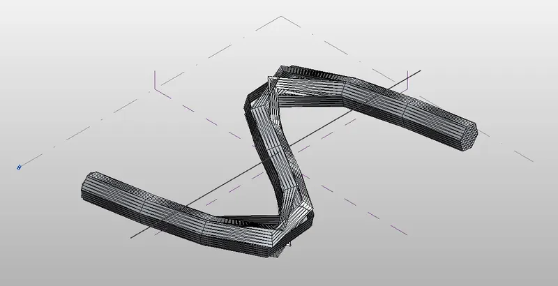
FINAL RESULT:
Question 5) Use Dynamo to work on developing a Parametric Stadium. List your parameters and use the visual programming approach to complete the modelling, You can use the concepts discussed in parametric high rise tower in class for reference.
AIM: Using dynamo work on developing a Parametric Stadium. List your parameters and use the visual programming approach to complete the modelling, You can use the concepts discussed in parametric high rise tower in class for reference.
INTRODUCTION: Dynamo is a visual programming software. Now a days we are in need of the dynamo because in the construction industry or we can say that the project oriented industries are fastly moving towards the artificial intelligence or we can say that they are moving towards the machine learning.Dynamo also enhance the project process and work flow.Now a days people are leaning towards the dynamo in order to improve their work process and enhances the project process. It is a visual programming tool that helps in expressions we can arrange graphics,texts,as a part of its syntex secondary notation.Inspite of creating the programme textually, this programming language it allows the user to manupulate the graphical elements in the interactive manner.In dynamo we eill be laerning about the certain keywords like wire,nodes,input,output etc, and we will be laerning these such as wire,node in order to achieve the purpose that we are looking for.So here we will be learning about how to create a set of sinusoidal points and using those points haw can we create the curve and after creating the curve we will be creating the surface using the same sinusoidal points and curve in a very detailed manner.All the detailed process has been discussed below:
PROCEDURE:
- First of all go to the revit software open that software.
- And then create the new template using the New option in the home page of the revit.
- Now create a imperial template,go to the browse option there search of the English-imperial option and then click on the option default and then option OK.
- Now our imperial template have been created as shown in the below figure:
- Now go to the Manage toolbar there is an option called Dynamo,click on that option as shown in the below image:
- Now the Dynamo home page opens, in that home page there is an option called New just click on that option as shown in the below image:
- A new workspace or we can say that a new file opens as shown in the below image:
- From there there is a box at the left side in that box there is an option called search,so go to that search tab and just write Integer and there are multiple options regarding integars as shown in the below image:
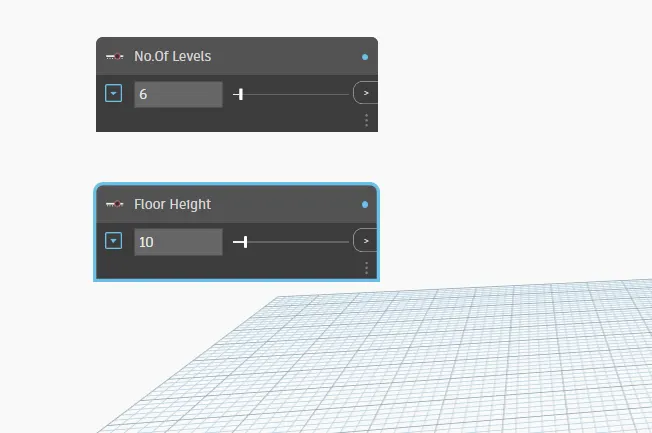
- So in that we have to go with the Integer Slider option just click on that option. A box with the name Integer slider appears on the workplace but we want two of integer slider so simply select the integer slider and copt that slider in order to copy that slider just press "Ctrl+C" and then paste it using the shortcut key "Ctrl+V" now the another integral slider appears on the screen. And change the name of the both integer slider one as the No.Of Levels and other one as Floor Height just as shown in the below figure:
- After this we will be going to the search bar once again,from there search Code block and there is an option called code block just click on that as shown in the below figure:
- After doing this a new box of Code block appears on the screen. Now give some code in the code block to create the elements like floor height and no. of levels,so just type 0..#levels..floorheight;
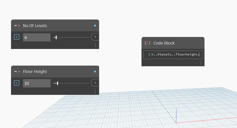
- Now the two different elements have been created in the Code block one is No.of Levels and the another one is Floor height as shown in the below figure:
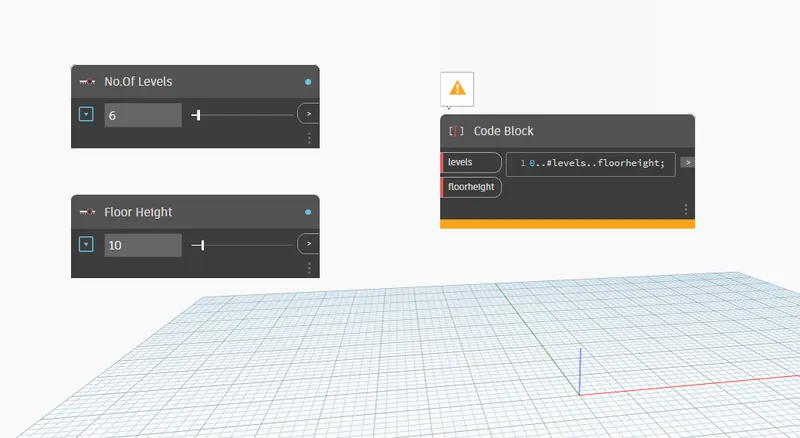
- Now make the connections for this.
- First connect the No.of Levels to the Levels of code block and then Floor height to the floor height of the code block as shown in the below figure:
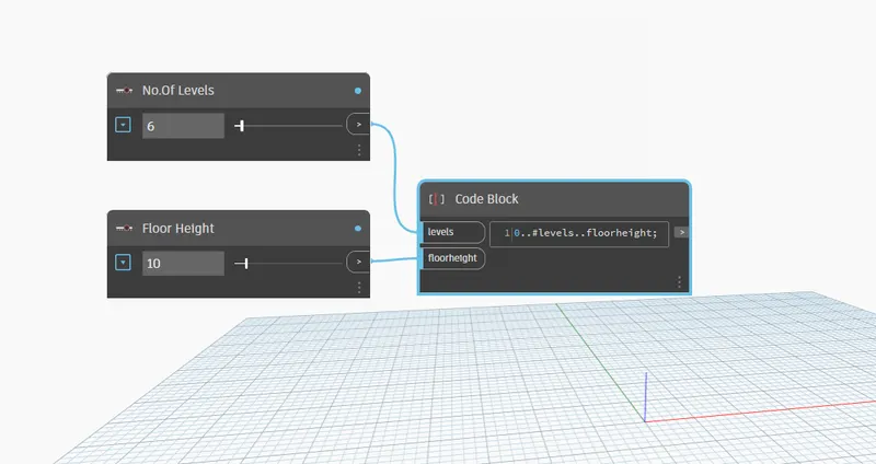
- Again go to that search tab and just write Integer and there are multiple options regarding integars just click on the Integar Slider as shown in the below image:
- So in that we have to go with the Integer Slider option just click on that option. A box with the name Integer slider appears on the workplace but we want 4 of integer slider so simply select the integer slider and copt that slider in order to copy that slider just press "Ctrl+C" and then paste it using the shortcut key "Ctrl+V" now the another 4 integral slider appears on the screen. And change the name of the both integer slider one as the Width,Length, Bottom Floor Rotation and the Top Floor Rotation just as shown in the below figure:
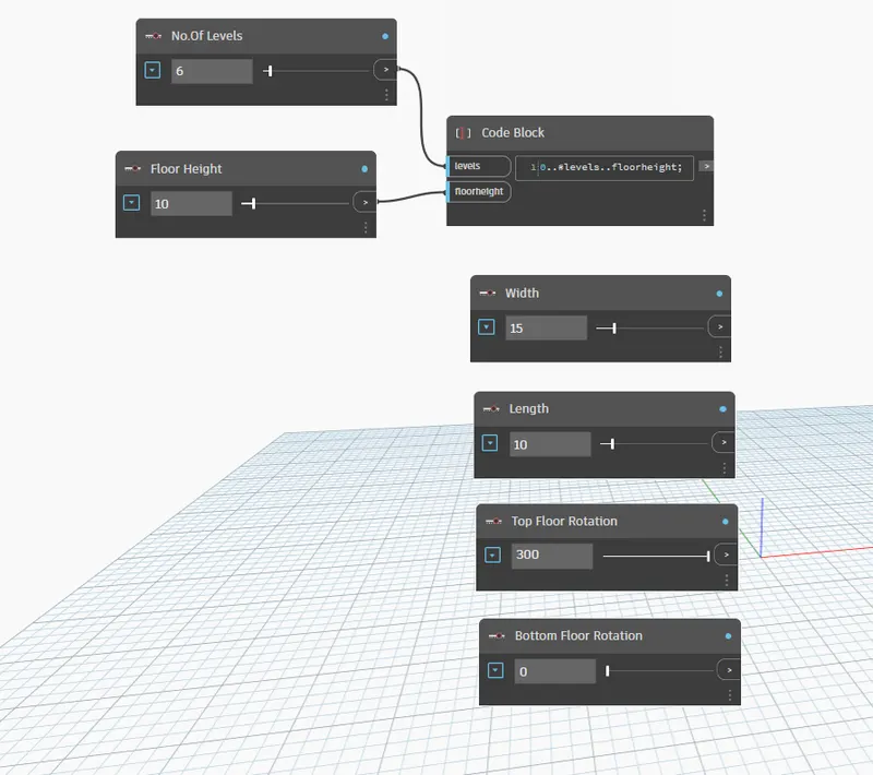
- Again go to that search tab and just write Co-ordinate system and there are multiple options regarding Co-ordinate system just click on the ByCartesianCoordinates as shown in the below image:
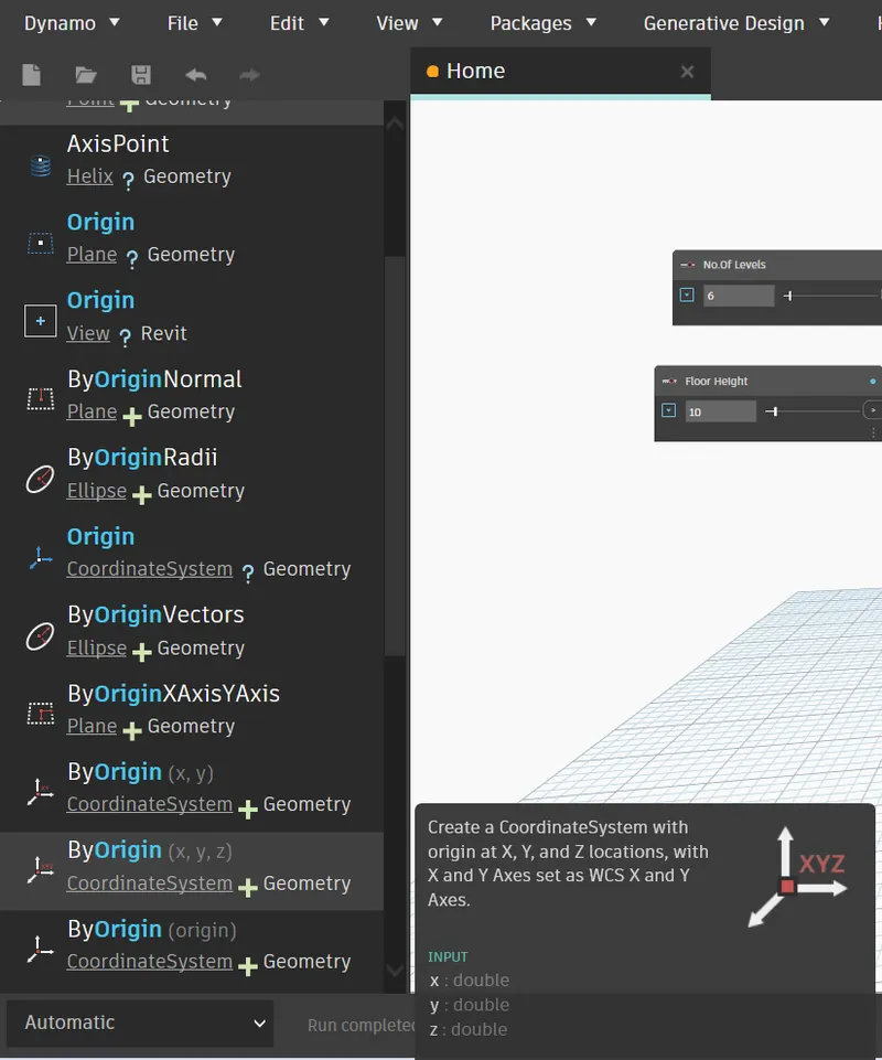
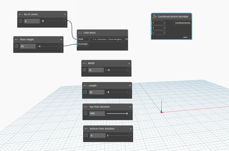
- After doing this a new box of Code block appears on the screen as shown in the below image:
- Again go to that search tab and just write rectangle and there are multiple options regarding rectangle just click on the ByWidthLength as shown in the below image:
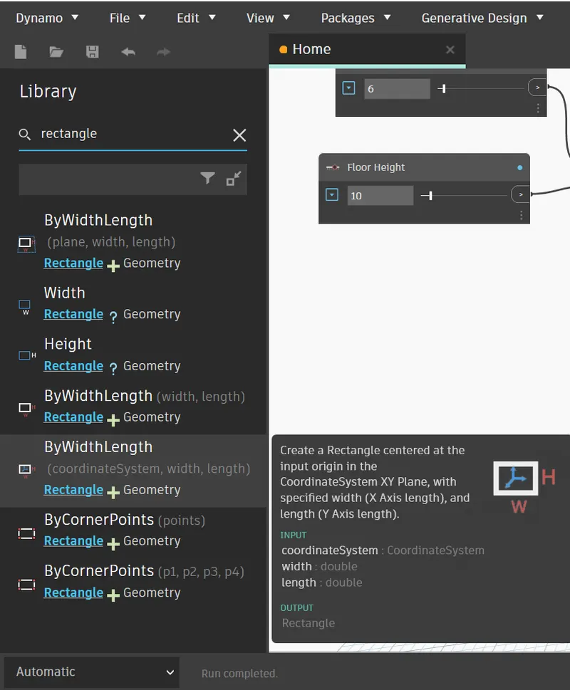
- After doing this a new box of Code block appears on the screen as shown in the below image:
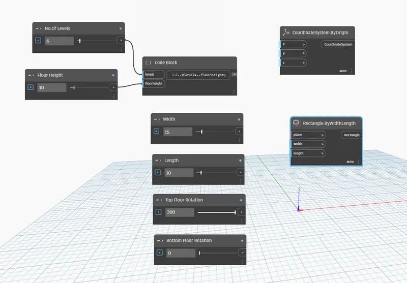
- Now connect the Code block with the z value of the CoordinationSystem.ByOrigin as shown in the below image:
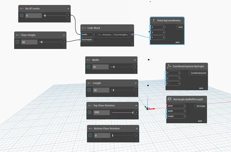
- We can see in the above image that the points have been created in the above image in the z-direction.
- Now connect the code block with the z value of CoordinateSystem.ByOrigin
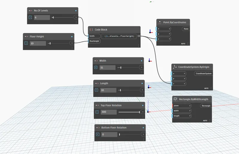
- Now make the connections as shown in the below figure:
- Connect the width of the Rectangle.ByWidthLength with the Width block.
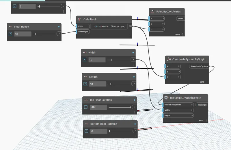
- Now the floors have been created at the height of 10 as shown in the below figure:
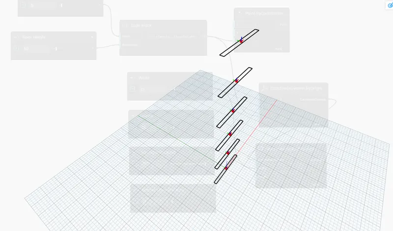
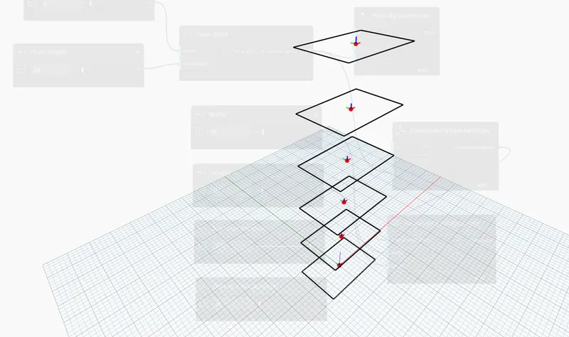
- After creating the levels do more connections.
- Connect the Length of the Rectangle.ByWidthLength with the Length block.
- Connect the top floor rotation block with the top of the code block.
- Connect levels with the level of the Rectangle.ByWidthLength block.
- And Connect the bottom floor rotation block with the bottom of the code block,as shown in the below figure:
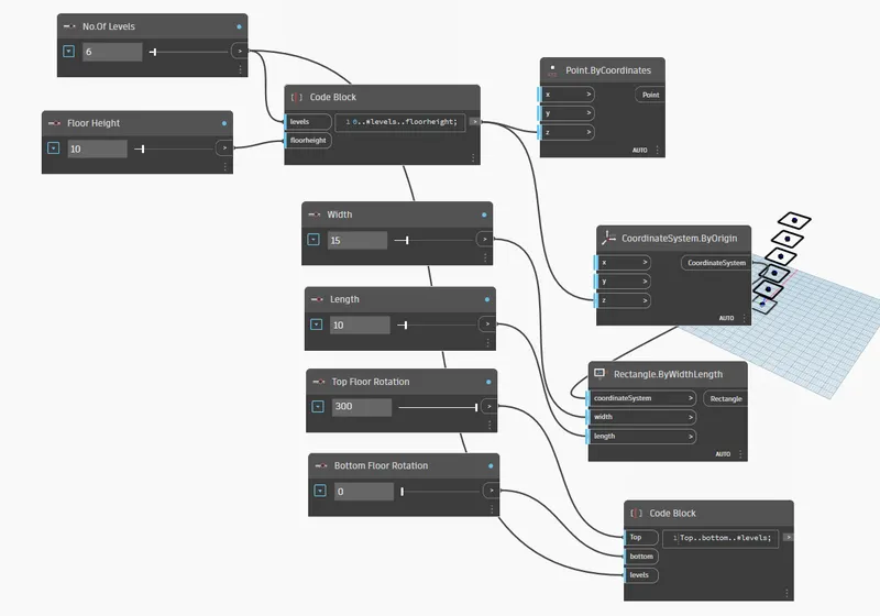
- Again go to that search tab and just write origin and there are multiple options regarding origin just click on the origion as shown in the below image:
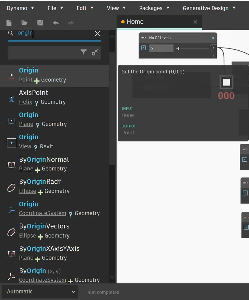
- Now do the all connections properly as shown in the below figure:
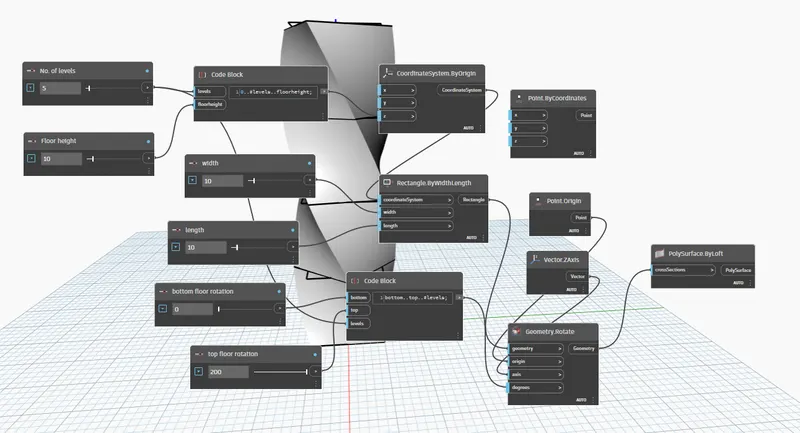
- Now the Parametric stadium has been created using the dynamo as shown in the below figure:
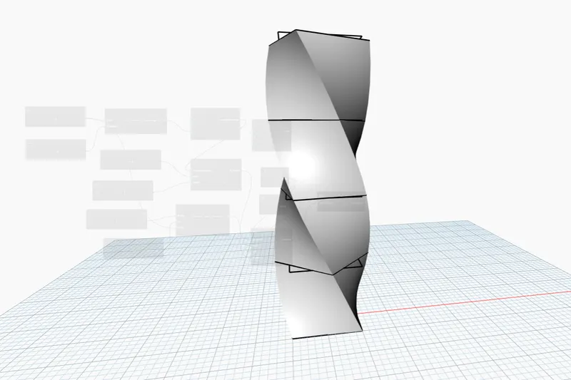
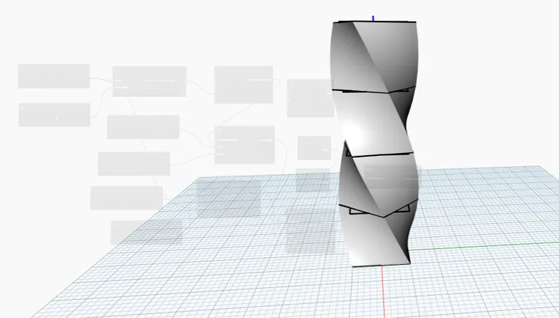
FINAL RESULT:
The connections using the Dynamo:
And the final product: