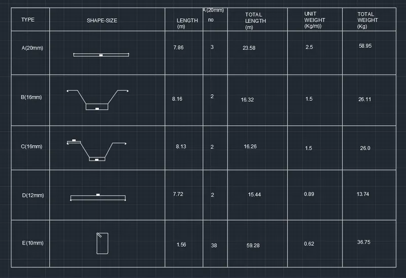
Creating Bar Bending schedule, Different Door types, and Creation of standard drawing templates using AutoCad
AIM :- To create Bar Bending schedule, Different Door types, and Creation of standard drawing templates using AutoCad.
Introduction :-
- Block :- A block is a combination of AutoCAD object types that make up a real-world object. For example, it could be a chair, manhole, door, utility pole, you name it.
- The general commands used for the drawings are as follows :-
- Line
- Rectangle
- Circle
- Erase
- Copy
- Trim
- Arc
- Breakpoint
- Mirror
- Offset
- Extend
- Array
- Move
- Rotate
- Dimension
- Text
- Fillet
PROBLEM 1 :-
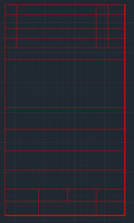
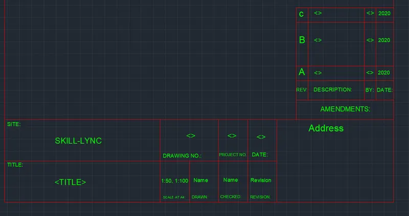
Aim :- To create the templates as shown in Figures and convert it into blocks with names as Custom1_titleblock and Custom2_titleblock respectively.
Introduction :-
- The tittle block is a template created in a sheet which contains the information or data regarding the drawing and also the information of the company and persons of the company responsible for the drawing.
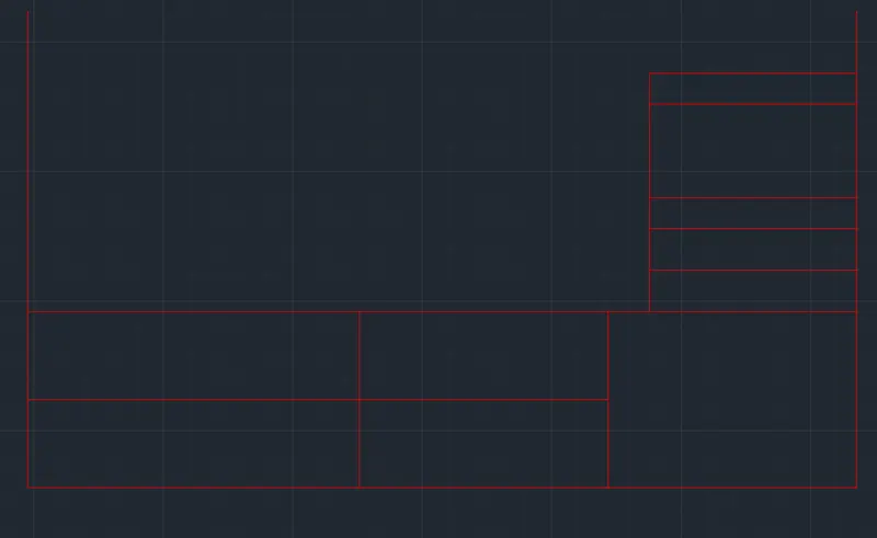
- The given title blocks custom1 and custom2, one with vertical title block at the right and another the bottom of the page.
- The tittle block contains information regarding the revision number of the drawings, title of the drawings, names of the persons involved in making of the drawing.
Procedure :-
- Open AutoCAD
- Type 'un' in command box and press enter
- Change units' type to decimal and precision to 0.00 and insertion scale to millimeters Change 'limits' to (O,O) and (5000,5000)
Step 1 :- Creating Layers
- Type "LA" in the command box and press enter.
- Open layer properties and create new layers by clicking on new layer icon.
Step 2 :- Creating Custom1_tittleblock
Change current layer to Table.
Type "rec" in the command box and press enter.
Draw a rectangle of dimensions 440mm length and 250mm.
Type "explode" in the command box and press enter.
Select the rectangle drawn and explode the rectangle.
Type "O" for offset command and press enter.
Specify offset distance as 20.
Select the upper egde of the rectangle and click at bottom.
Type "O" for offset command and press enter.
Specify offset distance as 30.
Select the last offseted line and click at bottom.
Type "O" for offset command and press enter.
Specify offset distance as 20.
Select the last offseted line and click at bottom.
Type "O" for offset command and press enter.
Specify offset distance as 20.
Select the last offseted line and click at bottom.
Type "O" for offset command and press enter.
Specify offset distance as 25.
Select the last offseted line and click at bottom.
Type "O" for offset command and press enter.
Specify offset distance as 100.
Select the last offseted line and click at bottom.
Type "O" for offset command and press enter.
Specify offset distance as 45.
Select the last offseted line and click at bottom.
Type "O" for offset command and press enter.
Specify offset distance as 45.
Select the last offseted line and click at bottom.
Type "O" for offset command and press enter.
Specify offset distance as 40.
Select the last offseted line and click at bottom.
Type "O" for offset command and press enter.
Specify offset distance as 40.
Select the last offseted line and click at bottom.
Type "O" for offset command and press enter.
Specify offset distance as 20.
Select the last offseted line and click at bottom.
Use the offset command and draw the vertical columns as the same as rows.
Type "tr" in the command box and press enter.
Trim the extra object in the table.
:- Creating Custom2_tittleblock
- Change current layer to Table.
- Type "rec" in the command box and press enter.
- Draw a rectangle of dimensions 400mm length and 200mm.
- Type "explode" in the command box and press enter.
- Select the rectangle drawn and explode the rectangle.
- Type "O" for offset command and press enter.
- Specify offset distance as 15.
- Select the upper egde of the rectangle and click at bottom.
- Type "O" for offset command and press enter.
- Specify offset distance as 45.
- Select the last offseted line and click at bottom.
- Type "O" for offset command and press enter.
- Specify offset distance as 15.
- Select the last offseted line and click at bottom.
- Type "O" for offset command and press enter.
- Specify offset distance as 20.
- Select the last offseted line and click at bottom.
- Type "O" for offset command and press enter.
- Specify offset distance as 20.
- Select the last offseted line and click at bottom.
- Type "O" for offset command and press enter.
- Specify offset distance as 100.
- Select the right edge of rectangle line and click on left.
- Type "O" for offset command and press enter.
- Specify offset distance as 20.
- Select the last offseted line and click at left.
- Type "O" for offset command and press enter.
- Specify offset distance as 30.
- Select the last offseted line and click at left.
- Type "O" for offset command and press enter.
- Specify offset distance as 30.
- Select the last offseted line and click at left.
- Type "O" for offset command and press enter.
- Specify offset distance as 30.
- Select the last offseted line and click at left.
- Type "O" for offset command and press enter.
- Specify offset distance as 30.
- Select the last offseted line and click at left.
- Type "tr" in the command box and press enter.
- Trim the extra lines in the table and make the table as per the question.
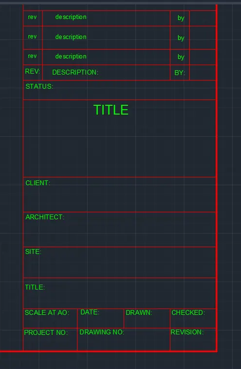
Adding texts to Custom2_tittleblock
- Change layer to "Text".
- Go to the "Annotate" bar and click on multi text.
- Set the height of the text and text style.
- Select the area and type the text as given ithe the question.
- Now select the typed text adn copy that text to the other places where the text required.
- Type "ed" for edit text and select the text to edit their it and change the different text as per the question.
RESULT
Aim :- To create the doors type for warehouse as shown in the question and create the blocks of each door using AutoCAD.
Procedure :-
Open AutoCAD
Type 'un' in command box and press enter
Change units' type to decimal and precision to 0.00 and insertion scale to millimeters Change 'limits' to (O,O) and (5000,5000)
:- Creating Layers
Type "LA" in the command box and press enter.
Open layer properties and create new layers by clicking on new layer icon.
Set the units to millimeters
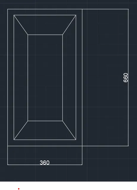
Created the door using line command of dimension length 660 & width 360
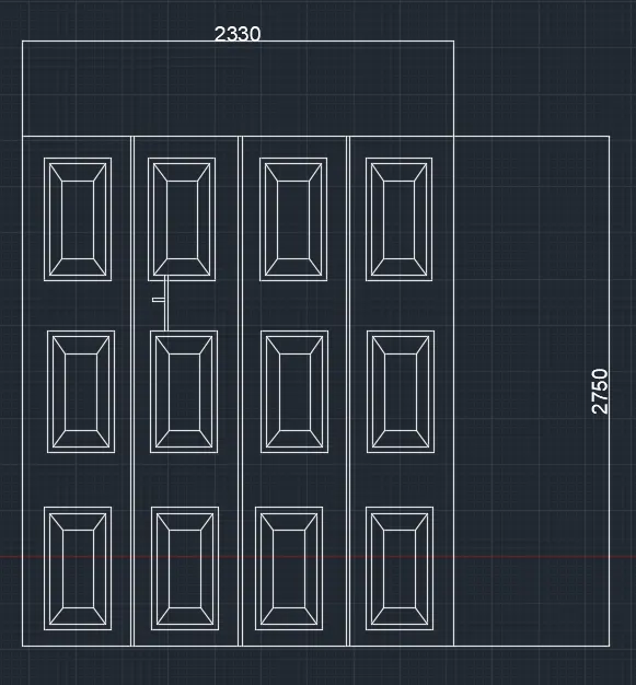
Now created the rectangle of given dimension length 2750 & widtgh 2300
Now copy & pasted the doors in required places
RESULT:
3)AIM:
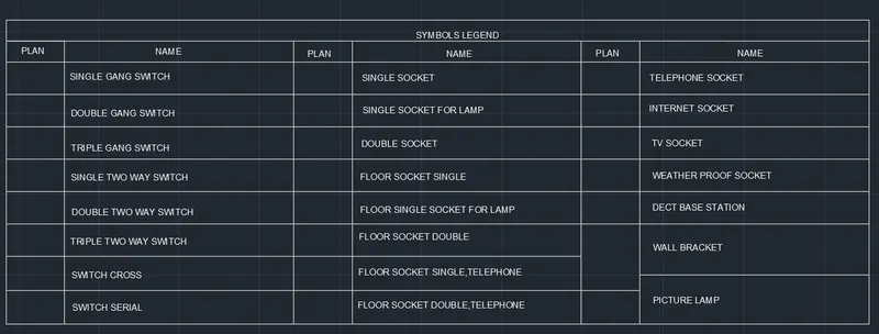
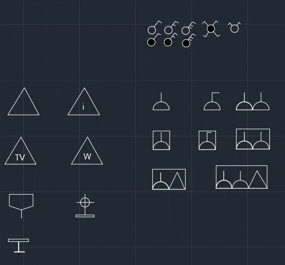
Create each symbol as a block with the name given in the legend. After creating the blocks arrange them in the legend as shown in the Figure.
PROCEDURE:
Create a table of 6 column & 10 rows
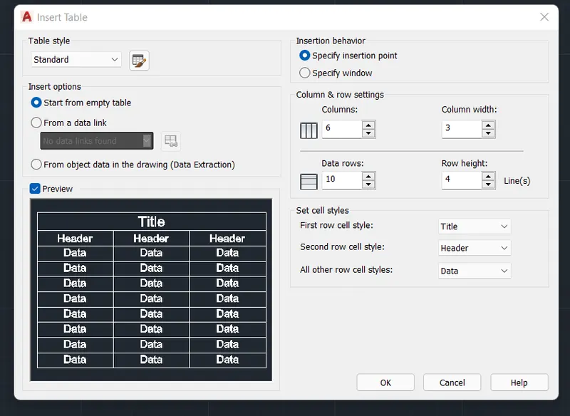
Type the words in created box using MTEXT
Symbols are created using circle,arc,rectangle,line command
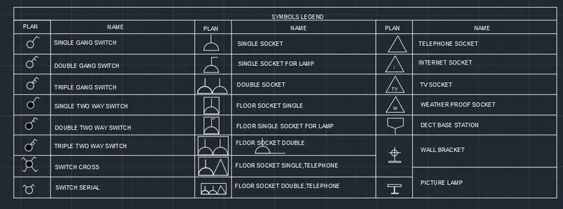
RESULT
4)AIM:
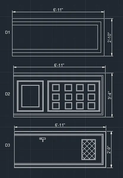
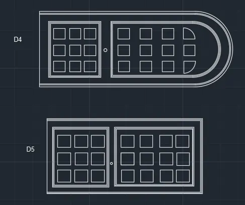
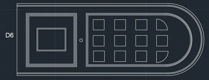
Create the door type for residential building as a block. Save the name of the blocks as type. Use given dimensions or assume dimensions as per industry standards.
PROCEDURE:
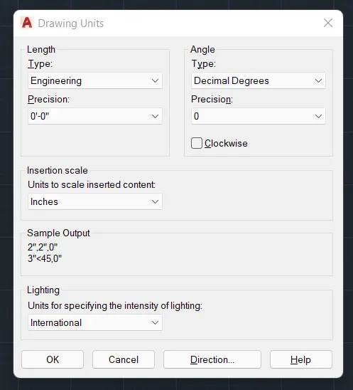
Set the units type emngineering , precision 0'-0",insertion scale to inches
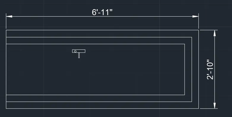
Draw door 1 of dimension length 6'-11" & width 2'-10"
create door 1 of dimension length 6'-11" & width 3'-4
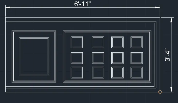
"
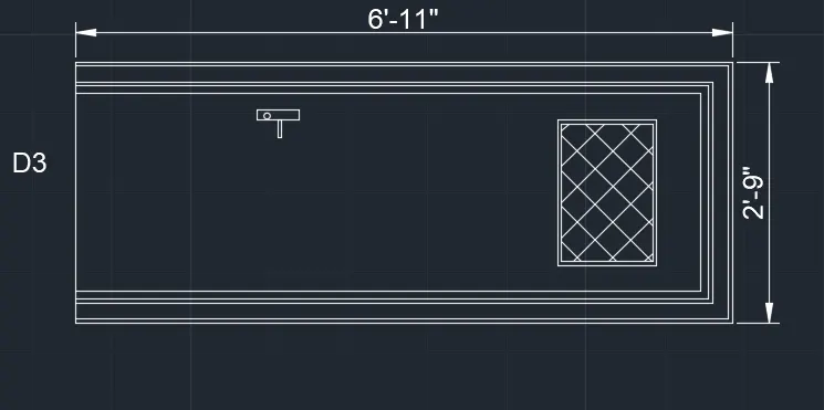
Create a door 3 of dimension length 6'-11" & width 2'-9"
create door 4 of dimension length 6'-11" & width 3'-4"
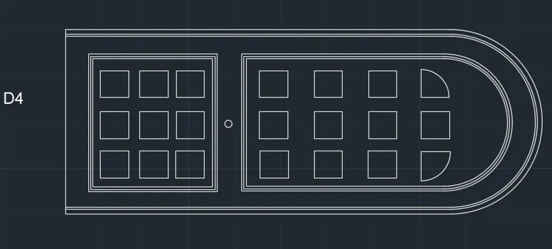
create door 4 of dimension length 6'-11" & width 3'-4"
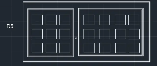
create door 4 of dimension length 6'-11" & width 3'-4"
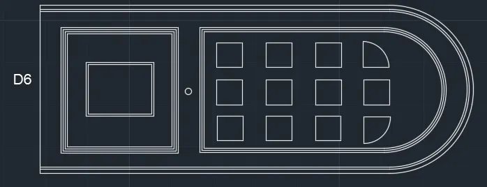
RESULT
5)AIM:
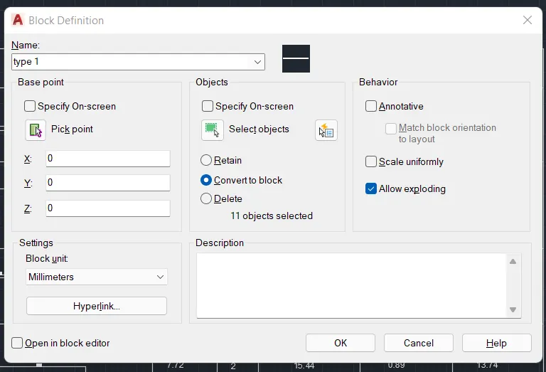
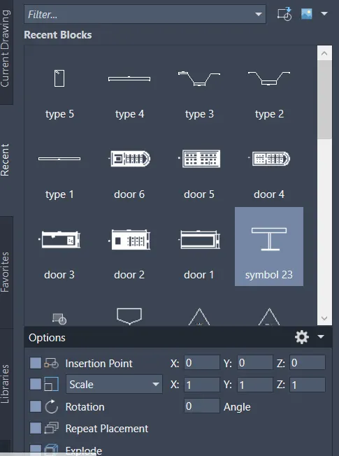
Create each shape as a block as shown in the Figure. Save the block and insert them on the table as shown in the Figure.
PROCEDURE:
Create each symbol as per given dimension
Create a block for each symbol & insert it
Create a table ,use MTEXT command for creating titles
RESULT