Creating Bar Bending schedule, Different Door types, and Creation of standard drawing templates using AutoCad
Creating Bar Bending schedule, Different Door types, and Creation of standard drawing templates using AutoCad
PROBLEM 1
- Aim :- To create the templates and save the templates as a block.
- Introduction :-
The general commands used for drawing the building is as follows :
- Line
- Polygon
- Rectangle
- Circle
- Erase
- Copy
- Trim
- Mirror
- Offset
- Extend
- Array
- Move
- Rotate
- Dimension
- Text
- Fillet
Etc.
- Procedure :-
1. To Create Template 1 :
- Click on AutoCAD application and open this application
- Type QNEW in command bar and enter
- Select default setting as Metric
- In default setting click on use a wizard and in that advance setting and set unit as decimal and precision as 0 and press Next
- Set Angle as Decimal Degree and precision as 0 and click next
- Set Angle Measure as EAST and press NEXT
- Set Angle Direction as Counter-Clockwise and press NEXT
- Set Area by providing Length as 50 and Width as 50
- Press finish
- Keep ortho, Object snap >ON
- Keep Snap and Grid > Off
- Un+enter
- Type > Decimal, Precision > 0
- Units to scale inserted content > milimeter
- Enter
- Click on layer properties
- Click on new layer
- Give the layer name > Template Table
- Turn the layer ON
- Set Unlock
- Slect layer colour > Green
- Click on new layer
- Give the layer name > Text
- Turn the layer ON
- Set Unlock
- Slect layer colour > Cyan
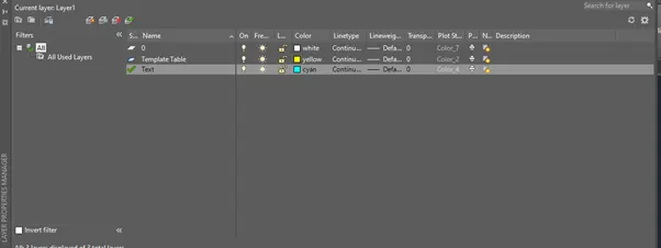
- The layers which are assigned are shown in below fig
- Set the current layer as Template Table
- Take a line command
- Specify first point > Anywhere in the drawing
- Specify next point > 300 > keeping the curser right side > enter
- Specify next point > 250 > keeping the curser upside > enter
- Take offset command
- Specify offset distance > 30
- Specfy object > Click on the horizontal line and take curser upside
- Specify offset distance > 20 > Enter
- Specify object as > Click on the last offset created line and take curser upside
- Specify offset distance > 35> Enter
- Specify object as > Click on the last offset created line and take curser upside
- Specify offset distance > 35 > Enter
- Specify object as > Click on the last offset created line and take curser upside
- Specify offset distance > 40 > Enter
- Specify object as > Click on the last offset created line and take curser upside
- Specify offset distance > 80 > Enter
- Specify object as > Click on the last offset created line and take curser upside
- Specify offset distance > 30 > Enter
- Specify object as > Click on the last offset created line and take curser upside
- Specify offset distance > 20 > Enter
- Specify object as > Click on the last offset created line and take curser upside
- Specify offset distance > 30 > Enter
- Specify object as > Click on the last offset created line and take curser upside
- Specify offset distance > 40 > Enter
- Specify object as > Click on the last offset created line and take curser upside
- Specify offset distance > 30 > Enter
- Specify object as > Click on the last offset created line and take curser upside
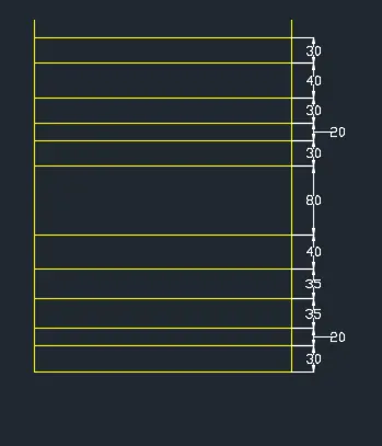
- It will gives you result as shown below
- Take offset command
- Specify offset distance > 60
- Specfy object > Click on the Right side vertical line and take curser Left side
- Specify offset distance > 20 > Enter
- Specify object as > Click on the last offset created line and take curser Left side
- Specify offset distance > 10 > Enter
- Specify object as > Click on the last offset created line and take curser Left side
- Specify offset distance > 50 > Enter
- Specify object as > Click on the last offset created line and take curser Left side
- Specify offset distance > 60 > Enter
- Specify object as > Click on the last offset created line and take curser Left side
- Specify offset distance > 50 > Enter
- Specify object as > Click on the last offset created line and take curser Left side
- Trim and erase the unwanted parts to create the table
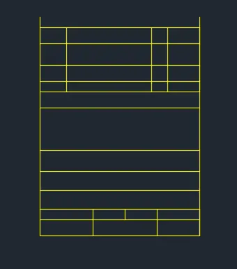
- The table is ready as shown below
- Change the current layer to text layer
- To create the text
- Click on Annotation tab >multi line
- Manage textile > New
- Style name as > Template 1 > OK
- Font Name > Arial
- Height > 7
- And press set current
- Use multiline text
- And fill the required text at required position
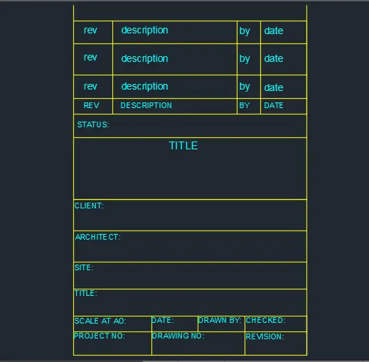
- The texts are as follows
- rev
- description
- by
- date
- REV
- DESCRIPTION
- BY
- DATE
- STATUS
- TITLE
- CLIENT
- ARCHITECT
- SITE
- TITLE etc.
- All the text can be placed in a proper position by using move command
- Select the title text and increase its size to 10
- The Template is ready as shown below
- Take block command by
- type B > enter
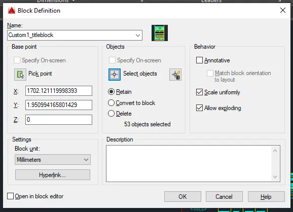
- dialogue box will be open
- Name > Custom1_titleblock
- Click on > Pick point
- Block specify insertion base point > click on any one corner of the table
- Select object > take a cross window and select whole template
- Block select object > enter
- Click on > Retain
- Scale uniformly > Mark it by clicking through curser
- Allow exploding > Mark it by clicking through curser as shown below
- Click on > Ok
- Enter
- The template is saved as a block
2. To Create Template 2 :
- Click on AutoCAD application and open this application
- Type QNEW in command bar and enter
- Select default setting as Metric
- In default setting click on use a wizard and in that advance setting and set unit as decimal and precision as 0 and press Next
- Set Angle as Decimal Degree and precision as 0 and click next
- Set Angle Measure as EAST and press NEXT
- Set Angle Direction as Counter-Clockwise and press NEXT
- Set Area by providing Length as 50 and Width as 50
- Press finish
- Keep ortho, Object snap >ON
- Keep Snap and Grid > Off
- Un+enter
- Type > Decimal, Precision > 0
- Units to scale inserted content > milimeter
- Enter
- Click on layer properties
- Click on new layer
- Give the layer name > Template Table
- Turn the layer ON
- Set Unlock
- Slect layer colour > Green
- Click on new layer
- Give the layer name > Text
- Turn the layer ON
- Set Unlock
- Slect layer colour > Cyan
- Click on new layer
- Give the layer name > Outline
- Turn the layer ON
- Set Unlock
- Slect layer colour > Red
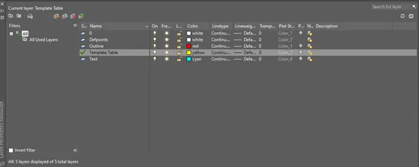
- The layers which are assigned are shown in below fig
- Set the current layer as outline layer
- Take a line command
- Specify first point > Anywhere in the drawing
- Specify next point > 1000 > keeping the curser right side > enter
- Specify next point > 300 > keeping the curser upside > enter
- Take offset command
- Specify offset distance > 75
- Specfy object > Click on the horizontal line and take curser upside
- Specify offset distance > 75 > Enter
- Specify object as > Click on the last offset created line and take curser upside
- Specify offset distance > 30> Enter
- Specify object as > Click on the last offset created line and take curser upside
- Specify offset distance > 30 > Enter
- Specify object as > Click on the last offset created line and take curser upside
- Specify offset distance > 50 > Enter
- Specify object as > Click on the last offset created line and take curser upside
- Specify offset distance > 30 > Enter
- Specify object as > Click on the last offset created line and take curser upside
- Take all these objects to the template table layer
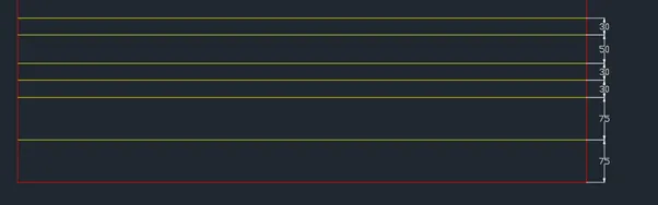
- It will gives you result as shown below
- Take offset command
- Specify offset distance > 60
- Specfy object > Click on the Right side vertical line and take curser Left side
- Specify offset distance > 40 > Enter
- Specify object as > Click on the last offset created line and take curser Left side
- Specify offset distance > 200 > Enter
- Specify object as > Click on the last offset created line and take curser Left side
- Specify offset distance > 50 > Enter
- Specify object as > Click on the last offset created line and take curser Left side
- Similarly take offset command and prepare the table as per requirement
- Trim and erase the unwanted parts to create the table
- The table is ready as shown below
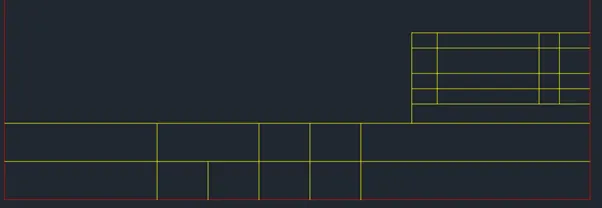
- Change the current layer to text layer
- To create the text
- Click on Annotation tab >multi line
- Manage textile > New
- Style name as > Template 2 > OK
- Font Name > Arial
- Height > 10
- And press set current
- Use multiline text
- And fill the required text at required position
- The texts are as follows
- REV
- DESCRIPTION
- BY
- DATE etc.
- All the text can be placed in a proper position by using move command
- As per requirement text height can be increased as shown below
- The Template is ready as shown below
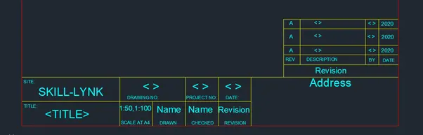
- Take block command by
- type B > enter
- dialogue box will be open
- Name > Custom2_titleblock
- Click on > Pick point
- Block specify insertion base point > click on any one corner of the table
- Select object > take a cross window and select whole template
- Block select object > enter
- Click on > Retain
- Scale uniformly > Mark it by clicking through curser
- Allow exploding > Mark it by clicking through curser as shown below
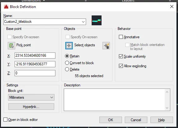
- Click on > Ok
- Enter
- The template is saved as a block
- RESULT :-
- TEMPLATE 1
- TEMPLATE 2
PROBLEM 2
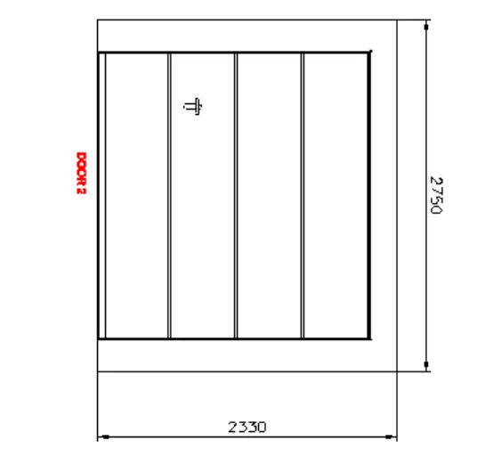
- Aim :- To create the Door1 and Door2 as shown below and save the respective door as a block.
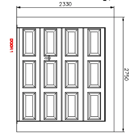
- Introduction :-
The general commands used for drawing the building is as follows :
- Line
- Polygon
- Rectangle
- Circle
- Erase
- Copy
- Trim
- Mirror
- Offset
- Extend
- Array
Etc.
- Procedure :-
1. To Create Door 1 :
- Click on AutoCAD application and open this application
- Type QNEW in command bar and enter
- Select default setting as Metric
- In default setting click on use a wizard and in that advance setting and set unit as decimal and precision as 0 and press Next
- Set Angle as Decimal Degree and precision as 0 and click next
- Set Angle Measure as EAST and press NEXT
- Set Angle Direction as Counter-Clockwise and press NEXT
- Set Area by providing Length as 50 and Width as 50
- Press finish
- Keep ortho, Object snap >ON
- Keep Snap and Grid > Off
- Un+enter
- Type > Decimal, Precision > 0
- Units to scale inserted content > milimeter
- Enter
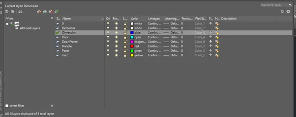
- Click on layer properties
- Click on new layer
- Give the layer name > Door frame
- Turn the layer ON
- Set Unlock
- Slect layer colour > Pink
- Click on new layer
- Give the layer name > Door Panel
- Turn the layer ON
- Set Unlock
- Slect layer colour > Green
- Give the layer name > Door
- Turn the layer ON
- Set Unlock
- Slect layer colour > Cyan
- Give the layer name > Handle
- Turn the layer ON
- Set Unlock
- Slect layer colour > Red
- Give the layer name > Door Panel
- Turn the layer ON
- Set Unlock
- Slect layer colour > Green
- The layers which are assigned are shown in below fig
- Set the current layer as door frame layer
- Take a line command
- Specify first point > Anywhere in the drawing
- Specify next point as > 2330 > enter by keeping curser rightside
- Specify next point as > 2750 > enter by keeping curser up side
- Specify next point as > 2330 > enter by keeping curser lrftside
- Specify next point as > 2750 > enter by keeping curser downside
- Take offset command
- Specify offset distance > 230
- Specfy object > Click on the bottom horizontal line and take curser upside
- Specify offset distance > 230
- Specfy object > Click on the top horizontal line and take curser down side
- Specify offset distance > 230
- Specfy object > Click on the upper right side vertical line and take curser left side
- Specify offset distance > 100
- Specfy object > Click on the left side vertical line and take curser upside
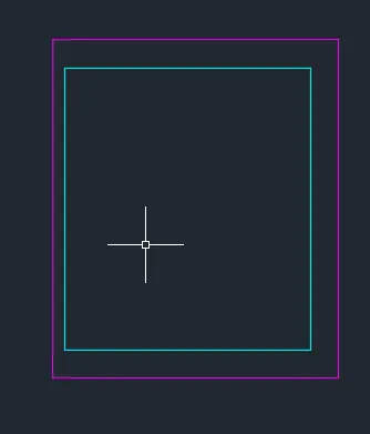
- Take all these offseted lines n the door layer
- Change current layer to door layer
- It will show us following result
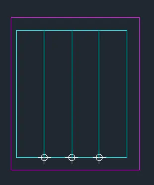
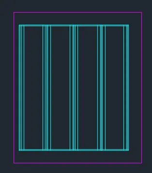
- Take divide command
- Select the object to divide > click on bottom horizontal line from the door layer
- Divide this line > 4 segment > enter
- Take the point style command
- Change the point style as to draw the line
- Take line command
- And draw the lines from all these nodes as shown below
- Again change the point style to the normal point style
- Take offset command
- Specify distance as 20
- Select object > select all these divide lines and offset these lines from both the sides
- Once againTake offset command
- Specify distance as 70
- Select object > select all these divide lines and offset these lines from both the sides
- Take divide command
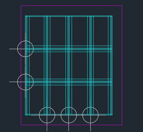
- Select the object to divide > click on left side verticalline from the door layer
- Divide this line > 3 segment > enter
- Take the point style command
- Change the point style as to draw the line
- Take line command
- And draw the lines from all these nodes as shown below
- Take offset command
- Specify distance as 20
- Select object > select all these divide lines and offset these lines from both the sides
- Once againTake offset command
- Specify distance as 70
- Select object > select all these divide lines and offset these lines from both the sides
- Change the point style to normal point style
- Change the current layer to panel layer
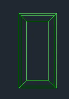
- Take rectangle command
- Specify corner point > anywhere
- Specify > dimension
- Length > 340, width > 680
- Enter
- Take offset command
- Specify distance as 20
- Select object > click on rectangle > enter keeping curser inwords
- Take offset command
- Specify distance as 50
- Select object > click on inner rectangle rectangle > enter keeping curser inwords
- Take a line command and join the corners as shown below
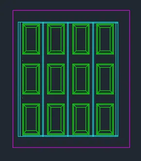
- Take the copy command
- Select object > select panel
- Specify base point > click on any corner of panel
- Place to a required positions as per drawing by keeping object snap ON
- Trim and erase all the unwanted lines as per shown below
- Change current layer to handle layer
- Take rectangle command
- Specify corner point > anywhere
- Click > dimension
- Length > 300, Width > 50
- Enter
- Take rectangle command
- Specify corner point > anywhere
- Click > dimension
- Length > 50, Width > 150
- Enter
- Take fillet option
- Multiple
- Use the fillet command to provide the arc at both the ends of rectangle
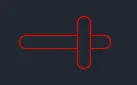
- Move the another rectangle and place in proper positon as it will show handle as shown below
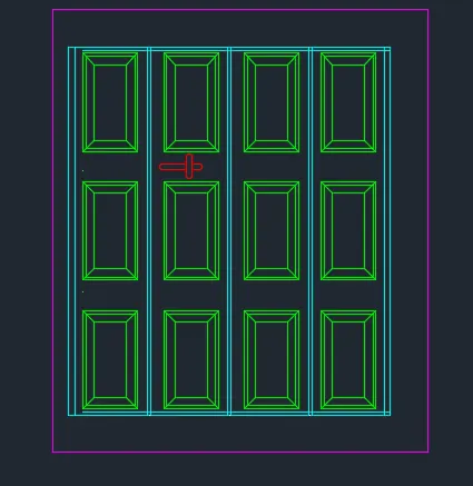
- Move the whole handle such as shown below
- Change the current layer to text layer
- To create the text
- Click on Annotation tab >multi line
- Manage textile > New
- Style name as > Door 1 > OK
- Font Name > Arial
- Height > 150
- And press set current
- Use multiline text
- And fill the required text at required position
- Click on ANNOTATION tab
- Click on Dimension
- Click > Manage dimension style
- Style name > Project
- Set the characteristics of dimensions as
- Select the yellow colour for the dimension style and extension line
- Select arrowhead size as 50
- Select the text as Cyan colour
- Select Text Style > Door 1
- Then select linear dimensions
- Provide the linear dimension
- And similarly this way, provide the dimensions wherever necessary as shown below
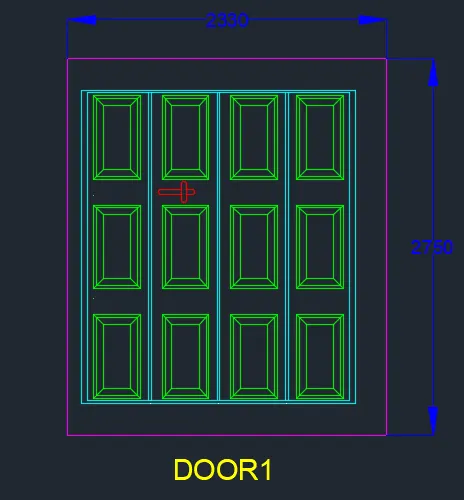
- Take block command by
- type B > enter
- dialogue box will be open
- Name > Door 1
- Click on > Pick point
- Block specify insertion base point > click on any one corner
- Select object > take a cross window and select whole drawing
- Block select object > enter
- Click on > Retain
- Scale uniformly > Mark it by clicking through curser
- Allow exploding > Mark it by clicking through curser as shown below
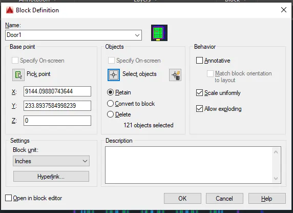
- Click on > Ok
- Enter
- The block is ready
2. To Create Door 2 :
- Click on AutoCAD application and open this application
- Type QNEW in command bar and enter
- Select default setting as Metric
- In default setting click on use a wizard and in that advance setting and set unit as decimal and precision as 0 and press Next
- Set Angle as Decimal Degree and precision as 0 and click next
- Set Angle Measure as EAST and press NEXT
- Set Angle Direction as Counter-Clockwise and press NEXT
- Set Area by providing Length as 50 and Width as 50
- Press finish
- Keep ortho, Object snap >ON
- Keep Snap and Grid > Off
- Un+enter
- Type > Decimal, Precision > 0
- Units to scale inserted content > milimeter
- Enter
- Click on layer properties
- Click on new layer
- Give the layer name > Door frame
- Turn the layer ON
- Set Unlock
- Slect layer colour > Pink
- Click on new layer
- Give the layer name > Door Panel
- Turn the layer ON
- Set Unlock
- Slect layer colour > Green
- Give the layer name > Door
- Turn the layer ON
- Set Unlock
- Slect layer colour > Cyan
- Give the layer name > Handle
- Turn the layer ON
- Set Unlock
- Slect layer colour > Red
- Give the layer name > Door Panel
- Turn the layer ON
- Set Unlock
- Slect layer colour > Green
- The layers which are assigned are shown in below fig
- Set the current layer as door frame layer
- Take a line command
- Specify first point > Anywhere in the drawing
- Specify next point as > 2330 > enter by keeping curser rightside
- Specify next point as > 2750 > enter by keeping curser up side
- Specify next point as > 2330 > enter by keeping curser lrftside
- Specify next point as > 2750 > enter by keeping curser downside
- Take offset command
- Specify offset distance > 230
- Specfy object > Click on the bottom horizontal line and take curser upside
- Specify offset distance > 230
- Specfy object > Click on the top horizontal line and take curser down side
- Specify offset distance > 230
- Specfy object > Click on the upper right side vertical line and take curser left side
- Specify offset distance > 100
- Specfy object > Click on the left side vertical line and take curser upside
- Take all these offseted lines n the door layer
- Change current layer to door layer
- It will show us following result
- Take divide command
- Select the object to divide > click on bottom horizontal line from the door layer
- Divide this line > 4 segment > enter
- Take the point style command
- Change the point style as to draw the line
- Take line command
- And draw the lines from all these nodes as shown below
- Again change the point style to the normal point style
- Take offset command
- Specify distance as 20
- Select object > select all these divide lines and offset these lines from both the sides
- Once againTake offset command
- Specify distance as 70
- Select object > select all these divide lines and offset these lines from both the sides
- Trim and erase all the unwanted lines as per shown below
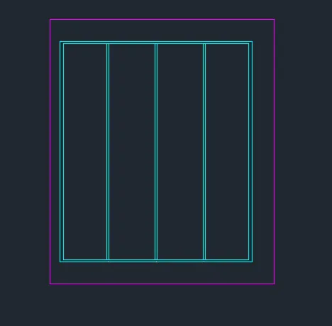
- Change current layer to handle layer
- Take rectangle command
- Specify corner point > anywhere
- Click > dimension
- Length > 300, Width > 50
- Enter
- Take rectangle command
- Specify corner point > anywhere
- Click > dimension
- Length > 50, Width > 150
- Enter
- Take fillet option
- Multiple
- Use the fillet command to provide the arc at both the ends of rectangle
- Move the another rectangle and place in proper positon as it will show handle as shown below
- Move the whole handle such as shown below
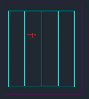
- Change the current layer to text layer
- To create the text
- Click on Annotation tab >multi line
- Manage textile > New
- Style name as > Door 2 > OK
- Font Name > Arial
- Height > 150
- And press set current
- Use multiline text
- And fill the required text at required position
- Click on ANNOTATION tab
- Click on Dimension
- Click > Manage dimension style
- Style name > Project
- Set the characteristics of dimensions as
- Select the yellow colour for the dimension style and extension line
- Select arrowhead size as 50
- Select the text as Cyan colour
- Select Text Style > Door 2
- Then select linear dimensions
- Provide the linear dimension
- And similarly this way, provide the dimensions wherever necessary as shown below
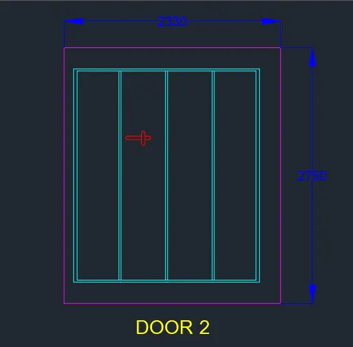
- Take block command by
- type B > enter
- dialogue box will be open
- Name > Door 2
- Click on > Pick point
- Block specify insertion base point > click on any one corner
- Select object > take a cross window and select whole drawing
- Block select object > enter
- Click on > Retain
- Scale uniformly > Mark it by clicking through curser
- Allow exploding > Mark it by clicking through curser as shown below
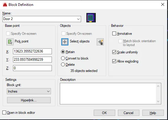
- Click > Ok
- The block is ready
- Result :
- Door 1 :
- Door 2:
PROBLEM 3
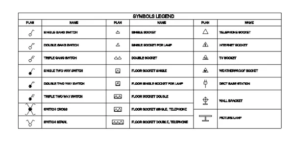
- Aim :- To Create each symbol as a block and after creating the blocks arrange them in the legend as shown in the Figure.
- Introduction :-
The general commands used for drawing the building is as follows :
- Line
- Polygon
- Rectangle
- Circle
- Erase
- Copy
- Trim
- Mirror
- Offset
- Extend
- Array
- Move
- Rotate
- Dimension
- Text
- Fillet
Etc.
- Procedure :-
- Click on AutoCAD application and open this application
- Type QNEW in command bar and enter
- Select default setting as Metric
- In default setting click on use a wizard and in that advance setting and set unit as decimal and precision as 0 and press Next
- Set Angle as Decimal Degree and precision as 0 and click next
- Set Angle Measure as EAST and press NEXT
- Set Angle Direction as Counter-Clockwise and press NEXT
- Set Area by providing Length as 50 and Width as 50
- Press finish
- Keep ortho, Object snap >ON
- Keep Snap and Grid > Off
- Un+enter
- Type > Decimal, Precision > 0
- Units to scale inserted content > milimeter
- Enter
- Click on layer properties
- Click on new layer
- Give the layer name > Legend Table
- Turn the layer ON
- Set Unlock
- Slect layer colour > Green
- Click on new layer
- Give the layer name > Text
- Turn the layer ON
- Set Unlock
- Slect layer colour > Cyan
- Click on new layer
- Give the layer name > Block Name
- Turn the layer ON
- Set Unlock
- Slect layer colour > Black
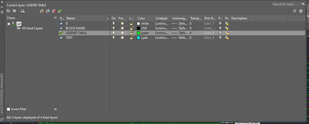
- The layers which are assigned are shown in below fig
- Set the current layer as legend table layer
- Take a line command
- Specify first point > Anywhere in the drawing
- Specify next point as > 250 > enter by keeping curser rightside
- Specify next point as > 84 > enter by keeping curser up side
- Specify next point as > 250 > enter by keeping curser leftside
- Specify next point as > 84 > enter by keeping curser downside
- Take offset command
- Specify offset distance > 9
- Specfy object > Click on the bottom horizontal line and take curser upside
- Specify offset distance > 18
- Specfy object > Click on the bottom horizontal line and take curser upside
- Specify offset distance > 27
- Specfy object > Click on the bottom horizontal line and take curser upside
- Specify offset distance > 36
- Specfy object > Click on the bottom horizontal line and take curser upside
- Specify offset distance > 45
- Specfy object > Click on the bottom horizontal line and take curser upside
- Specify offset distance > 54
- Specfy object > Click on the bottom horizontal line and take curser upside
- Specify offset distance > 63
- Specfy object > Click on the bottom horizontal line and take curser upside
- Specify offset distance > 72
- Specfy object > Click on the bottom horizontal line and take curser upside
- Specify offset distance > 77
- Specfy object > Click on the bottom horizontal line and take curser upside
- Specify offset distance > 84
- Specfy object > Click on the bottom horizontal line and take curser upside
- Specify offset distance > 15
- Specfy object > Click on the left vertical line and take curser right side
- Specify offset distance > 75
- Specfy object > Click on the left vertical line and take curser right side
- Specify offset distance > 90
- Specfy object > Click on the left vertical line and take curser right side
- Specify offset distance > 150
- Specfy object > Click on the left vertical line and take curser right side
- Specify offset distance > 165
- Specfy object > Click on the left vertical line and take curser right side
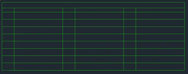
- It will shows us following result
- To create block, change the layer
- Single Gang Switch :
- Use the line command and circle command to draw the single gang switch as shown below

- To create block
- Type b in command bar > enter
- dialogue box will be open
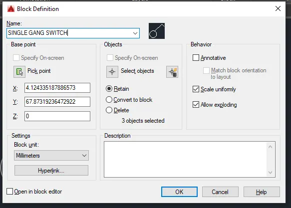
- Name > SINGLE GANG SWITCH
- Click on > Pick point
- Block specify insertion base point > click on centre of circle
- Select object > take a cross window and select whole drawing
- Block select object > enter
- Click on > Retain
- Scale uniformly > Mark it by clicking through curser
- Allow exploding > Mark it by clicking through curser as shown below
- Press > OK
- Block is ready
- Double Gang Switch
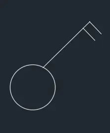
- Use the line command and circle command to draw the Double Gang Switch as shown below
- To create block
- Type b in command bar > enter
- dialogue box will be open
- Name > DOUBLE GANG SWITCH
- Click on > Pick point
- Block specify insertion base point > click on centre of circle
- Select object > take a cross window and select whole drawing
- Block select object > enter
- Click on > Retain
- Scale uniformly > Mark it by clicking through curser
- Allow exploding > Mark it by clicking through curser as shown below
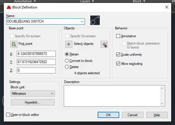
- Press > OK
- Block is ready
- Triple Gang Switch
- Use the line command and circle command to draw the Double Gang Switch as shown below

- To create block
- Type b in command bar > enter
- dialogue box will be open
- Name > TRIPLE GANG SWITCH
- Click on > Pick point
- Block specify insertion base point > click on centre of circle
- Select object > take a cross window and select whole drawing
- Block select object > enter
- Click on > Retain
- Scale uniformly > Mark it by clicking through curser
- Allow exploding > Mark it by clicking through curser as shown below
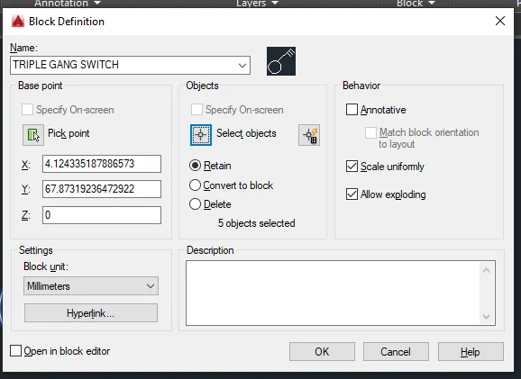
- Press > OK
- Block is ready
- By this similar way , draw all the following blocks
- Single Two way switch
- Double Two way switch
- Triple Two way switch
- Switch Cross
- Switch Serial
- Sngle Socket
- Single Socket for lamp
- Double Socket
- Floor Socket Single
- Floor Single Socket for Lamp
- Floor Socket Double
- Floor Socket Single Telephone
- Floor Socket Double Telephone
- Teliphone Socket
- Internet Socket
- TV Socket
- Weather Proof Socket
- Dect Base Station
- Wall Bracket
- Picture Lamp
- Change the current layer to text layer
- To create the text
- Click on Annotation tab >multi line
- Manage textile > New
- Style name as > LEGEND > OK
- Font Name > Arial
- Height > 3
- And press set current
- Use multiline text
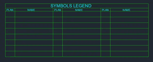
- And fill the required text at required position
- For SYMBOLS LEGEND, take text height as 5
- It will give us following result
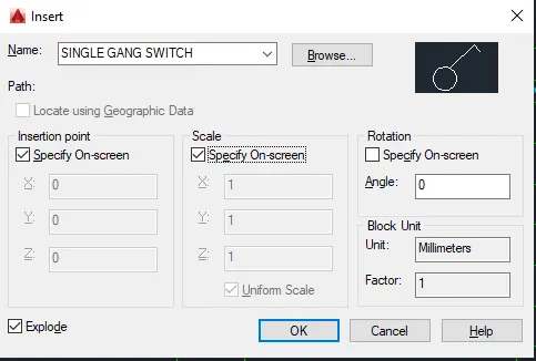
- Take insert command
- Click on drop down
- Select the block which you want to tshow in legend
- Do the setting as per convineance
- Following picture shows the settings I have made
- Press > OK
- Specify insertion point for block
- Then
- After inserting the block
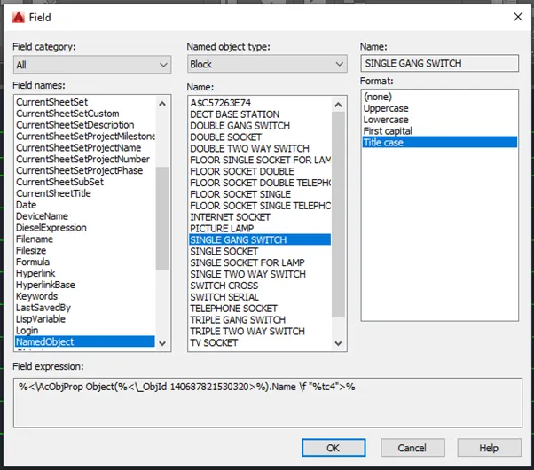
- Insert the block name by
- Click on insert > Field
- It will open a dialogue box
- In dialogue box select field name > Named Object
- Select Name > Single Gang Switch
- Format > Title Case as shown below
- Press OK
- Similarly Insert all the block name using the similar procedure
- It will shows the following result
- The legend is ready
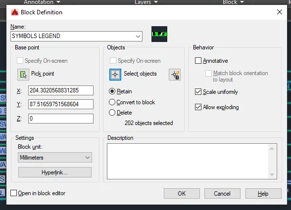
- To create block
- Type b in command bar > enter
- dialogue box will be open
- Name > TRIPLE GANG SWITCH
- Click on > Pick point
- Block specify insertion base point > click on centre of circle
- Select object > take a cross window and select whole drawing
- Block select object > enter
- Click on > Retain
- Scale uniformly > Mark it by clicking through curser
- Allow exploding > Mark it by clicking through curser as shown below
- Press Ok
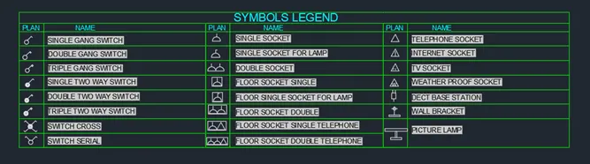
- The legend with block is ready
- RESULT :-
PROBLEM 4
- Aim :- To Create the door type for residential building as a block and Save the name of the blocks as type.
- Introduction :-
The general commands used for drawing the building is as follows :
- Line
- Polygon
- Rectangle
- Circle
- Erase
- Copy
- Trim
- Mirror
- Offset
- Extend
- Array
- Move
- Rotate
- Dimension
- Text
- Fillet
Etc.
- Procedure :-
1. To Create Door 1 :
- Click on AutoCAD application and open this application
- Type QNEW in command bar and enter
- Select default setting as Imperial
- In default setting click on use a wizard and in that advance setting and set unit as Engineering and precision as 0’0.0” and press Next
- Set Angle as Decimal Degree and precision as 0 and click next
- Set Angle Measure as EAST and press NEXT
- Set Angle Direction as Counter-Clockwise and press NEXT
- Set Area by providing Length as 50 and Width as 50
- Press finish
- Keep ortho, Object snap >ON
- Keep Snap and Grid > Off
- Un+enter
- Type > Decimal, Precision > 0’0.0”
- Units to scale inserted content > inches
- Enter
- Click on layer properties
- Click on new layer
- Give the layer name > Door layer
- Turn the layer ON
- Set Unlock
- Slect layer colour > Yellow
- Click on new layer
- Give the layer name > handle
- Turn the layer ON
- Set Unlock
- Slect layer colour > Green
- The layers which are assigned are shown in below fig
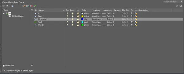
- Set the current layer as Template Table
- Take a line command
- Specify first point > Anywhere in the drawing
- Specify next point > 2’10” > keeping the curser right side > enter
- Specify next point > 6’11” > keeping the curser upside > enter
- Specify next point > 2’10” > keeping the curser left side > enter
- Specify next point > 6’11” > keeping the curser down side > enter
- Take offset command
- Specify offset distance > 2” > Enter
- Specify object as > Click on the Left side vertical line and take curser rightside
- Specify offset distance > 2”> Enter
- Specify object as > Click on the last offset created line and take curser rightside
- Specify offset distance > 2” > Enter
- Specify object as > Click on the right side vertical line and take curser leftside
- Specify offset distance > 2”> Enter
- Specify object as > Click on the last offset created line and take curser leftside
- Specify offset distance > 2” > Enter
- Specify object as > Click on the top horizontal line and take curser down side
- Specify offset distance > 2”> Enter
- Specify object as > Click on the last offset created line and take curser downside
- Change the current layer to handle layer
- Use the rectangle and circle command to show the door handle
- Change the current layer to text layer
- To create the text
- Click on Annotation tab >multi line
- Manage textile > New
- Style name as > D1 > OK
- Font Name > Arial
- Height > 3
- And press set current
- Use multiline text
- And fill the required text at required position
- Click on ANNOTATION tab
- Click on Dimension
- Click > Manage dimension style
- Style name > D1
- Set the characteristics of dimensions as
- Select the yellow colour for the dimension style and extension line
- Select arrowhead size as 3”
- Select the text as Cyan colour
- Select Text Style > Door 1
- Then select linear dimensions
- Provide the linear dimension
- And similarly this way, provide the dimensions wherever necessary as shown below
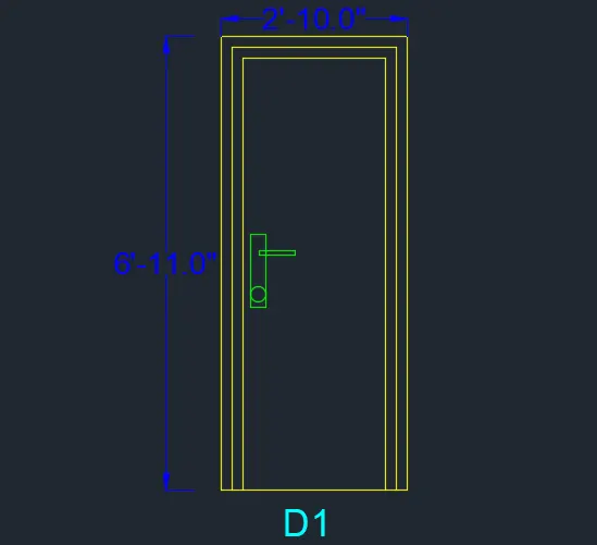
- To create block
- Type b in command bar > enter
- dialogue box will be open
- Name > Door 1
- Click on > Pick point
- Block specify insertion base point > click on centre of circle
- Select object > take a cross window and select whole drawing
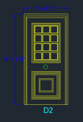
- Block select object > enter
- Click on > Retain
- Scale uniformly > Mark it by clicking through curser
- Allow exploding > Mark it by clicking through curser as shown below
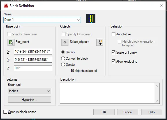
- Press > Ok
- The block is ready
2. To Create Door 2 :
- Click on AutoCAD application and open this application
- Type QNEW in command bar and enter
- Select default setting as Imperial
- In default setting click on use a wizard and in that advance setting and set unit as Engineering and precision as 0’0.0” and press Next
- Set Angle as Decimal Degree and precision as 0 and click next
- Set Angle Measure as EAST and press NEXT
- Set Angle Direction as Counter-Clockwise and press NEXT
- Set Area by providing Length as 50 and Width as 50
- Press finish
- Keep ortho, Object snap >ON
- Keep Snap and Grid > Off
- Un+enter
- Type > Decimal, Precision > 0’0.0”
- Units to scale inserted content > inches
- Enter
- Click on layer properties
- Click on new layer
- Give the layer name > Door layer
- Turn the layer ON
- Set Unlock
- Slect layer colour > Yellow
- Click on new layer
- Give the layer name > handle
- Turn the layer ON
- Set Unlock
- Slect layer colour > Green
- The layers which are assigned are shown in below fig
- Set the current layer as Template Table
- Take a line command
- Specify first point > Anywhere in the drawing
- Specify next point > 3’4” > keeping the curser right side > enter
- Specify next point > 6’11” > keeping the curser upside > enter
- Specify next point > 3’4” > keeping the curser left side > enter
- Specify next point > 6’11” > keeping the curser down side > enter
- Take offset command
- And provide the offset as per requirement as shown below
- Change the current layer to handle layer
- Use the circle command to show the door handle
- Change the current layer to text layer
- To create the text
- Click on Annotation tab >multi line
- Manage textile > New
- Style name as > D2 > OK
- Font Name > Arial
- Height > 3
- And press set current
- Use multiline text
- And fill the required text at required position
- Click on ANNOTATION tab
- Click on Dimension
- Click > Manage dimension style
- Style name > D2
- Set the characteristics of dimensions as
- Select the yellow colour for the dimension style and extension line
- Select arrowhead size as 3”
- Select the text as Cyan colour
- Select Text Style > Door 2
- Then select linear dimensions
- Provide the linear dimension
- And similarly this way, provide the dimensions wherever necessary as shown below
- To create block
- Type b in command bar > enter
- dialogue box will be open
- Name > Door 2
- Click on > Pick point
- Block specify insertion base point > click on centre of circle
- Select object > take a cross window and select whole drawing
- Block select object > enter
- Click on > Retain
- Scale uniformly > Mark it by clicking through curser
- Allow exploding > Mark it by clicking through curser as shown below
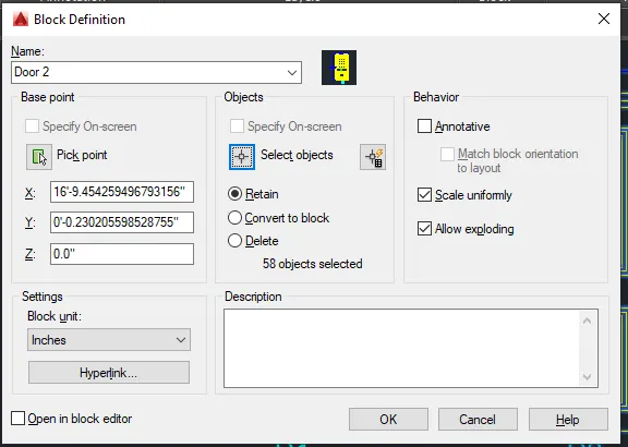
- Press > OK
- The block is ready
3. To Create Door 3 :
- Click on AutoCAD application and open this application
- Type QNEW in command bar and enter
- Select default setting as Imperial
- In default setting click on use a wizard and in that advance setting and set unit as Engineering and precision as 0’0.0” and press Next
- Set Angle as Decimal Degree and precision as 0 and click next
- Set Angle Measure as EAST and press NEXT
- Set Angle Direction as Counter-Clockwise and press NEXT
- Set Area by providing Length as 50 and Width as 50
- Press finish
- Keep ortho, Object snap >ON
- Keep Snap and Grid > Off
- Un+enter
- Type > Decimal, Precision > 0’0.0”
- Units to scale inserted content > inches
- Enter
- Click on layer properties
- Click on new layer
- Give the layer name > Door layer
- Turn the layer ON
- Set Unlock
- Slect layer colour > Yellow
- Click on new layer
- Give the layer name > handle
- Turn the layer ON
- Set Unlock
- Slect layer colour > Green
- The layers which are assigned are shown in below fig
- Set the current layer as Template Table
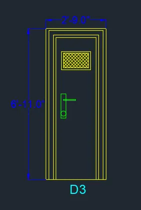
- Take a line command
- Specify first point > Anywhere in the drawing
- Specify next point > 2’9” > keeping the curser right side > enter
- Specify next point > 6’11” > keeping the curser upside > enter
- Specify next point > 2’9” > keeping the curser left side > enter
- Specify next point > 6’11” > keeping the curser down side > enter
- Take offset command
- And provide the offset as per requirement as shown below
- Change the current layer to handle layer
- Use the rectangle command and circle command to show the door handle
- Change the current layer to text layer
- To create the text
- Click on Annotation tab >multi line
- Manage textile > New
- Style name as > D3 > OK
- Font Name > Arial
- Height > 3
- And press set current
- Use multiline text
- And fill the required text at required position
- Click on ANNOTATION tab
- Click on Dimension
- Click > Manage dimension style
- Style name > D3
- Set the characteristics of dimensions as
- Select the yellow colour for the dimension style and extension line
- Select arrowhead size as 3”
- Select the text as Cyan colour
- Select Text Style > Door 3
- Then select linear dimensions
- Provide the linear dimension
- And similarly this way, provide the dimensions wherever necessary as shown below
- To create block
- Type b in command bar > enter
- dialogue box will be open
- Name > Door 3
- Click on > Pick point
- Block specify insertion base point > click on centre of circle
- Select object > take a cross window and select whole drawing
- Block select object > enter
- Click on > Retain
- Scale uniformly > Mark it by clicking through curser
- Allow exploding > Mark it by clicking through curser as shown below
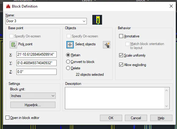
- Click > OK
- The block is ready
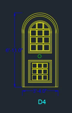
4. To Create Door 4 :
- Click on AutoCAD application and open this application
- Type QNEW in command bar and enter
- Select default setting as Imperial
- In default setting click on use a wizard and in that advance setting and set unit as Engineering and precision as 0’0.0” and press Next
- Set Angle as Decimal Degree and precision as 0 and click next
- Set Angle Measure as EAST and press NEXT
- Set Angle Direction as Counter-Clockwise and press NEXT
- Set Area by providing Length as 50 and Width as 50
- Press finish
- Keep ortho, Object snap >ON
- Keep Snap and Grid > Off
- Un+enter
- Type > Decimal, Precision > 0’0.0”
- Units to scale inserted content > inches
- Enter
- Click on layer properties
- Click on new layer
- Give the layer name > Door layer
- Turn the layer ON
- Set Unlock
- Slect layer colour > Yellow
- Click on new layer
- Give the layer name > handle
- Turn the layer ON
- Set Unlock
- Slect layer colour > Green
- The layers which are assigned are shown in below fig
- Set the current layer as Template Table
- Take a line command
- Specify first point > Anywhere in the drawing
- Specify next point > 3’4” > keeping the curser right side > enter
- Specify next point > 6’11” > keeping the curser upside > enter
- Specify next point > 3’4” > keeping the curser left side > enter
- Specify next point > 6’11” > keeping the curser down side > enter
- Take offset command
- And provide the offset as per requirement and also use the arc command as shown below
- Change the current layer to handle layer
- Use the circle command to show the door handle
- Change the current layer to text layer
- To create the text
- Click on Annotation tab >multi line
- Manage textile > New
- Style name as > D4 > OK
- Font Name > Arial
- Height > 3
- And press set current
- Use multiline text
- And fill the required text at required position
- Click on ANNOTATION tab
- Click on Dimension
- Click > Manage dimension style
- Style name > D4
- Set the characteristics of dimensions as
- Select the yellow colour for the dimension style and extension line
- Select arrowhead size as 3”
- Select the text as Cyan colour
- Select Text Style > Door 4
- Then select linear dimensions
- Provide the linear dimension
- And similarly this way, provide the dimensions wherever necessary as shown below
- To create block
- Type b in command bar > enter
- dialogue box will be open
- Name > Door 4
- Click on > Pick point
- Block specify insertion base point > click on centre of circle
- Select object > take a cross window and select whole drawing
- Block select object > enter
- Click on > Retain
- Scale uniformly > Mark it by clicking through curser
- Allow exploding > Mark it by clicking through curser as shown below
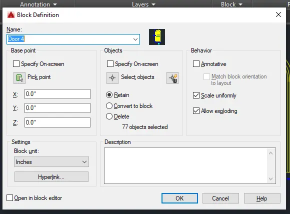
- Press > OK
- The block is ready
5. To Create Door 5 :
- Click on AutoCAD application and open this application
- Type QNEW in command bar and enter
- Select default setting as Imperial
- In default setting click on use a wizard and in that advance setting and set unit as Engineering and precision as 0’0.0” and press Next
- Set Angle as Decimal Degree and precision as 0 and click next
- Set Angle Measure as EAST and press NEXT
- Set Angle Direction as Counter-Clockwise and press NEXT
- Set Area by providing Length as 50 and Width as 50
- Press finish
- Keep ortho, Object snap >ON
- Keep Snap and Grid > Off
- Un+enter
- Type > Decimal, Precision > 0’0.0”
- Units to scale inserted content > inches
- Enter
- Click on layer properties
- Click on new layer
- Give the layer name > Door layer
- Turn the layer ON
- Set Unlock
- Slect layer colour > Yellow
- Click on new layer
- Give the layer name > handle
- Turn the layer ON
- Set Unlock
- Slect layer colour > Green
- The layers which are assigned are shown in below fig
- Set the current layer as Template Table
- Take a line command
- Specify first point > Anywhere in the drawing
- Specify next point > 3’4” > keeping the curser right side > enter
- Specify next point > 6’11” > keeping the curser upside > enter
- Specify next point > 3’4” > keeping the curser left side > enter
- Specify next point > 6’11” > keeping the curser down side > enter
- Take offset command
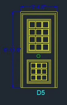
- And provide the offset as per requirement and rectangle command as shown below
- Change the current layer to handle layer
- Use the circle command to show the door handle
- Change the current layer to text layer
- To create the text
- Click on Annotation tab >multi line
- Manage textile > New
- Style name as > D5 > OK
- Font Name > Arial
- Height > 3
- And press set current
- Use multiline text
- And fill the required text at required position
- Click on ANNOTATION tab
- Click on Dimension
- Click > Manage dimension style
- Style name > D5
- Set the characteristics of dimensions as
- Select the yellow colour for the dimension style and extension line
- Select arrowhead size as 3”
- Select the text as Cyan colour
- Select Text Style > Door 5
- Then select linear dimensions
- Provide the linear dimension
- And similarly this way, provide the dimensions wherever necessary as shown below
- To create block
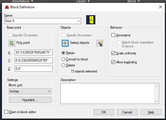
- Type b in command bar > enter
- dialogue box will be open
- Name > Door 5
- Click on > Pick point
- Block specify insertion base point > click on centre of circle
- Select object > take a cross window and select whole drawing
- Block select object > enter
- Click on > Retain
- Scale uniformly > Mark it by clicking through curser
- Allow exploding > Mark it by clicking through curser as shown below
- Press > Ok
- The block is ready
6. To Create Door 6 :
- Click on AutoCAD application and open this application
- Type QNEW in command bar and enter
- Select default setting as Imperial
- In default setting click on use a wizard and in that advance setting and set unit as Engineering and precision as 0’0.0” and press Next
- Set Angle as Decimal Degree and precision as 0 and click next
- Set Angle Measure as EAST and press NEXT
- Set Angle Direction as Counter-Clockwise and press NEXT
- Set Area by providing Length as 50 and Width as 50
- Press finish
- Keep ortho, Object snap >ON
- Keep Snap and Grid > Off
- Un+enter
- Type > Decimal, Precision > 0’0.0”
- Units to scale inserted content > inches
- Enter
- Click on layer properties
- Click on new layer
- Give the layer name > Door layer
- Turn the layer ON
- Set Unlock
- Slect layer colour > Yellow
- Click on new layer
- Give the layer name > handle
- Turn the layer ON
- Set Unlock
- Slect layer colour > Green
- The layers which are assigned are shown in below fig
- Set the current layer as Template Table
- Take a line command
- Specify first point > Anywhere in the drawing
- Specify next point > 3’4” > keeping the curser right side > enter
- Specify next point > 6’11” > keeping the curser upside > enter
- Specify next point > 3’4” > keeping the curser left side > enter
- Specify next point > 6’11” > keeping the curser down side > enter
- Take offset command
- And provide the offset as per requirement and rectangle command as shown below
- Change the current layer to handle layer
- Use the circle command to show the door handle
- Change the current layer to text layer
- To create the text
- Click on Annotation tab >multi line
- Manage textile > New
- Style name as > D5 > OK
- Font Name > Arial
- Height > 3
- And press set current
- Use multiline text
- And fill the required text at required position
- Click on ANNOTATION tab
- Click on Dimension
- Click > Manage dimension style
- Style name > D5
- Set the characteristics of dimensions as
- Select the yellow colour for the dimension style and extension line
- Select arrowhead size as 3”
- Select the text as Cyan colour
- Select Text Style > Door 5
- Then select linear dimensions
- Provide the linear dimension
- And similarly this way, provide the dimensions wherever necessary as shown below
- To create block
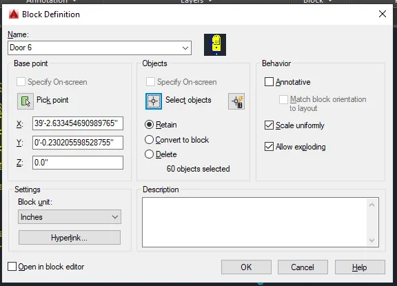
- Type b in command bar > enter
- dialogue box will be open
- Name > Door 5
- Click on > Pick point
- Block specify insertion base point > click on centre of circle
- Select object > take a cross window and select whole drawing
- Block select object > enter
- Click on > Retain
- Scale uniformly > Mark it by clicking through curser
- Allow exploding > Mark it by clicking through curser as shown below
- Press > OK
- The block is ready
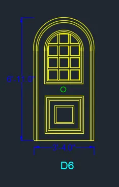
- RESULT :-
- D1
- D2
- D3
- D4
- D5
- D6
PROBLEM 4
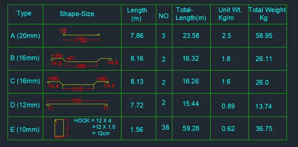
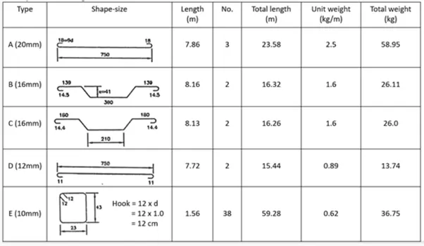
- Aim :- To Create the block of each reinforcement and insert that block in table as shown below to create the Bar Bending Schedule
- Introduction :-
The general commands used for drawing the building is as follows :
- Line
- Polygon
- Rectangle
- Circle
- Erase
- Copy
- Trim
- Mirror
- Offset
- Extend
- Array
- Move
- Rotate
- Dimension
- Text
- Fillet
etc
- Procedure :-
- Click on AutoCAD application and open this application
- Type QNEW in command bar and enter
- Select default setting as Metric
- In default setting click on use a wizard and in that advance setting and set unit as decimal and precision as 0 and press Next
- Set Angle as Decimal Degree and precision as 0 and click next
- Set Angle Measure as EAST and press NEXT
- Set Angle Direction as Counter-Clockwise and press NEXT
- Set Area by providing Length as 50 and Width as 50
- Press finish
- Keep ortho, Object snap >ON
- Keep Snap and Grid > Off
- Un+enter
- Type > Decimal, Precision > 0
- Units to scale inserted content > Centimeter
- Enter
- Click on layer properties
- Click on new layer
- Give the layer name > Table
- Turn the layer ON
- Set Unlock
- Slect layer colour > Green
- Similarly provide all the layers
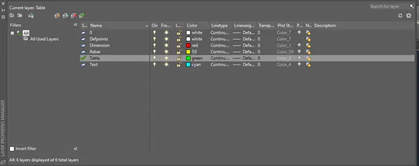
- The layers which are assigned are shown in below fig
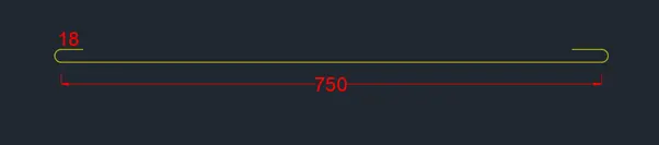
- To create the block for rebar Type A
- Take a line command
- Specify first point > Anywhere in the drawing
- Specify next point as > 750 > enter by keeping curser rightside
- Enter
- Use the circle command to show bend
- To create block for this
- Type b in command bar > enter
- dialogue box will be open
- Name > Door 5
- Click on > Pick point
- Block specify insertion base point > click on centre of circle
- Select object > take a cross window and select whole drawing
- Block select object > enter
- Click on > Retain
- Scale uniformly > Mark it by clicking through curser
- Allow exploding > Mark it by clicking through curser as shown below
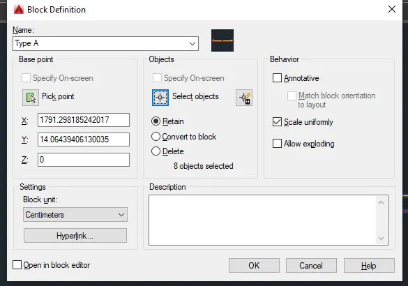
- Press > Ok
- The block for Type A is ready
- Similarly do the block for Type B, Type C, Type D and Type E
- Change the current layer to table layer
- Draw the table by using line and offset command
- Change the current layer to text layer
- To create the text
- Click on Annotation tab >multi line
- Manage textile > New
- Style name as > D5 > OK
- Font Name > Arial
- Height > 3
- And press set current
- Use multiline text
- And fill the required text at required position
- To insert the blocks created
- Take insert command
- Select the block
- And do settings as per convineance
- And specify the insertion point to locate the block position
- Enter
- Click on ANNOTATION tab
- Click on Dimension
- Click > Manage dimension style
- Style name > D5
- Set the characteristics of dimensions as
- Select the yellow colour for the dimension style and extension line
- Select arrowhead size as 3”
- Select the text as Cyan colour
- Select Text Style > Door 5
- Then select linear dimensions
- Provide the linear dimension
- And similarly this way, provide the dimensions wherever necessary as shown below
- The bar bending schedule is ready
- RESULT :-