Creating Bar Bending schedule, Different Door types, and Creation of standard drawing templates using AutoCad
ANSWERS FOR CHALLENGE
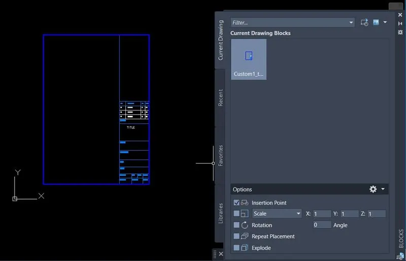
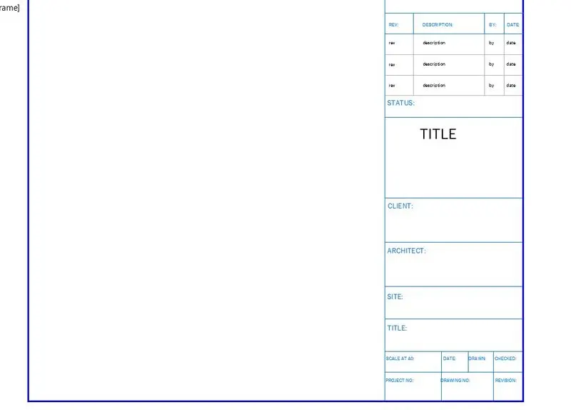
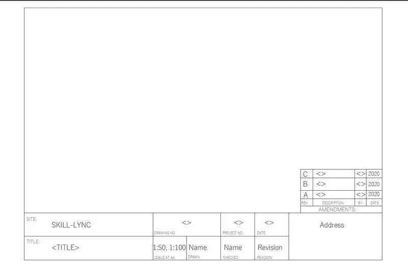
1. Create the templates as shown in Figures. Take the size of the title block as per industry standards or you can assume it as per the size of the paper. Use text and attributes wherever required. After creating the title block you need to save it as a block with names: Custom1_titleblock and Custom2_titleblock, respectively.
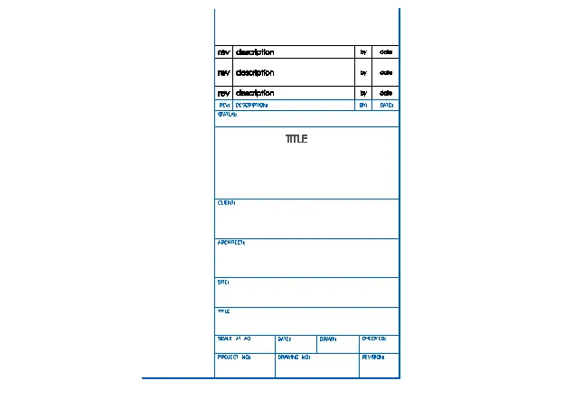
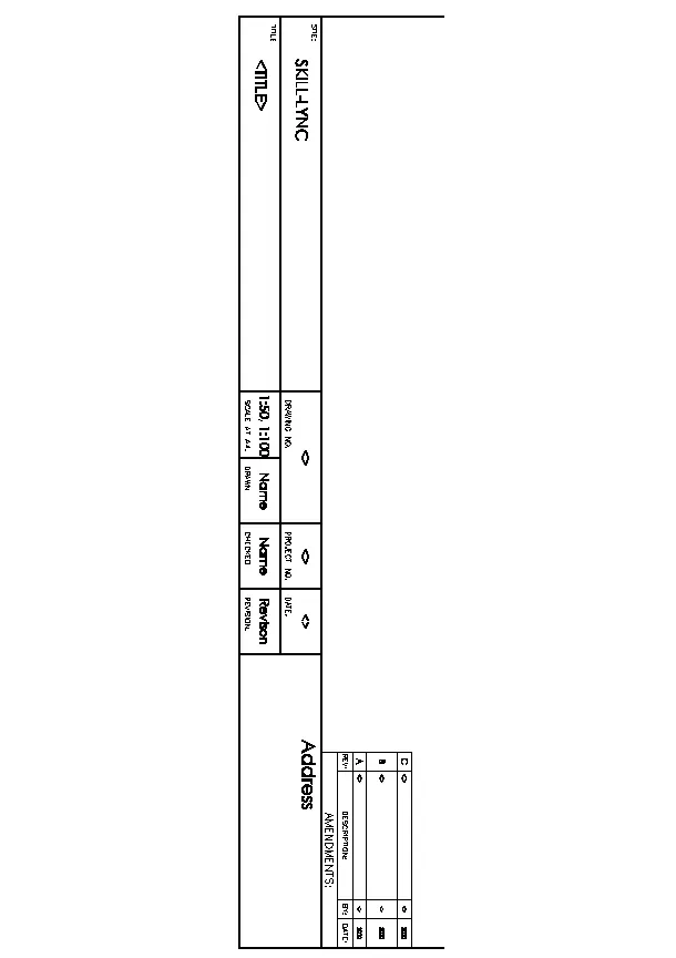
1.Ans:
AIM:- To creating the template and blocked with named as Custom1_titleblock and Custom2_titleblock, respectively.
PROCEDURE:-
For Custom1_titleblock template:
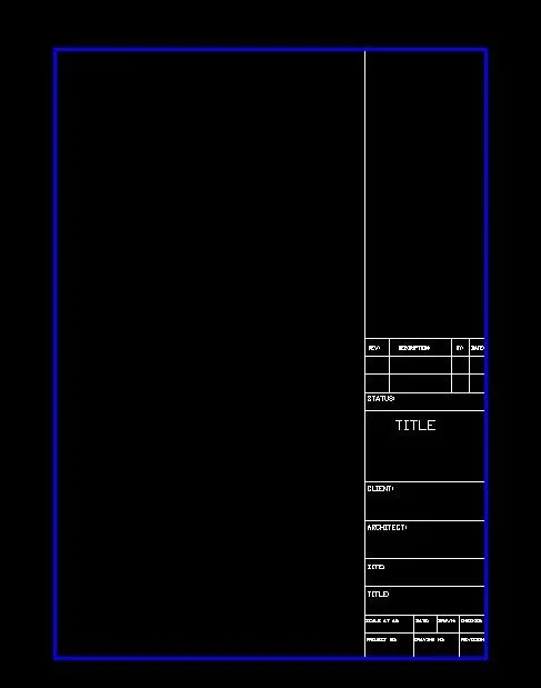
- For the first bolck draw a rectangle of the size (841 X 1189 mm) as it is the standard size of the A0 size paper.
- Now explode the rectangle so that we can work on each line separetly.
- Now give offset of 235 mm from right to left to create a title box.
- Now give offset to the horizontal lines to create boxes of the desired size.
- Now trim the excess lines and then the format of the title block is ready.
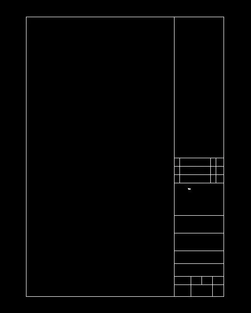
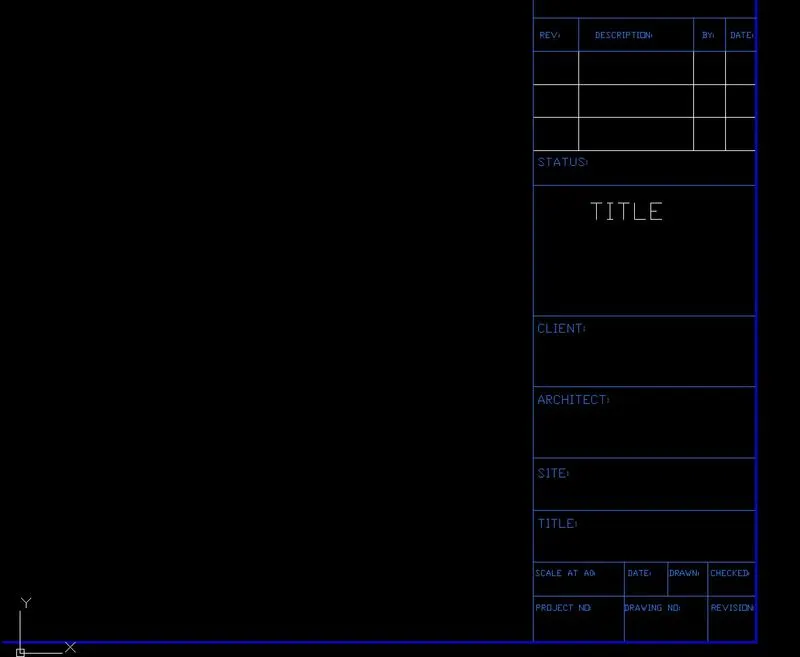
- Now as the sheet format is ready use the "DTEXT" of the desired/Preffered size to notate the boxes for what they are going to used for.
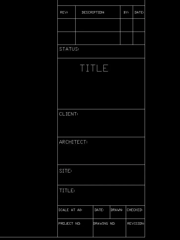
- Now change the colour of template boundary line and creating new layer as boundary.
- Then creating new layer named as Text and applying the new colour to it.
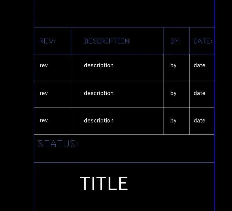
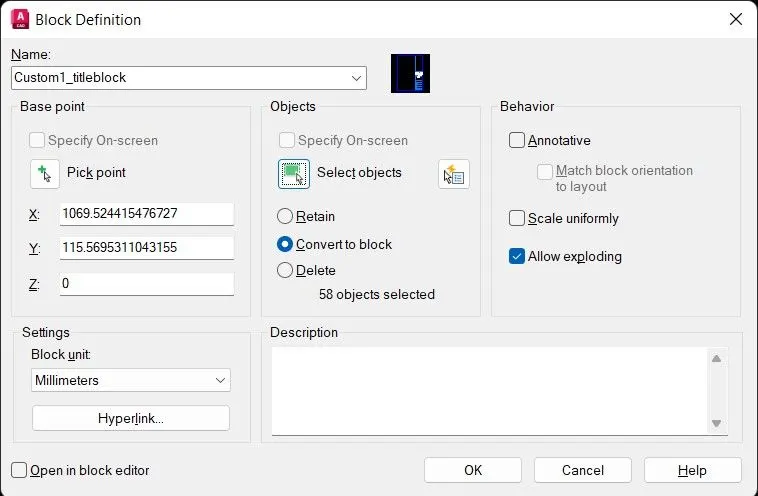
- Enter command "B" to convert it into a block.
- By entering the data the drawing will turn into block.
For Custom2_titleblock:
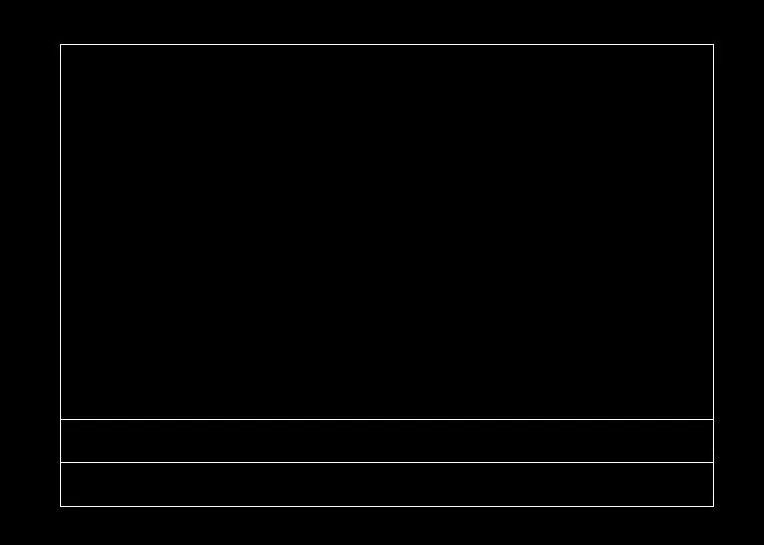
- For the second bolck draw a rectangle of the size (210 X 297 mm) as it is the standard size of the A4 size paper.
- Now explode the rectangle so that we can work on each line separetly.
- Now give offset from bottom to top to create a title box.
- Now give offset to the vertical lines to create boxes of the desired size.
- Now trim the excess lines and then the format of the title block is ready.
- Now as the sheet format is ready use the "DTEXT" of the desired/Preffered size to notate the boxes for what they are going to used for.
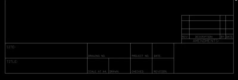
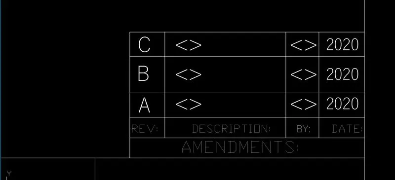
- Now entering all the data given in the drawing.
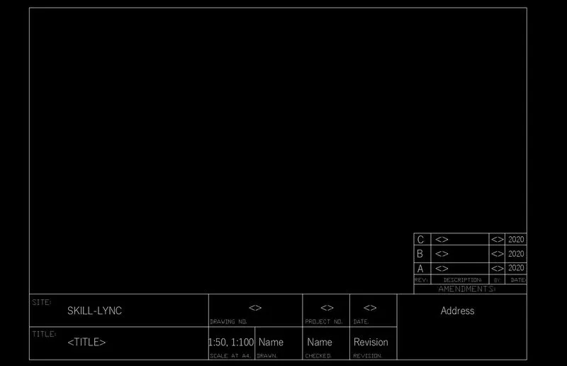
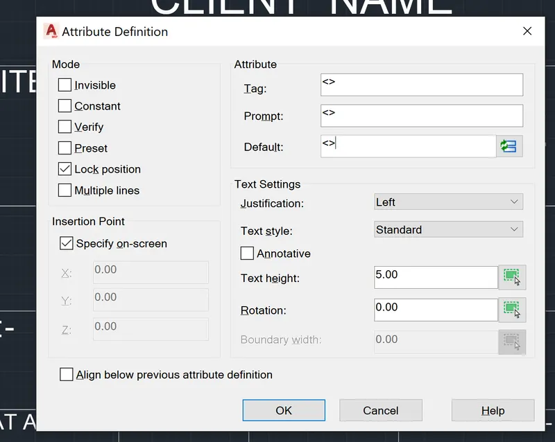
- Now use the command "ATT" to give the attribute definition to the following boxes.
- The dialogue box for the attribute definition looks as below.
- Do the same thing for all the boxes so that a proper format for the sheet is prepared.
- After entering all the attribute definition select the whole drawing and then enter command "B" to convert it into a block.
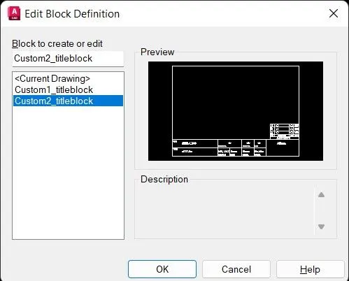
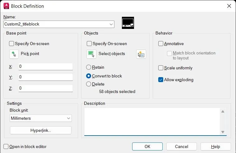
- By entering the data the drawing will turn into block.
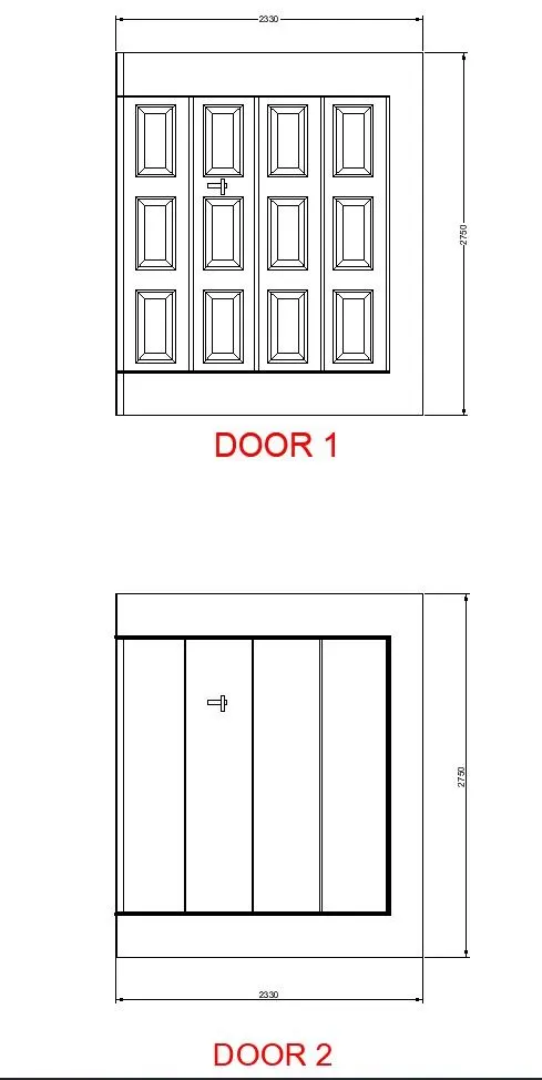
2. Create the doors type for warehouse as shown in the Figure. You need to create each door type as per standard size or given dimensions. Create the blocks of this door type after creating them.
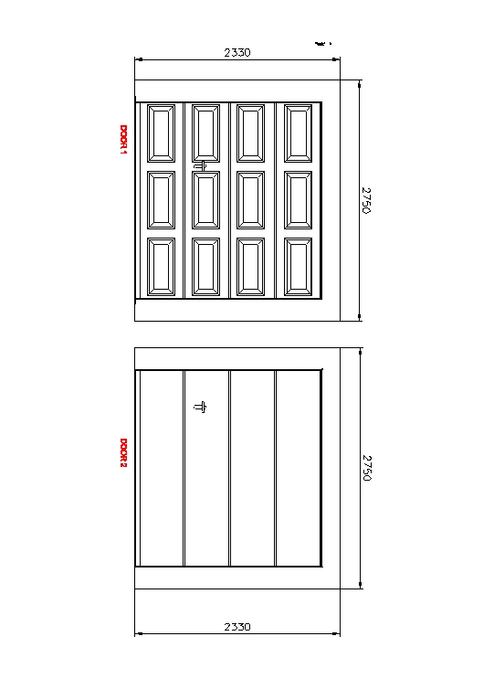
2.Ans:-
AIM:- To creating the door types for warehouse as per given drawing by using AutoCad tools.
Procedure:
For Warehouse_doortype1:
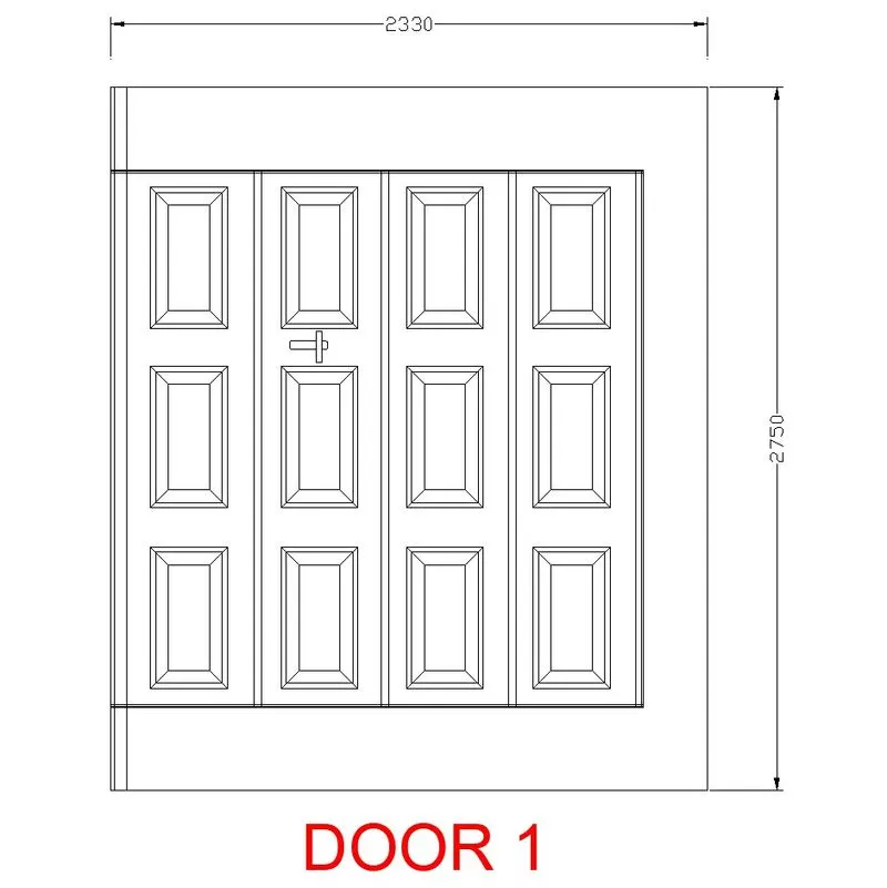
- In command enter rec and select dimension and give length as 2330 and width as 2750 and press enter
- In command enter Explode and select the above created rectangle
- In command enter O and select the left vertical line and give offset distance as 100 and create an offset lines by moving the cursor towards right.
- Enter o and select the above created line and give offset distance as 557.5 and created 3 offset lines.
- Enter o and select the top horizontal line and give offset distance as 916.6 and create 2 offset lines by moving the cursor towards down.
- Enter Tr and trim the horizontal lines between left vertical outer line and second vertical line
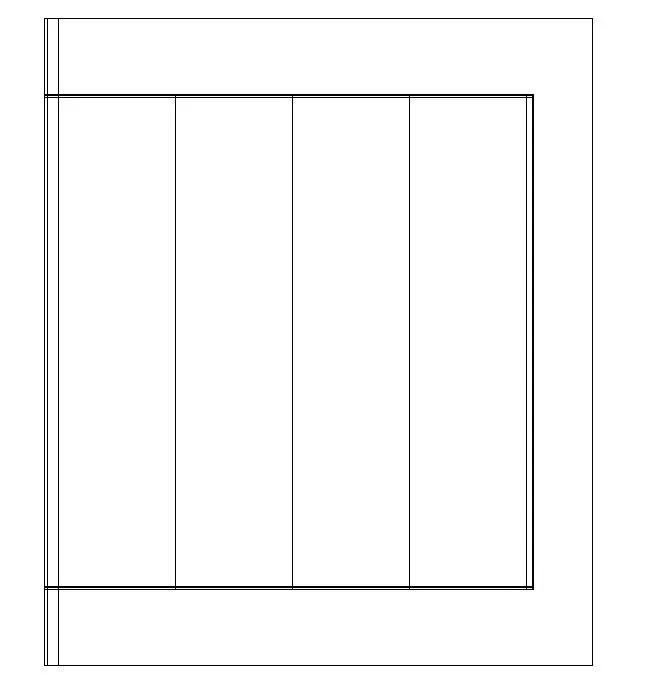
- Enter rec and click the point inside the top right rectangle segment and create a rectangle inside it by having approximate space outside.
- Enter o and give offset distance as 30 and select the above created rectangle and offset inside it
- Enter o and give offset distance as 50 and select the above created rectangle and offset inside it
- Select line com
- mand and join the corners on four sides of the rectangle which was just created
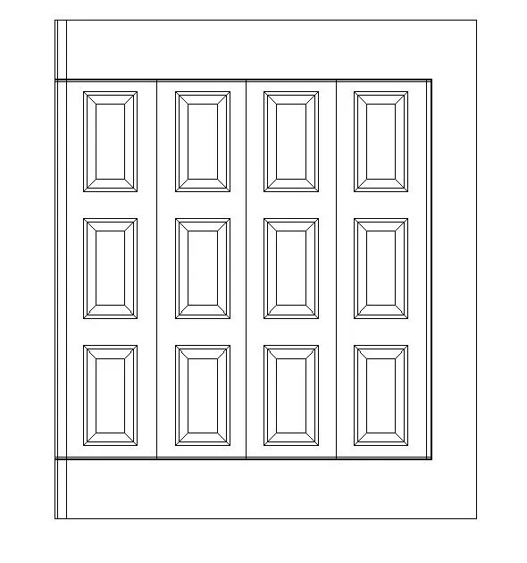
- Enter co and select the above created rectangle and specify the base point and copy it to the other rectangle segments as shown below
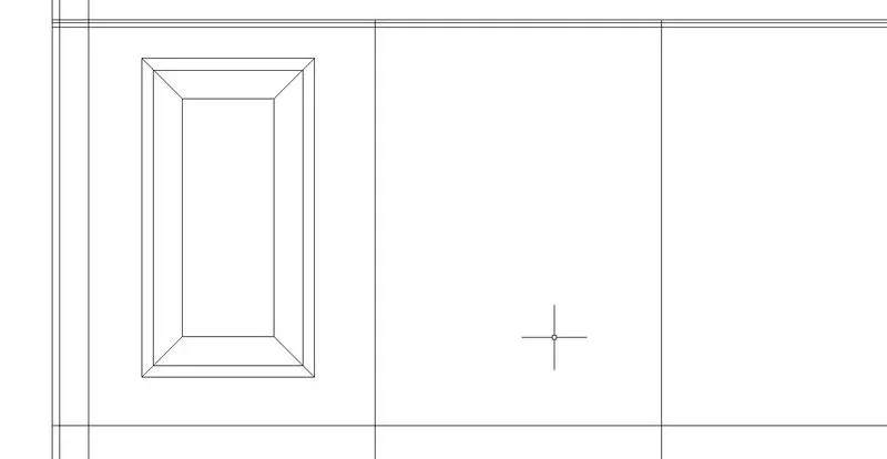
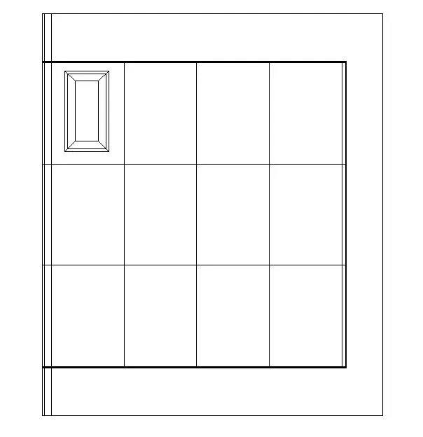
- Using rec and fillet command create the handle and enter tr and trim the excess lines
- Enter the REC for door handle to draw it.
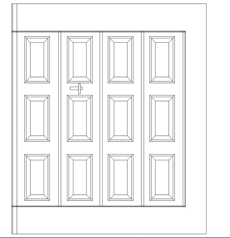
- Select linear dimension in the ribbon and give dimension by clicking the both end points as shown below
- Enter B, which opens the block definition dialog box
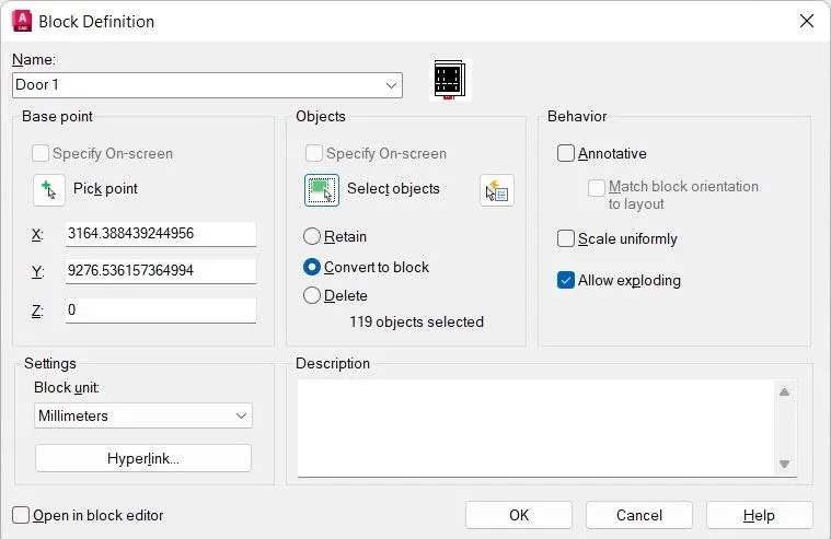
- Give name as Door1 and specify the insertion point and select the template as an object and block unit in millimeter and click ok to create this template as a block.
- Result:
- The following result is obtained by the above steps
For Warehouse_doortype2:
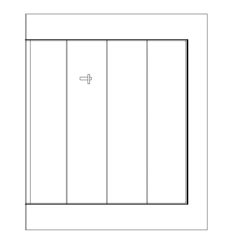
- Enter co and select the above created vertical and horizontal lines and the handle
- Select the base point and copy it nearby as shown below
- Enter B, which opens the block definition dialog box
- Give name as Door2 and specify the insertion point and select the template as an object and block unit in millimeter and click ok to create this template as a block.
- Result:
- The following result is obtained by the above steps
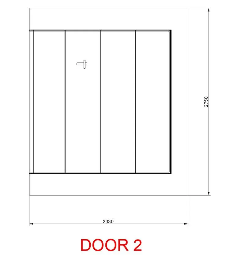
Final result: Door types are drawn as per drawing showwn below
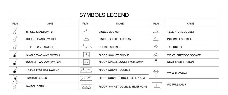
3. Create each symbol as a block with the name given in the legend. After creating the blocks arrange them in the legend as shown in the Figure.
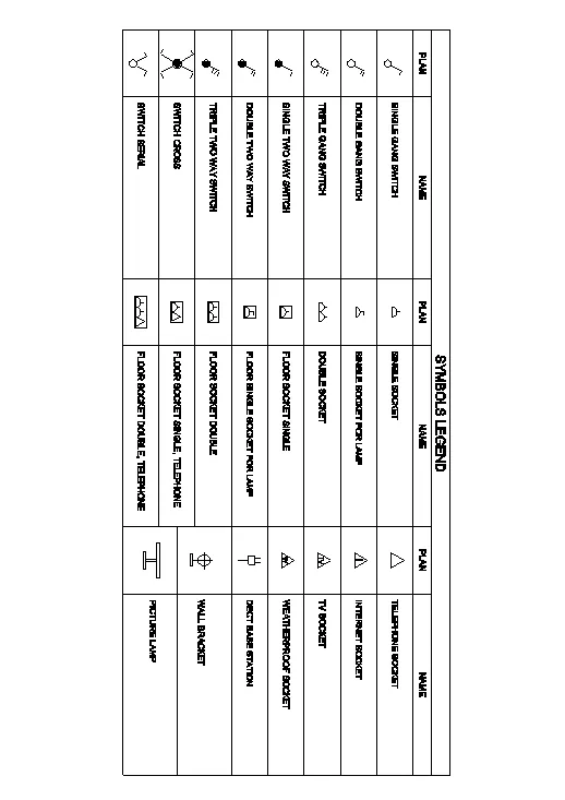
3.Ans:-
AIM:-
- To create the following legend and convert them into blocks in AutoCAD.
Introduction:
The following commands and tools are used for this drawing.
- Line: It helps to create a line between two points
- Rectangle: It helps to create a four-sided geometry with a desired length and width.
- Offset: It helps to offset an object at a particular distance.
- Move: It helps to move an already existing object from one point to the other by picking a base point.
- Copy: It helps to copy an already existing object from one point to the other by picking a base point.
- Trim: It helps to trim off the extra lines or objects of a selected object which is created while using other tools.
- Erase: It helps to erase a selected object.
- Break at point: It helps to break a line by clicking on a selected point.
- Fillet: It helps to fillet the corner of the object by selecting the two-corner line and giving radius.
- DT: Single line text helps to create single line of text
- MT: Multiline text helps to create a set of lines or paragraph
- BLOCK: It helps to create a set of different components in to single object
- BLOCK EDITOR: It helps to edit the blocks with parameter and action.
- Explode: It helps to explodes an object in to each segment.
- Field: It helps to display the property and format of an object on workspace after creating it into block.
- Hatch: It helps to differentiate an object with the pattern
Note:
- Keep Ortho on and Object snap on which are in the status bar throughout the drawing which helps to find midpoint, center point and so on.
Procedure:
- Enter zoom and enter all in the command.
- In command enter rec and select dimension and give length as 20700 and width as 7800 and press enter
- In command enter Explode and select the above created rectangle
- In command enter O and select the left vertical line and give offset distance as 30 and create an offset lines by moving the cursor towards right.
- Enter o and give offset distance as 1500
- Enter o and give offset distance as 5400
- Enter o and give offset distance as 1500
- Enter o and give offset distance as 5400
- Enter o and give offset distance as 1500
- Enter o and give offset distance as 5400
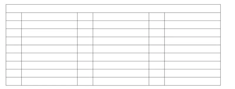
- Enter DTEXT commond and enter the given data in the table
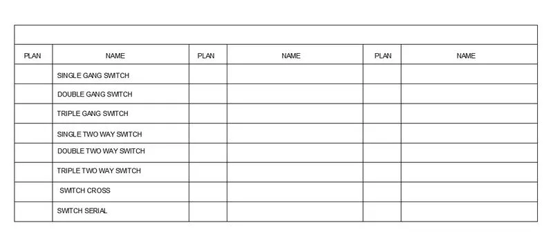
- Enter circle commond and drawn appropirate radius and line commond to complete the symbols
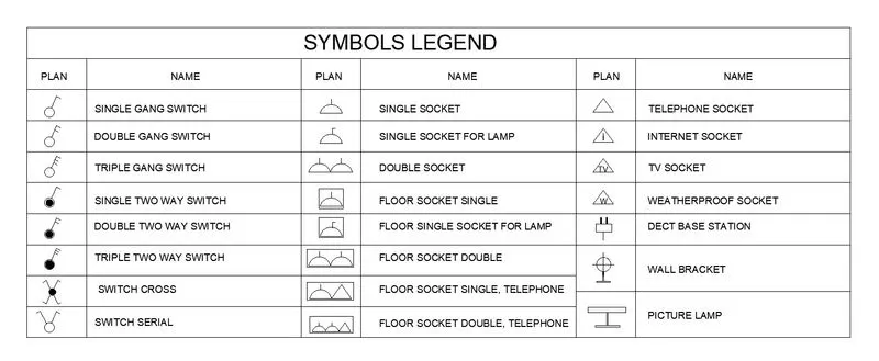
- Similarly all the symbols are dawn asper drawing
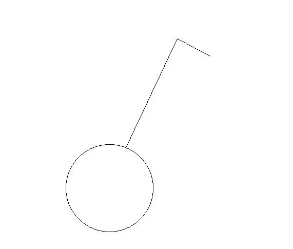
- After creating the symbols arrange in proper position.
- Enter block commond and select the symbol along with text and block it as their given name
- All symbols are blocks with their names
- Block symbols and names are shown below
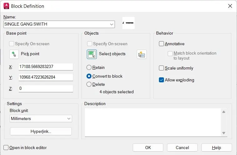
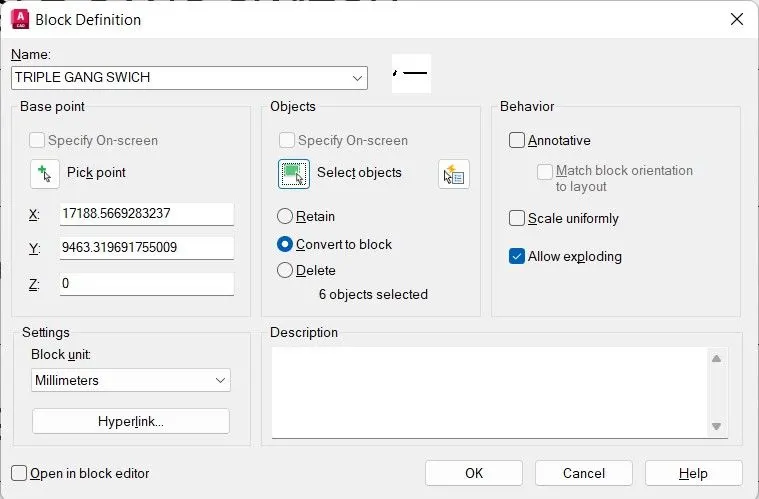
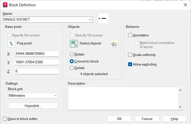
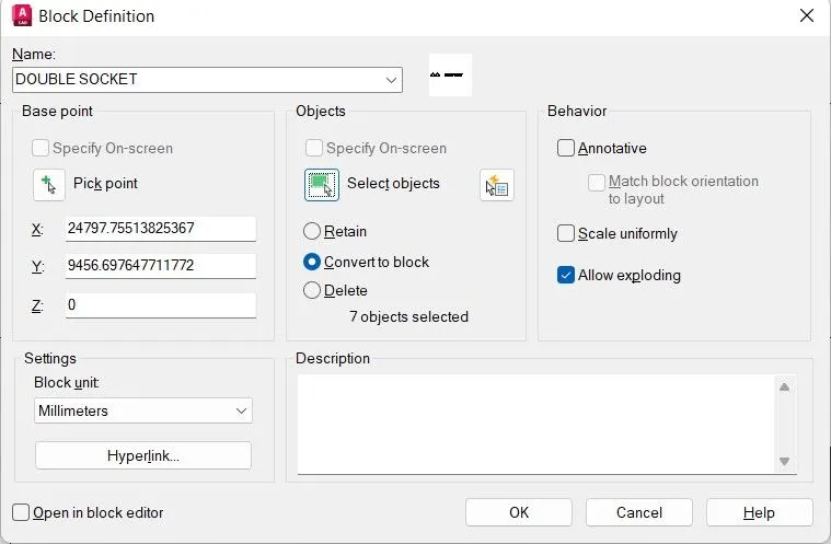
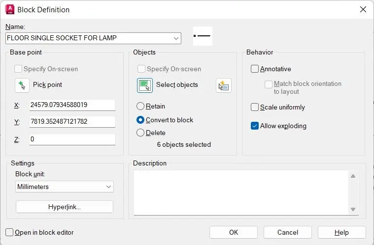
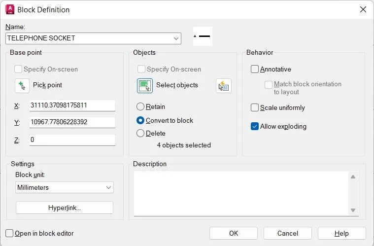
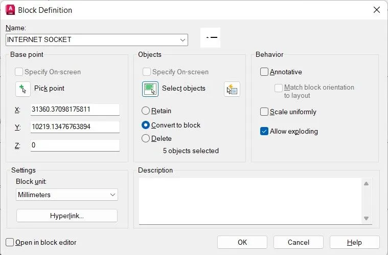
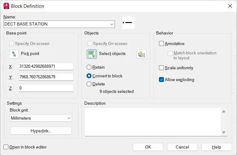
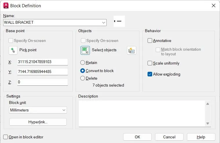
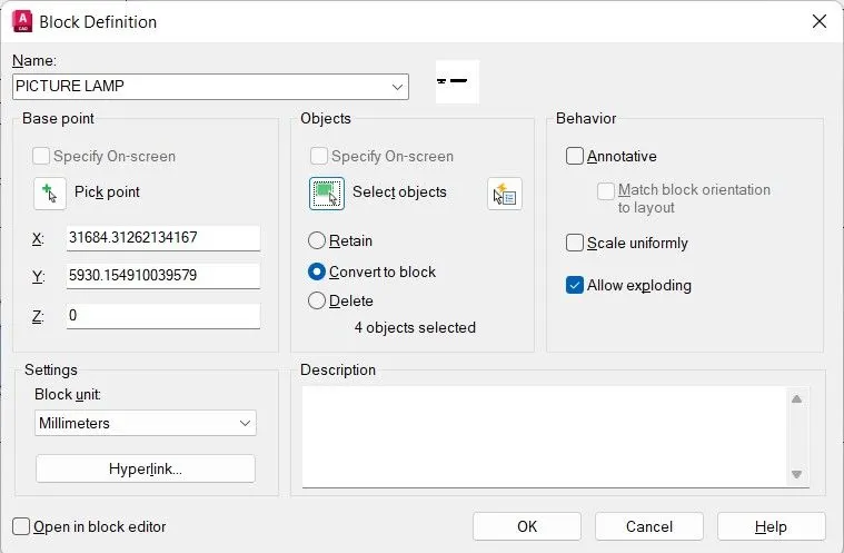
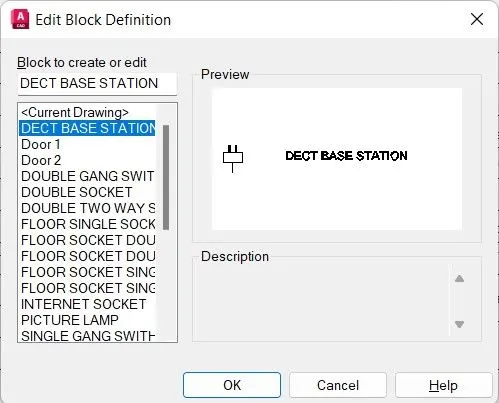
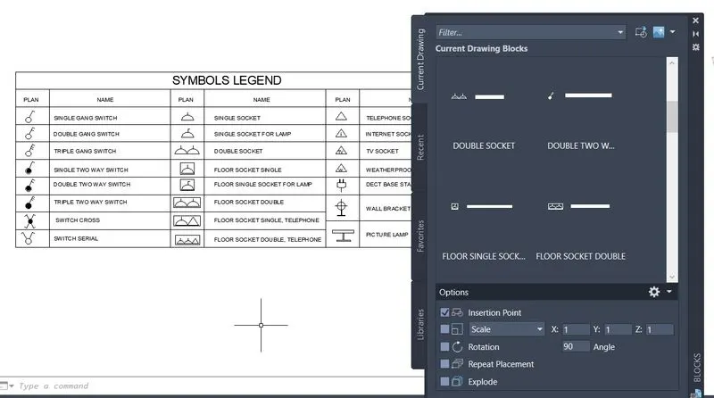
- After block it with their names each symbol act as a block shown below
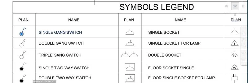
- Result:
- The following result is obtained by the above steps
4. Create the door type for residential building as a block. Save the name of the blocks as type. Use given dimensions or assume dimensions as per industry standards.
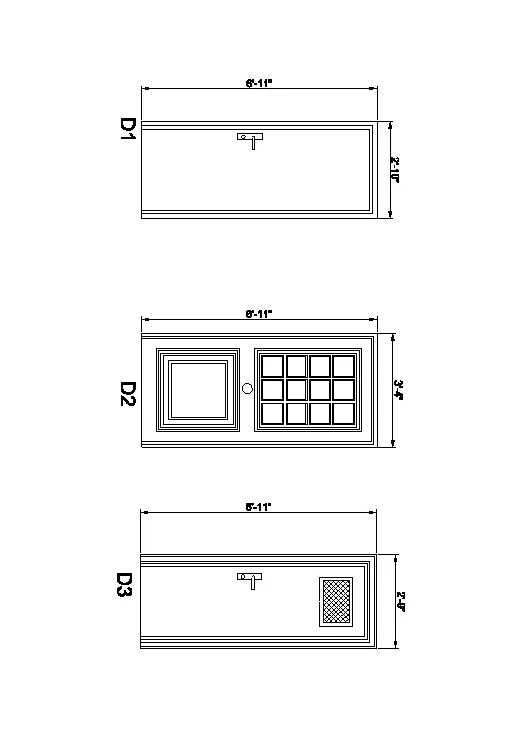
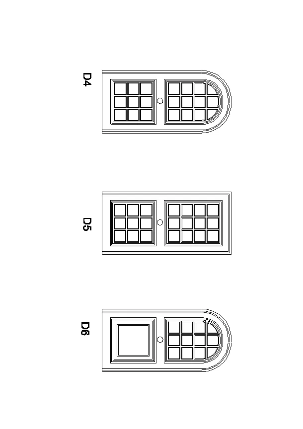
4.Ans:
AIM:- To create the following door types for residential building and convert them into blocks in AutoCAD.
Procedure:
For D1:
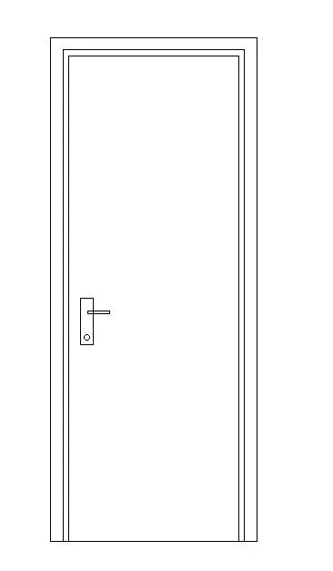
- In command enter rec and select dimension and give length as 2’10” and width as 6’11” and press enter
- Enter o and select the above created rectangle and give offset distance as 3” and move the cursor inside the rectangle.
- Enter o and select the above created rectangle and give offset distance as 2” and move the cursor inside the rectangle.
- Enter trim and select the object as a whole and trim the inner bottom horizontal lines
- Enter extend and select the object as a whole and extend the vertical lines as shown below
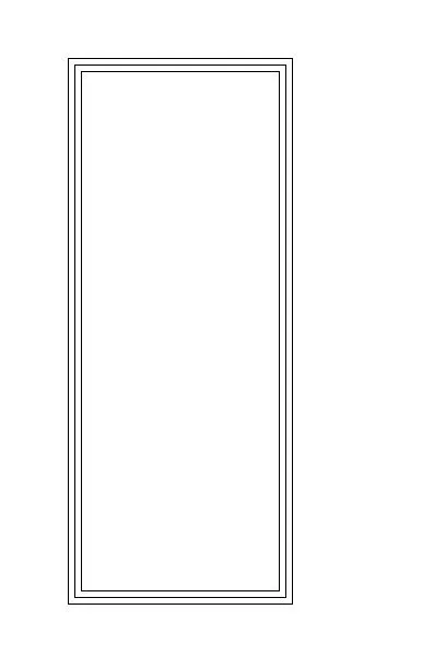
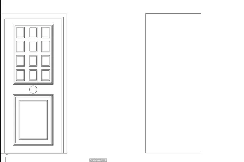
- Using rectangle and circle command create a handle with random dimension. Create 2 rectangle perpendicularly like handle with a circle for key hole and place is left side below geometric center of the door.
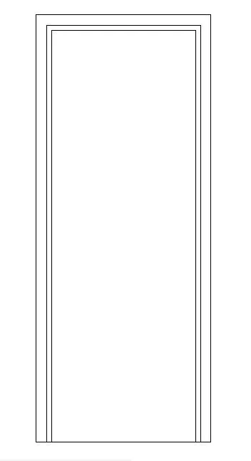
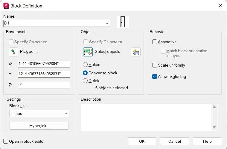
Enter B, which opens the block definition dialog box
- Give name as D1 and specify the insertion point and select the template as an object and block unit in inches and click ok to create this door as a block.
- Result for D1:
- The following result is obtained by the above steps
For D2:
- In command enter rec and select dimension and give length as 3’4” and width as 6’11” and press enter
- Enter o and select the above created rectangle and give offset distance as 2” and move the cursor inside the rectangle.
- Enter o and select the above created rectangle and give offset distance as 1” and move the cursor inside the rectangle.
- Enter trim and select the object as a whole and trim the inner bottom horizontal lines
- Enter extend and select the object as a whole and extend the vertical lines.
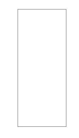
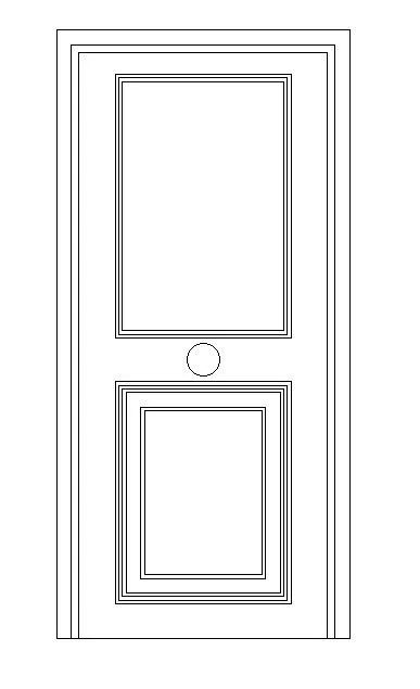
- Enter rec and create rectangle of length 5” and width 4.75” outside the door
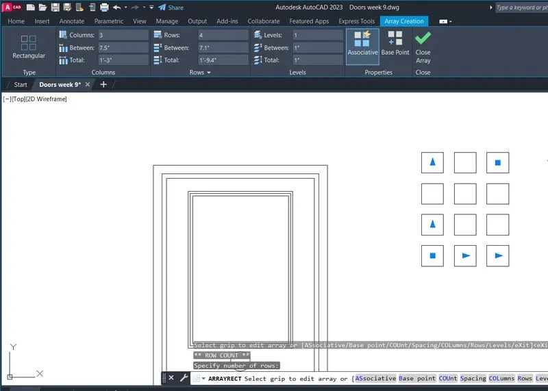
- Select array command and give the settings and form an array of rectangle as shown below.
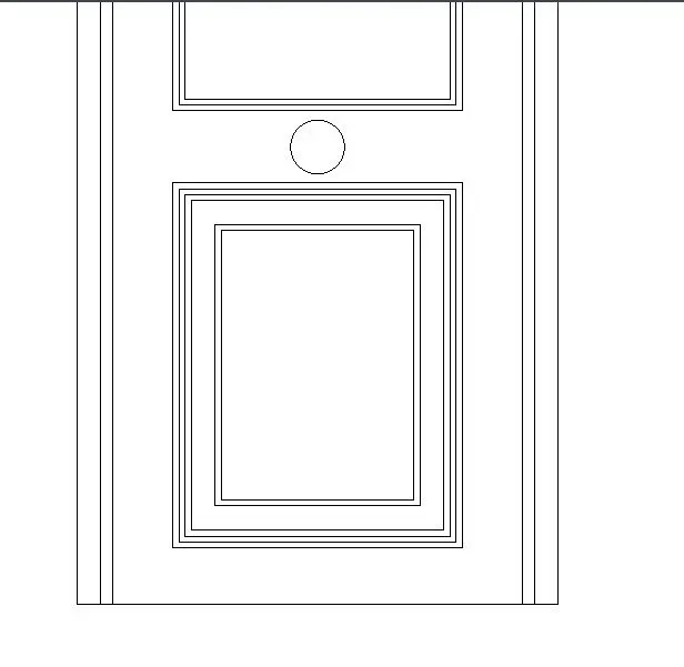
- Enter L and create outer temporary line of array
- Enter O and give offset distance as 1” and move the cursor outside and create 3 offset lines as shown below
- Select the temporary lines around array and press delete
- Enter o and give offset distance as 0.5” and select the small rectangle which create earlier for array and move the cursor inside the rectangle.
- Repeat for all smaller rectangles
- Enter rec and with the help of snapping reference line pick the corner random point little away from the above rectangle and form a rectangle in random dimension with some distance away from the bottom of the door
- Enter o and select the above created rectangle and give offset distance as 1” and create 3 offset rectangles by moving the cursor inside.
- With the same procedure create 2 offset rectangles of distance 3” and 1” one by one.
- Enter c and create a small circle between top and bottom rectangle
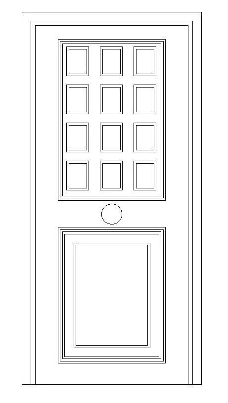
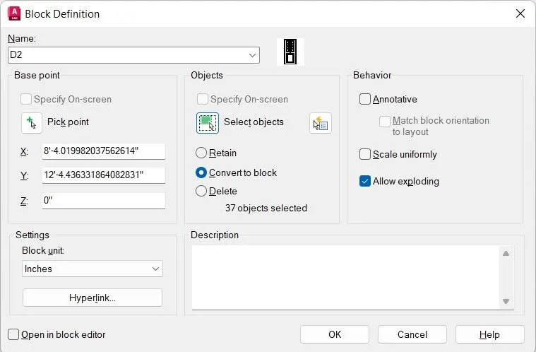
- Enter B, which opens the block definition dialog box
- Give name as D2 and specify the insertion point and select the template as an object and block unit in inches and click ok to create this door as a block.
- Result for D2:
- The following result is obtained by the above steps
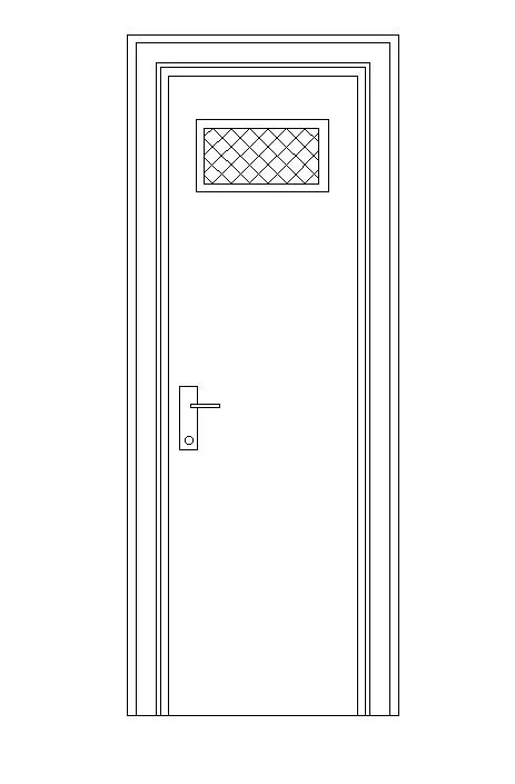
For D3:
- In command enter rec and select dimension and give length as 2’9” and width as 6’11” and press enter
- Enter o and select the above created rectangle and give offset distance as 1” and move the cursor inside the rectangle.
- Enter o and select the above created rectangle and give offset distance as 2” ,1”, 1” respectively and move the cursor inside the rectangle like the above procedure.
- Enter trim and select the object as a whole and trim the inner bottom horizontal lines
- Enter extend and select the object as a whole and extend the vertical lines
- Enter co and copy the handle created for D1 and place it geometric center
- Select the rectangle command and pick the a random point on top and create a rectangle without touching the side
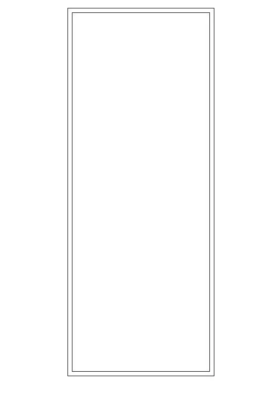
- Enter o and select the above created rectangle and give offset distance as 1” and move the cursor inside the rectangle.
- Enter h and select the following settings
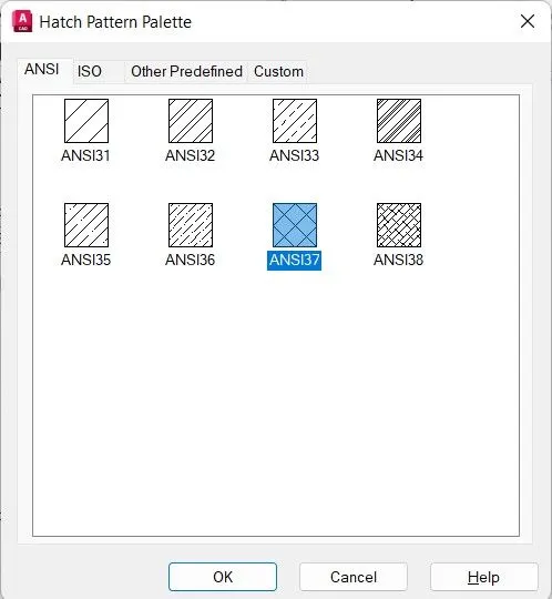
- Pick a point inside the above created rectangle and form hatch
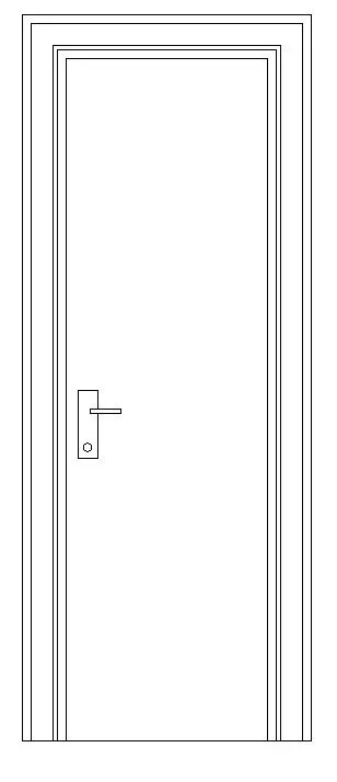
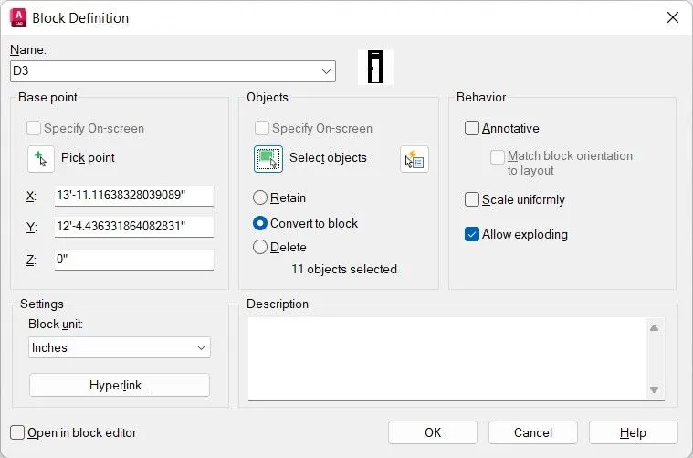
- Enter B, which opens the block definition dialog box
- Give name as D3 and specify the insertion point and select the template as an object and block unit in inches and click ok to create this door as a block.
- Result for D3:
- The following result is obtained by the above steps
- For D5:
- Enter co and select the Frame and top rectangular array of D2 and pick a base point and place it.
- Enter explode and select the array
- Enter co and select the single rectangle from the array and copy it outside the frame.
- Select the outer frame rectangle of the above rectangle inside the door frame and place it below
- Select array command and give settings as follow
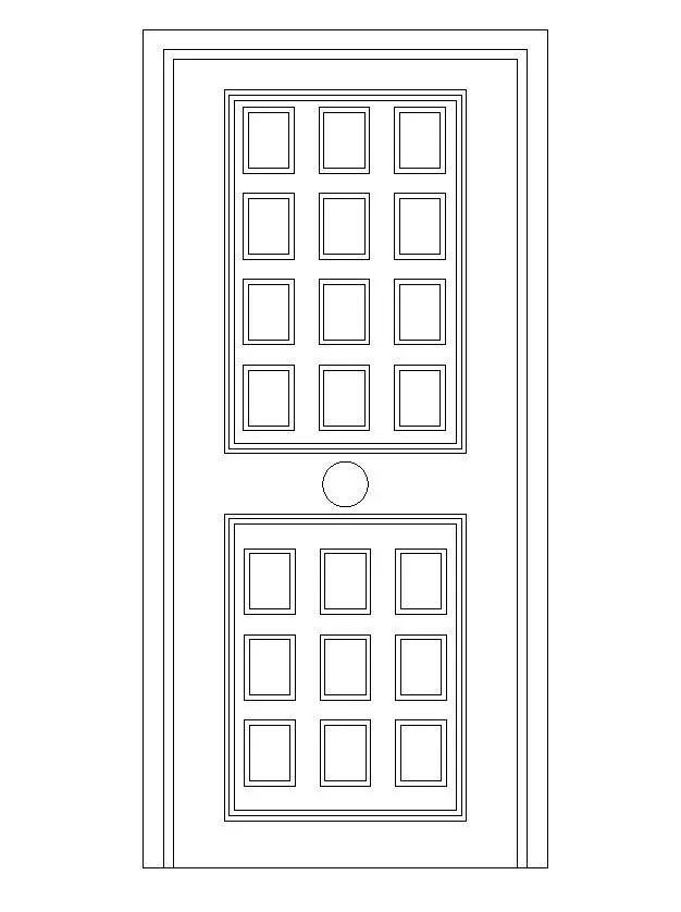
- Select offset command and select the bottom rectangle and give offset distance as 1” and create 2 offset rectangles by moving the cursor inside.
- Enter co and select the array which created earlier and place it inside the offset rectangles
- Enter explode and select the offset rectangles
- Select the bottom lines of offset rectangle and delete
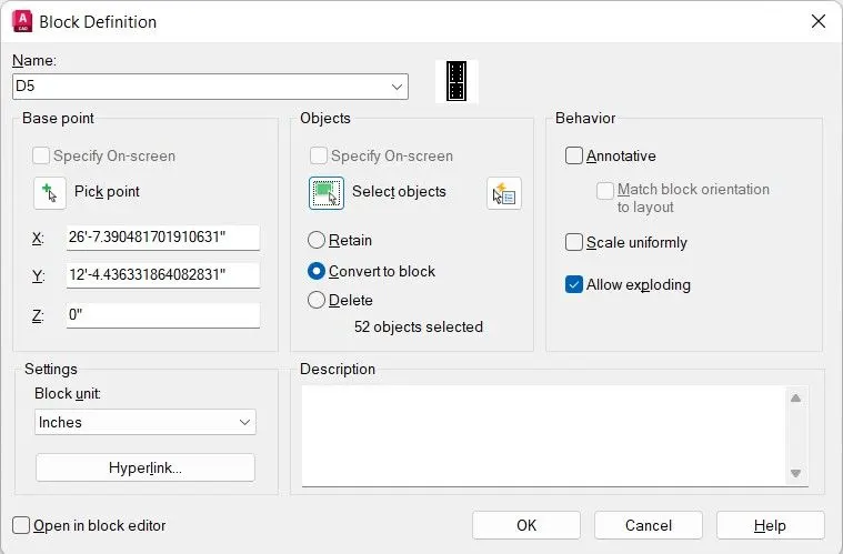
- Enter B, which opens the block definition dialog box
- Give name as D5 and specify the insertion point and select the template as an object and block unit in inches and click ok to create this door as a block.
- Result for D5:
- The following result is obtained by the above steps
- For D4:
- Enter co and select the door D5 and pick the base point and place it nearby.
- Enter line commond draw the horizontal line at curve point
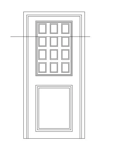
- Trim the boundaries and enter circle command select 2P circle
- Specify first and second point
- similarly offset point also drawn
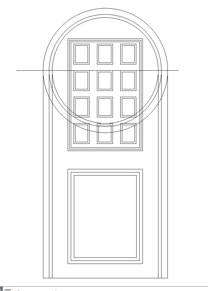
- Select trim command and trim all the unwanted lines
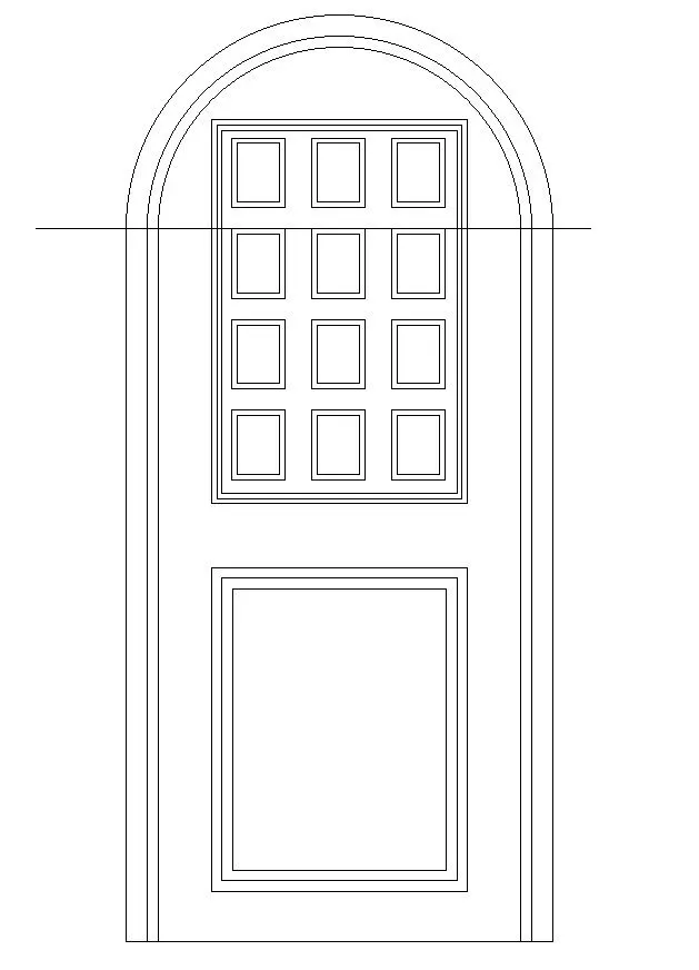
- Same procedure will be follows for internal offset points
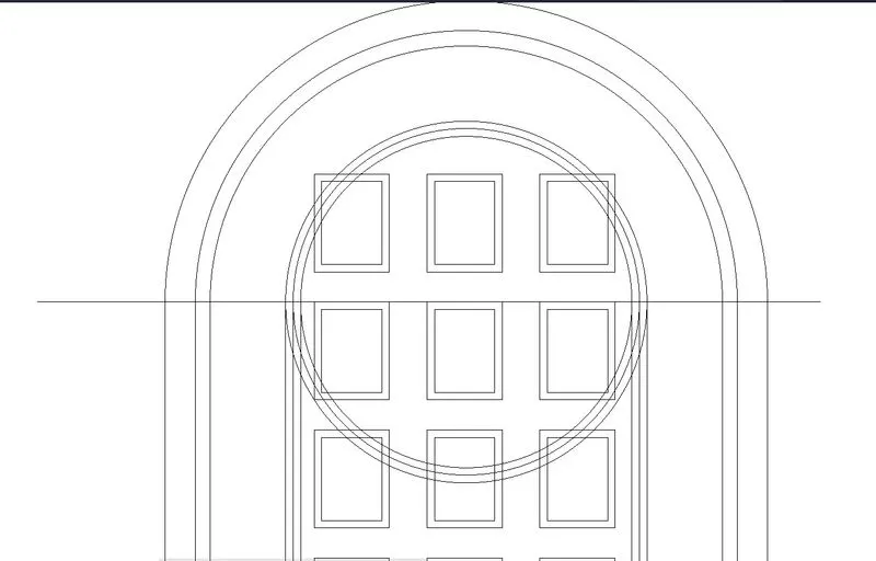
- Trim all the unwanted lines.
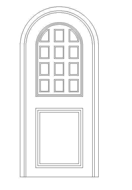
Enter B, which opens the block definition dialog box
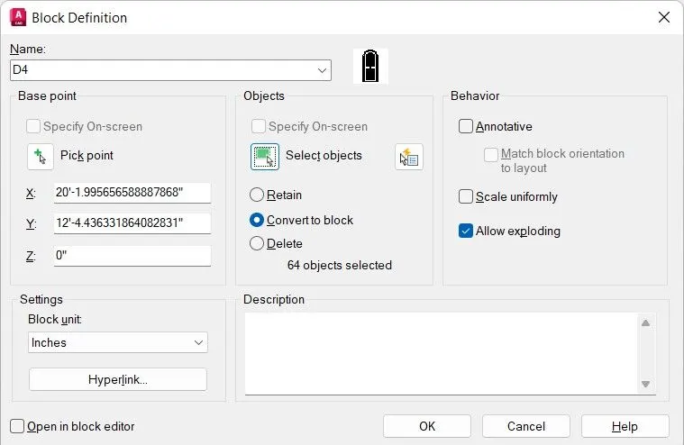
- Give name as D4 and specify the insertion point and select the template as an object and block unit in millimeter and click ok to create this door as a block.
- Result for D4:
- The following result is obtained by the above steps
- For D6:
- Enter co and select the door D4 and pick the base point and place it nearby.
- Select the bottom rectangular array and press delete as shown below
- Enter O and give offset distance as 2” and select the bottom inner rectangle and move the cursor inside.
- Enter O and give offset distance as 1” and select the bottom inner rectangle and move the cursor inside to form door type D6 as shown below.
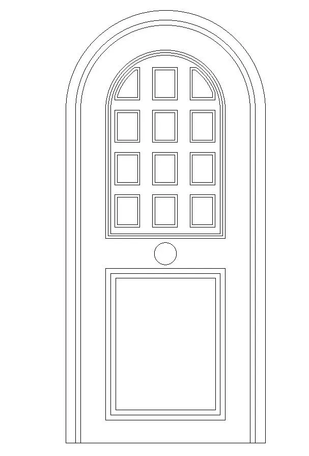
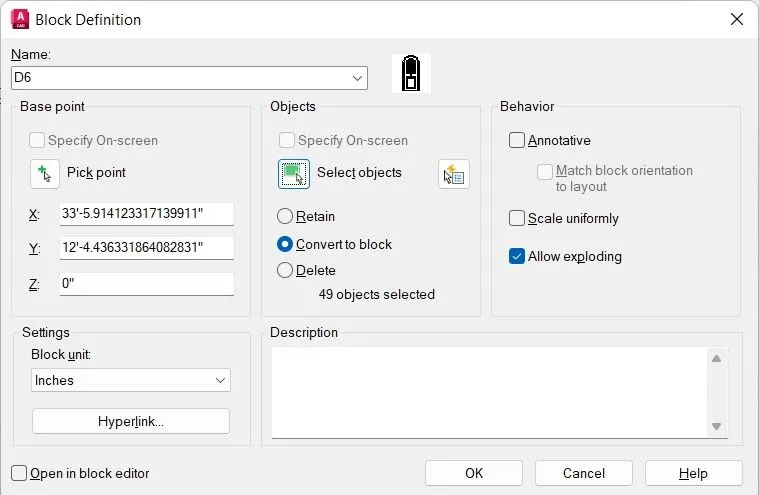
- Enter B, which opens the block definition dialog box
- Give name as D6 and specify the insertion point and select the template as an object and block unit in inches and click ok to create this door as a block.
- Result for D6:
- The following result is obtained by the above steps
5. Create each shape as a block as shown in the Figure. Save the block and insert them on the table as shown in the Figure.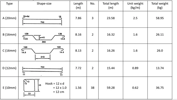
5.Ans:-
AIM:-
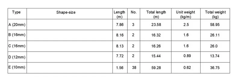
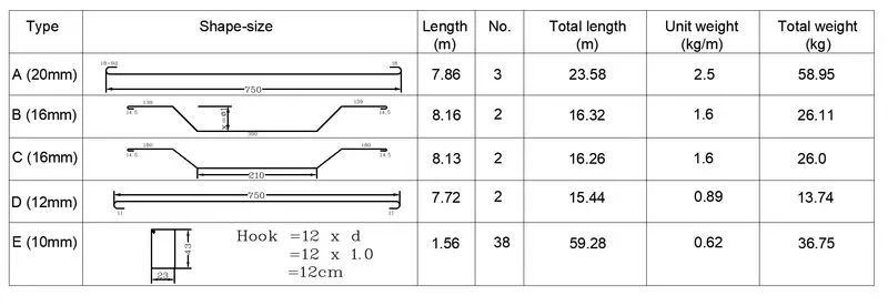
- To create the following BBS table by inserting the blocks in AutoCAD.
Procedure:
- In command enter rec and select dimension and give length as 26506 and width as 9704 and press enter
- In command enter Explode and select the above created rectangle
- In command enter O and select the left vertical line and give offset distance as 2255 and create an offset lines by moving the cursor towards right.
- Enter o and give offset distance as 10121 and select the above created line and create an offset line
- Enter o and give offset distance as 1904 and select the above created line and create an offset line
- Enter o and give offset distance as 1496 and select the above created line and create an offset line
- Enter o and give offset distance as 3758 and select the above created line and create an offset line
- Enter o and give offset distance as 3458 and select the above created line and create an offset line
- Enter o and give offset distance as 3515 and select the above created line and create an offset line
- Enter o and give offset distance as 1300 for horizontal lines
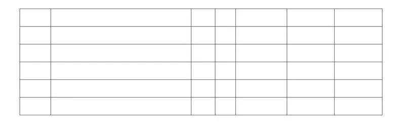
- Enter DTEXT command and write the given data.
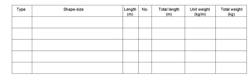
- Enter all the data given in table
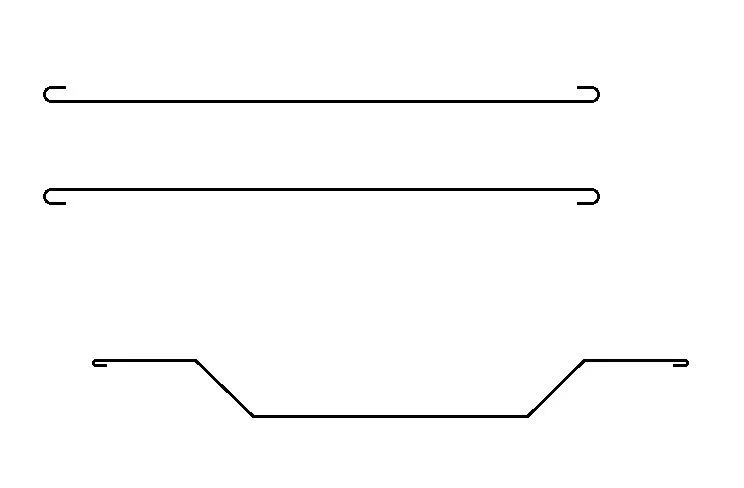
- Enter line command and draw the reinforcement shape
- Specify the hook length as 18xdia
- The other shape of reinforcement will be drawn as per dimensions

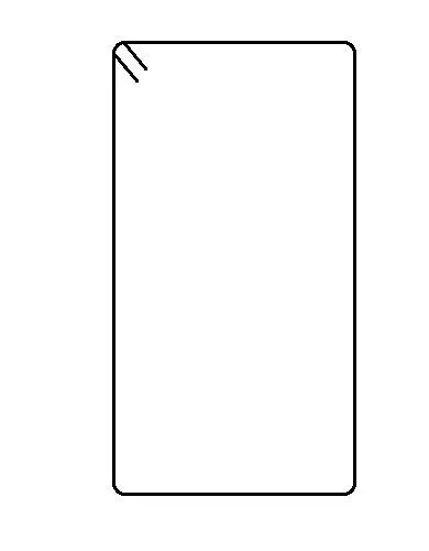
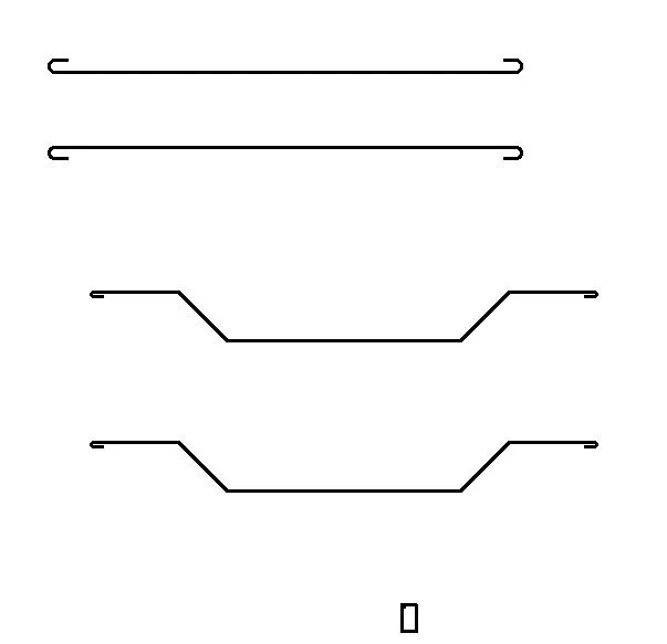
- Enter move command and place the all shape of reinforcement in their position
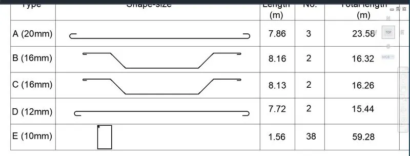
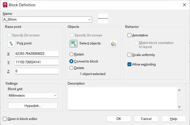
- Enter block command and select the shape of the object and given name as A_20mm
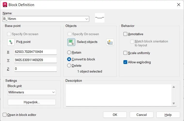
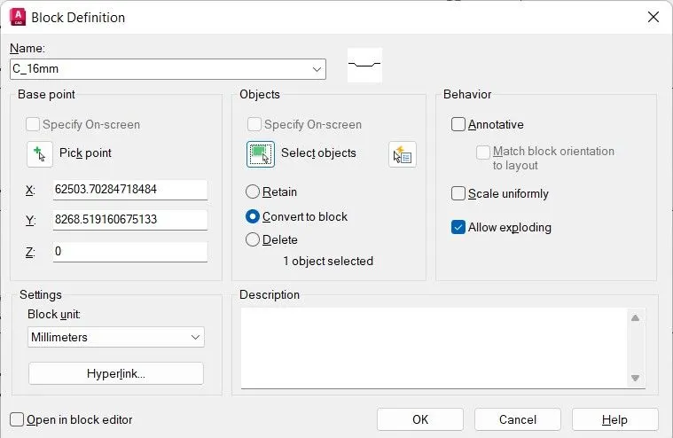
- Similarly all other shapes will be blocked with their names shown below
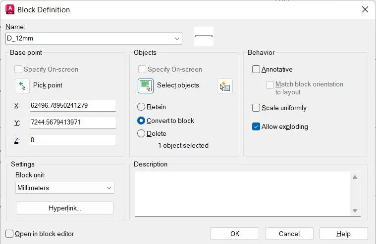
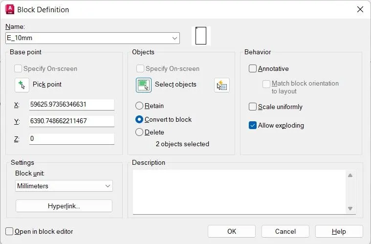
Result:- BBS is created as per given data and blocked with their names
Thank you