Creating a Floor plan, Footing detail and Isometric view using AutoCad
ANSWERS FOR WEEK-2 CHALLENGES
C-1: Cross Section of load bearing wall over spread footing
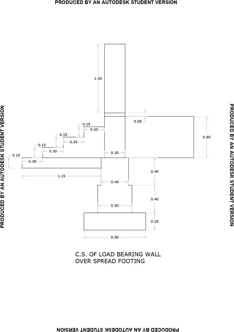
Aim: To draw the cross section of wall over footing as given
Procedure:
Step:1
- Create a rectangle by using Rec in command box
- Specify the first point
- Click on dimension in command box
- Then specify length and width as 0.9,0.25
Step:2
- Create a rectangle by using Rec in command box
- Specify the first point at 0.2 units from top of first rectangle
- Click on dimension in command box
- Then specify length and width as 0.5,0.4
Step:3
- Create a rectangle by using Rec in command box
- Specify the first point at 0.05 units from top of second rectangle
- Click on dimension in command box
- Then specify length and width as 0.4,0.4
Step:4
- Create a rectangle by using Rec in command box
- Specify the first point at 0.05 units from top of third rectangle
- Click on dimension in command box
- Then specify length and width as 0.3,0.6
Step:5
- Create a rectangle by using Rec in command box
- Specify the first point at top of fourth rectangle
- Click on dimension in command box
- Then specify length and width as 0.3,1.05
- Then create line above 0.05 units from bottom of rectangle
Step 6
- Create a rectangle by using Rec in command box
- Specify the first point at right top point of fourth rectangle
- Click on dimension in command box
- Then specify length and width as 1,0.6
Step 7
- Create a line by using L in command box
- Specify the first point at top of third rectangle
- Use dimension in command box
- Then move the cursor left side and give length as 1.15
- Then use offset command and mention 0.15
- Click on line and move cursor down ward and click enter
- Then press esc
- And join the 2 lines by using line command
Step 8
- Create a poly line by using PL in command box
- Specify the first point at 0.3 units from line
- Use dimension in command box
- By moving cursor up wards give length as 0.15 and move cursor right side give length 0.3 and continue the same procedure 3 times
- Then press esc
Step 9
- Give the all dimensions using "DIM" in command box
- By using "Text" commant the drawing given to the titles
Result: The given drawing is successfully drawn by given dimensions which is shown below
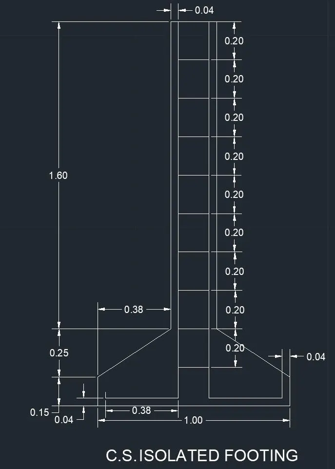
2.Cross section of a isolated footing
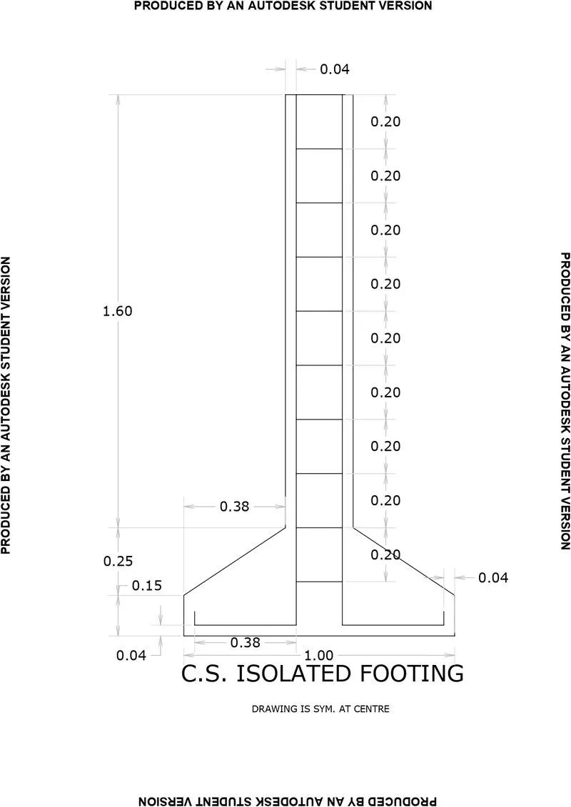
Aim: To draw the C/S of isolated footing as given
Procedure:
Step 1 :
- Create poly line by using PL in command box
- Specify the first point by 0,0 in command box
- Specify the next point @0,0.15
- Specify the next point @0.38,0.25
- Specify the next point @ 0,1.60
- Specify the next point @0.24,0
- Specify the next point @0, -1.60
- Specify the next point @ 0.38, -0.25
- Specify the next point @ 0, -0.15
- Press C to complete the line
Step 2:
- Draw line at a distance of 0.04 units from the top command"
- With dynamic input on give value 0.04, then give the length of 1st line as 1.96
- Next give the coordinate @0, -0.38
- Draw the third line by giving the coordinates @0,0.06
Step 3:
- Copy the first line by command "co" click displacement and give value of 0.16 units.
- Copy the second line horizontal by "co" click on the base point and dragging to desired position.
- Copy the third line by giving command "co" and selecting the base point of the object.
Step:4
- Give offset from the top line with an offset distance of 0.2 units.
- Give the command "o" an select the object give the offset distance as 0.2, select multiple option a 9 such lines
- Trim the excess lines using trim command
Step 5
- Give the all dimensions using "DIM" in command box
- By using "Text" commant the drawing given to the titles
Result: The given drawing is successfully drawn by given dimensions which is shown below
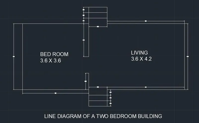
- Line diagram of a two Bedroom building
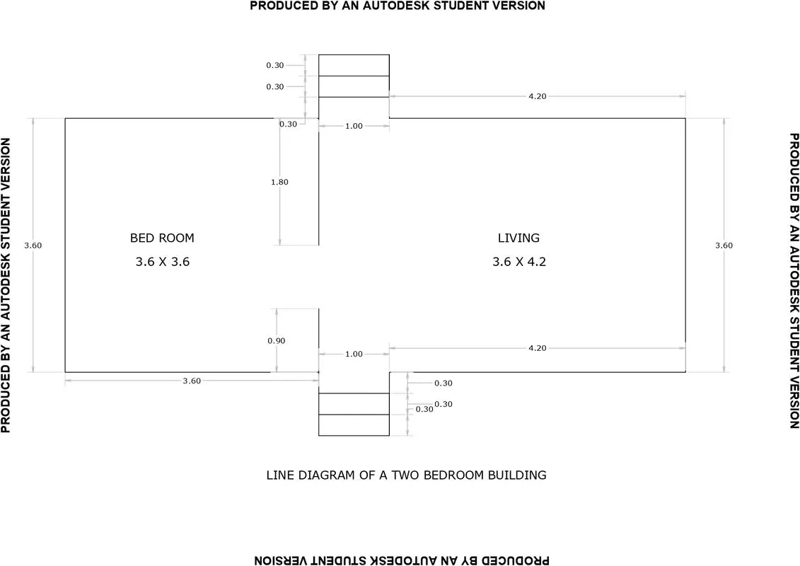
Aim: To draw the line diagram of a two-bedroom building as given in the figure
Procedure:
Step 1
- Select line tool by typing “L” in command box
- Locate starting point by using cursor or typing a coordinate {I am taking 0,0 as my start point}
- Specify the next point @0,3.6
- Specify the next point @3.6,0
- Specify the next point @0,0.9
- Specify the next point @1,0
- Specify the next point @0,-0.9
- Specify the next point @4.2,0
- Specify the next point @0,-3.6
- Specify the next point @-4.2,0
- Specify the next point @0,-0.9
- Specify the next point @-1,0
- Specify the next point @0.9,0
- Then type “c” to close the line
Step 2
- Select line command
- By using the cursor give starting point of line as per given figure
- Then select dimension in command box
- By moving cursor downwards give a length of 1.8
Step 3
- Select line command
- By using the cursor give starting point of line as per given figure
- Then select dimension in command box
- By moving cursor upwards give a length of 0.9
Step 4
- Select offset command and give offset length of 0.3
- At step area select the line and move the cursor downwards and press enter and repeat it for 2 times
- Repeat the same procedure for second steps area also
Step 5
- Give the all dimensions using "DIM" in command box
- By using "Text" commant the drawing given to the titles
Result: The given drawing is successfully drawn by given dimensions which is shown below
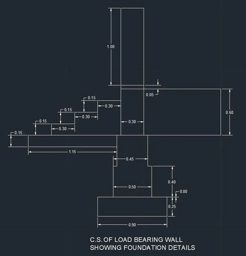
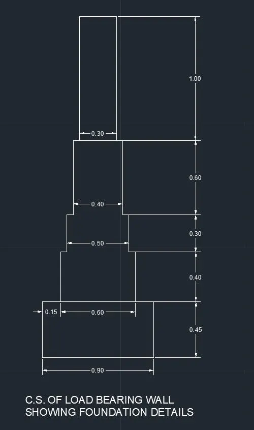
- Cross Section of load bearing wall showing foundation details:
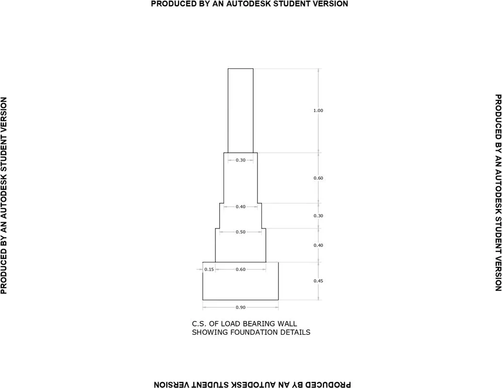
Aim: To draw the Cross section of a Load bearing wall showing the foundation details as shown in the figure
Procedure:
Step 1
- Create a rectangle by using “rec” in command box
- Specify the first point
- Choose dimension in command box
- Specify length as 0.9 and width as 0.45
Step 2
- Create a rectangle by using "rec" in common box
- Specify the centre point of the previous rectangle top by tracking the centre
- Choose dimension in command box
- Specifify length as 0.6 and width 0.4
Step 3
- Create a rectangle by using "rec" in common box
- Specify the centre point of the previous rectangle top by tracking the centre
- Choose dimension in command box
- Specifify length as 0.5 and width 0.3
- Now trim the internal lines by using "TR" in command box
Step 4
- Create a rectangle by using "rec" in common box
- Specify the centre point of the previous rectangle top by tracking the centre
- Choose dimension in command box
- Specifify length as 0.3 and width 1 unit
Step 5
- Give the all dimensions using "DIM" in command box
- By using "Text" commant the drawing given to the titles
Result: The given drawing is successfully drawn by given dimensions which is shown below
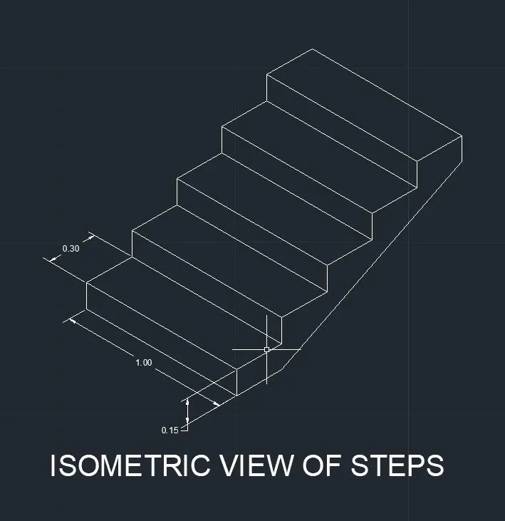
- Isometric view of steps
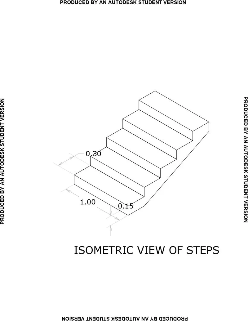
Aim: To draw the isometric view of the steps as shown in figure
Procedure:
Step 1
- In command box type “ds” drafting settings window is appeared
- Select “isometric snap” from snap type tile and click ok
- Click F5 to switch between isoplanes
Step 2
- Choose line tool from tool box
- Specify the first point
- select isoplane left and move the cursor left side and give length as 1 unit
- move the cursor upwards and give length 0.15 units
- move the cursor left and give length 1 units
- then press “c” to close the box
Step 2
- Choose line tool from tool box
- Specify the first point at left top corner
- select isoplane top and move the cursor right side and give length as 0.3 unit
- move the cursor downwards and give length 1unit
- move the cursor to right top point of rectangle and press enter
- press esc
Step3
- choose copy tool
- select the objected created
- click at the endpoint of object
- choose array in command box
- and enter 5 in command box to copy 5 same objects at same distances
- Then move the cursor to top point and click
- Press esc
Step 4
- Select isoplane right
- Choose line tool
- Click at top corner of object and drag the cursor downwards and give length as 0.15 and press esc
- Choose line tool
- Click at bottom corner of object and drag the cursor right side and give length as 0.3
- Then drag the cursor to previous line and click
- Then press esc
Step 5
- Give the all dimensions using "DIM" in command box
- By using "Text" commant the drawing given to the titles
Result: The given drawing is successfully drawn by given dimensions which is shown below
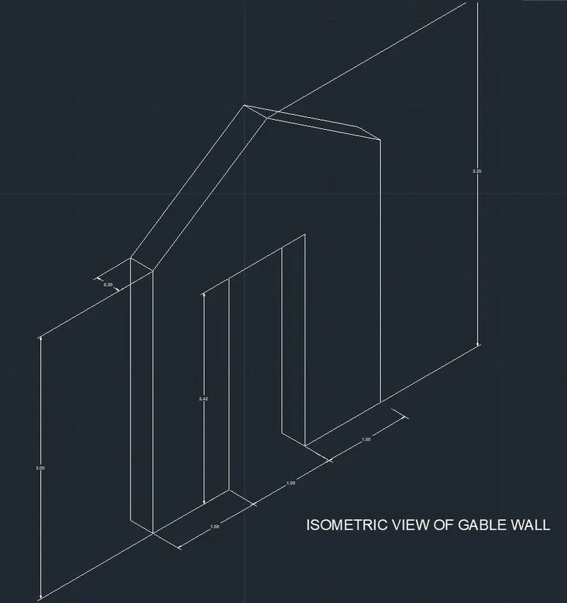
- Isometric view of gable wall
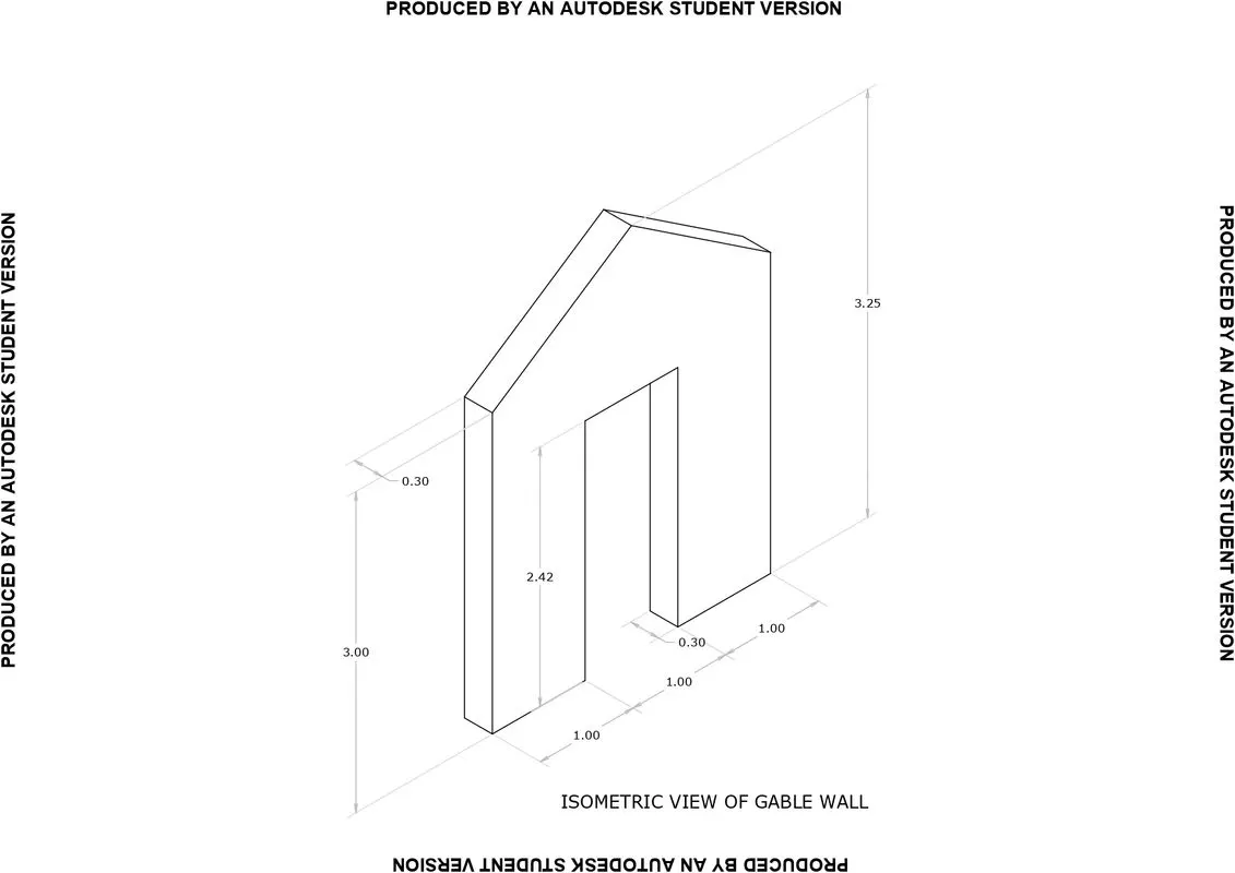
Aim: To draw the isometric view of gable wall as given
Procedure:
Step 1
- In command box type “ds” drafting settings window is appeared
- Select “isometric snap” from snap type tile and click ok
- Click F5 to switch between isoplanes
Step 2
- Choose line tool from tool box
- Specify the first point
- select isoplne right and move the cursor downside and give length as 3 unit
- move the cursor left side and length as 1 unit
- move the cursor up side and length as 2.42 unit
- move the cursor left side and length as 1 unit
- move the cursor down side and length as 2.42 unit
- move the cursor left side and length as 1 unit
- move the cursor up side and length as 3 unit
Step 3
- Choose line tool from tool box
- Specify the midpoint of top line and move the cursor upwards and give length as 1.58 units
- Then connect two ends with that point (ortho off)
- After that delete unwanted lines
Step 4
- Choose line tool from tool box
- select isoplne left
- start with required corner points move the cursor left side and give length as 0.3 units
- then join the lines and press esc
Step 5
- Give the all dimensions using "DIM" in command box
- By using "Text" commant the drawing given to the titles
Result: The given drawing is successfully drawn by given dimension swhich is shown below