Creating Bar Bending schedule, Different Door types, and Creation of standard drawing templates using AutoCad
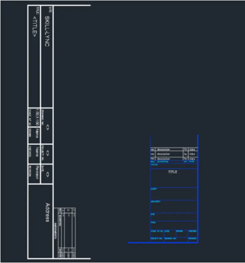
- 1. Make the templates as given in Pictures. Take the size of the title block as per industry standards or you can suppose it as per the size of the paper. Utilize text and attributes wherever needed. After generating the title block you require to save it as a block with names: Custom1_titleblock and Custom2_titleblock, accordingly.
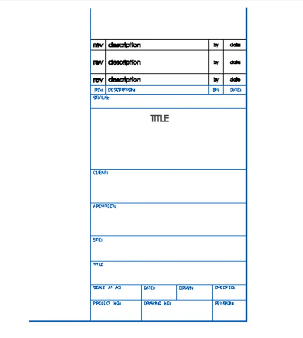
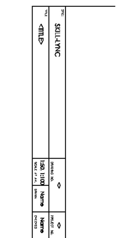
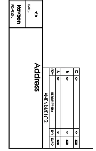
AIM: To make the templates and require taking the size of title block as per industry standards. And require saving them as a block names as Custom1_titlebox and Custom2_titlebox.
INTRODUCTION:
- Sketching template files are sketching’s that store styles, settings, layers, and layouts in a sketching including title blocks.
- When you make a new sketching based on a sketching template, the new sketching gets a copy of the styles in the template, but it is a one-time copy.
Command utilized:
- Limits command
- Single Text command
- Line command
- Dimlinear command
- Trim command
- Object snap command
- Offset command
- Units command
- Dimstyle command
- Extend command
- Block command
PROCEDURE: Custom1_title block
STEP-1
- Go to START MENU, choose AutoCAD.
- In the Command line type in: STARTUP [ENTER]
- Enter ’UNITS’ command in the command tab.
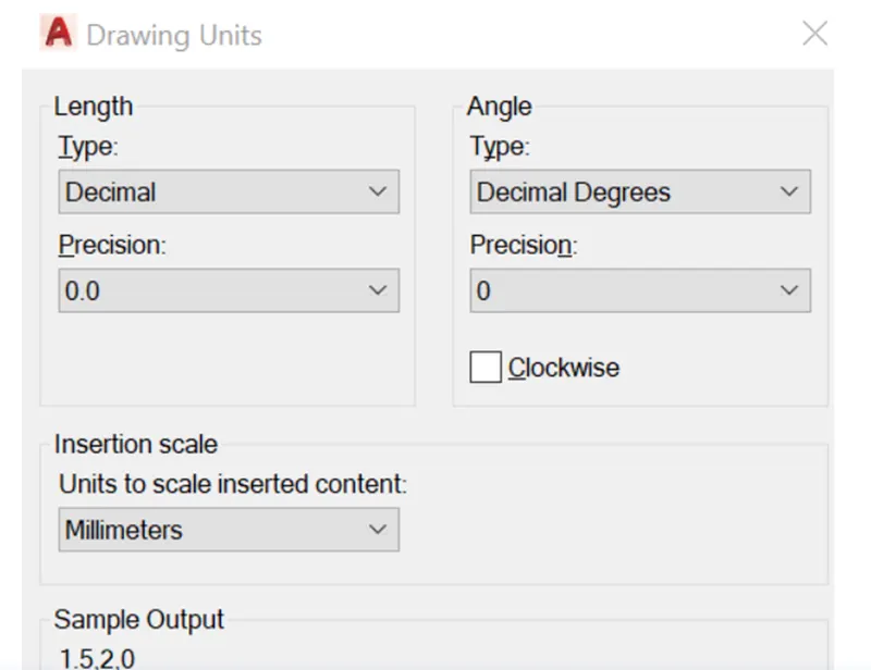
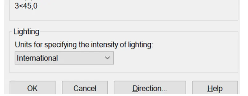
- In the Sketching Units dialog box, choose 'Decimal' in Type: ' 0.0' in Precision; and 'Millimeters' in Insertion scale.
- Click on 'OK'.
- Set the limits by entering LIMITS in the Command tab. The lower-left corner is specified as 0, 0; and the upper-right corner is specified as 1000, 1000.
STEP-2
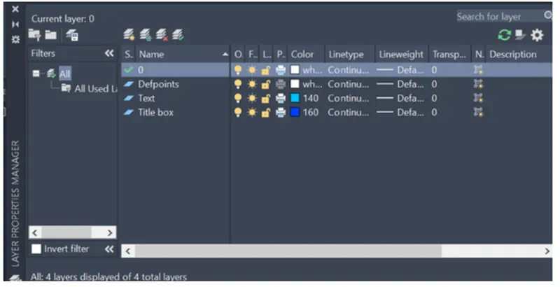
- Click on layer properties in the layer panel on the ribbon.
- Click on new layer to make the following layers text and title box.
- Define deferent colour for the different layers and then close the layer properties manager dialog box.
STEP-3
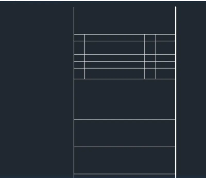
- Choose the Rectangle tool by entering 'REC' command in the command tab.
- Define the start point, Enter @75,150.
- Thumb Esc.
- Enter X in the command tab.
- Choose the rectangle made and explode it.
- Choose the Line tool by entering 'L' command in the command tab.
- Sketch lines to form the different sections within the box.
- Thumb Esc.
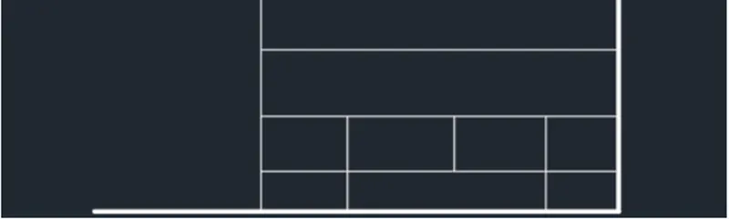
STEP-4
- Enter 'MTEXT' command in the command line.
- Define the start point of text as needed.
- Give text height as 4.
- Copy the text box to wherever necessary.
- Enter ED in the command prompt and edit the text boxes as needed.
- Click Enter and thumb Esc.
- Assign the different lines and text to their respective layer.
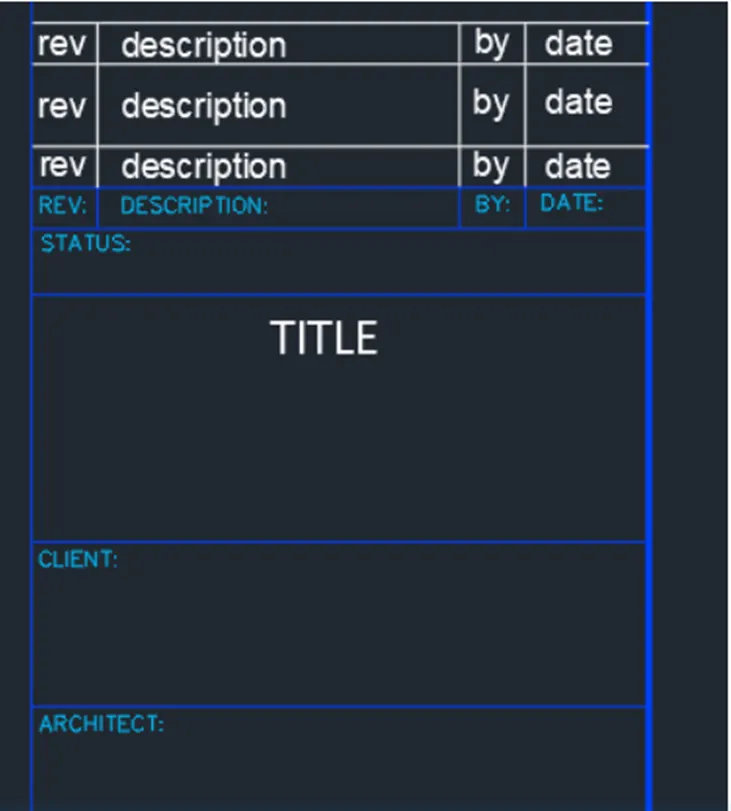
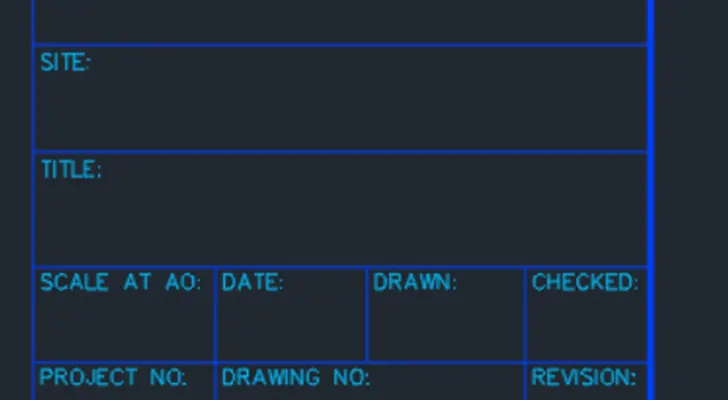
STEP-5
- Enter B in the command prompt.
- In the Block Definition dialogue box, type in the name of the block as Custom1_titleblock, pick the base point as the ottom right corner of the block, choose the entire title box made and thumb Enter.
- Click OK.
Custom2_title block
STEP-1
- In the same sketching as the Custom1_titleblock.
- Choose the Rectangle tool by entering 'REC command in the command tab.
- Define the start point, Enter @500, 50.
- Thumb Esc.
- Enter X in the command tab.
- Choose the rectangle made and explode it.
- Choose the Line tool by entering 'L' command in the command tab.
- Sketch lines to form the different sections within the box.
- Choose the lines, go to properties, and change Line weight to 0.30 mm.
- Thumb Esc.
- Again, Choose the Rectangle tool by entering 'REC command in the command tab.
- Define, the start point, then for dimension Enter @80, 35.
- Thumb Esc.
- Enter X in the command tab.
- Choose the rectangle made and explode it.
- Choose the Line tool by entering 'L' command in the command tab.
- Sketch lines to form the different sections within the box.
- Thumb Esc.
- Trim, Extend and Erase the not needed lines.
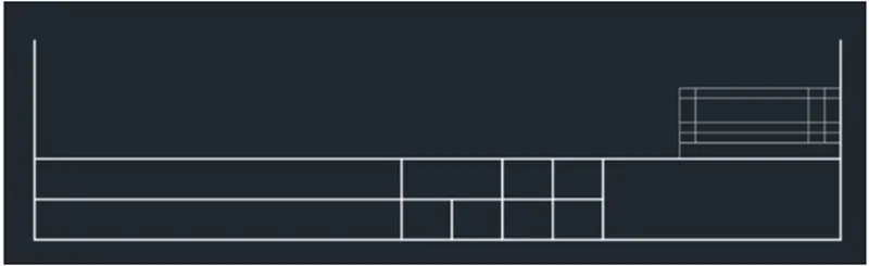
STEP-2
- Enter 'MTEXT' command in the command line.
- Define the start point of text as needed.
- Give text height as 6.
- Copy the text box to wherever necessary.
- Enter ED in the command prom and edit the text boxes as needed.
- Click Enter and thumb Esc.
- Enter ATTDEF in the command prompt.
- Type in R1C1 in Tag, First row in Prompt, and C in Default.
- Click OK.
- Repeat the same method for all rows and columns in the smaller box.
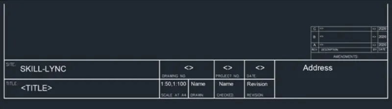
STEP-3
- Enter B in the command prompt.
- In the Block Definition dialogue box, type in the name of the block as Custom2_titleblock, pick the base point as the bottom right corner the block, Choose the entire title box made and thumb Enter.
- Click OK.
RESULT:
Q.2 Make the doors type for warehouse as given in the Picture. You require making each door type as per standard size or given dimensions. Make the blocks of this door type after generating them.
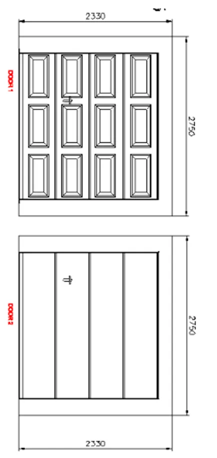
AIM: To make the doors type for warehouse and require to make each door type as per standard size and to make the blocks of door type after generating them.
INTRODUCTION:
- Doors are sketch in plan view as a heavy line in small-scale sketching’s, or as a double line, to indicate their thickness, in larger- scaled plans.
- A swing door has a thinner curved line sketch to denote the direction of its swing.
- The sketching’s of doors are sketch by the architects in the construction projects.
Command utilized:
- Limits command
- Single Text command
- Line command
- Dimlinear command
- Trim command
- Line weight command
- Line type command
- Object snap command
- Offset command
- Units command
- Dimstyle command
- Extend command
- Block command
PROCEDURE:
- DOOR1:
STEP-1
- Go to START MENU, choose AutoCAD
- In the Command line type in: STARTUP [ENTER]
- Enter 'UNITS' command in the command tab.
- In the Sketching Units dialog box, choose 'Decimal' in Type: ' O' in Precision; and 'Millimeters' in Insertion scale.
- Click on 'OK'.
- Set the limits by entering LIMITS in the Command tab. The lower-left corner is specified as 0, 0; and the upper-right corner is specified as 10000, 10000.
STEP-2
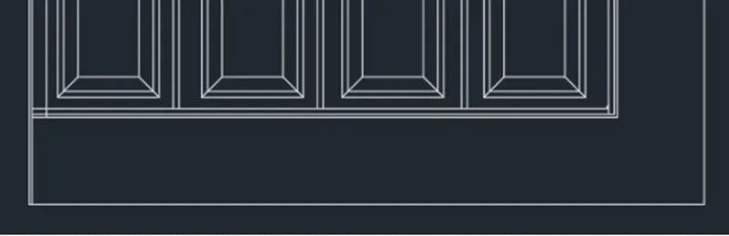
- Choose the Rectangle tool by entering 'REC' command in the command tab.
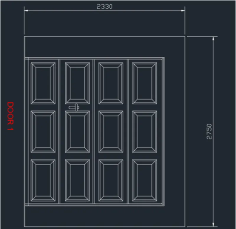
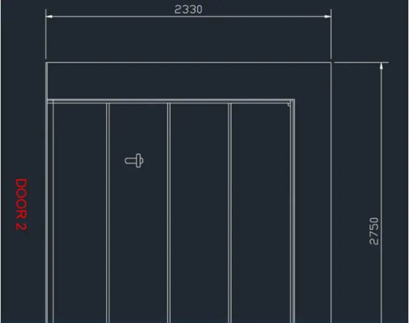
- Define the start point, Enter @2330, 2750.
- Thumb Esc.
- Enter X in the command tab.
- Choose the rectangle made and explode it.
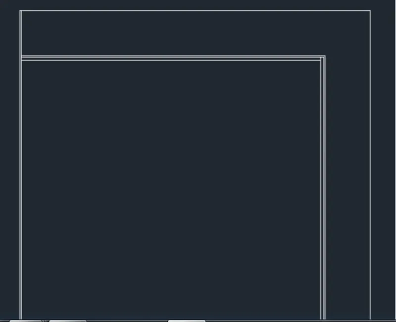
- Choose the Offset tool by entering 'O' in the command tab.
- Define an offset distance of 10, choose the left side of the rectangle and then click on the inside.
- Repeat Offset, define distance as 300, and then offset the other three sides of the rectangle.
- Repeat offset, define distance as 10, and then offset the three sides of the smaller inner rectangle.
- Repeat offset, define distance as 20, and then offset the previous three off-setted lines.
- Thumb Esc to cancel the OFFSET command.
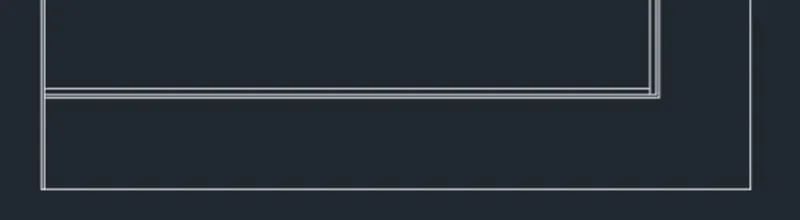
- Choose the Trim tool by entering 'TR' command in the command tab.
- Thumb ENTER.
- Choose Edge option; and click on No Extend.
- Choose the not needed lines.
- Thumb 'Esc' to cancel the TRIM command.
STEP-3
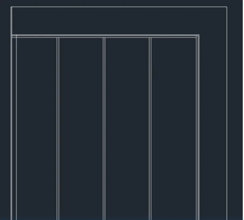
- Choose the Divide tool from the sketch panel.
- Choose the inner edge of the smaller rectangle, and enter number of segments as 4.
- Choose the Line tool by entering LINE' command in the command tab.
- Sketch vertical lines from each section point.
- Thumb Esc.
- Remove the section points.
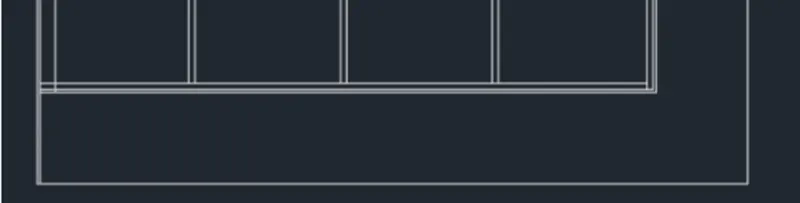
- Choose the Offset tool by entering 'O' in the command tab.
- Define an offset distance of 10, choose the section lines and click on either sides.
- Repeat offset, define a distance of 50, choose the left inner edge of the smaller rectangle and click inside.
- Thumb Esc to cancel the OFFSET command.
- Choose the not needed lines and Erase them.
STEP-4
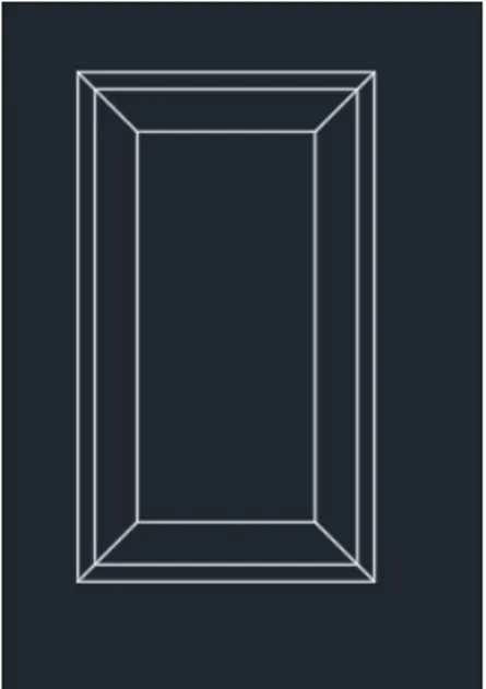
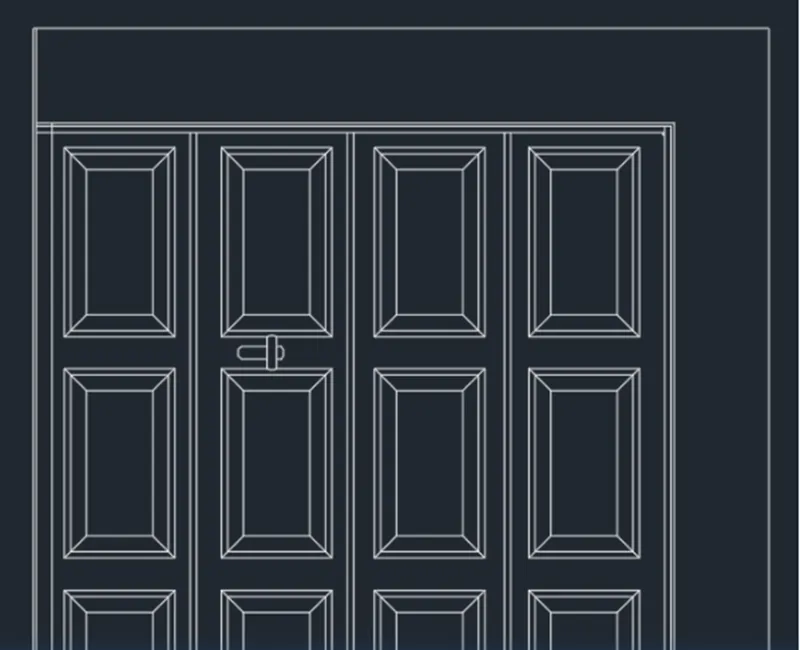
- Choose the Rectangle tool by entering 'REC' command in the command tab.
- Define the start point, Enter @350,600.
- Thumb Esc.
- Enter X in the command tab.
- Choose the rectangle made and explode it.
- Choose the Offset tool by entering 'O' in the command tab.
- Define an offset distance of 20, choose all the sides of the rectangle and then click on the inside.
- Repeat Offset, define distance as 50, and choose all the previous off-setted lines and then click on the inside.
- Thumb Esc to cancel the OFFSET command.
- Choose the Trim tool by entering 'TR' command in the command tab.
- Thumb ENTER.
- Choose Edge option; and click on No Extend.
- Choose the not needed lines.
- Thumb 'Esc' to cancel the TRIM command.
- Choose the Line tool by entering 'LINE' command in the command tab.
- Sketch diagonal lines from each corner point.
- Thumb Esc.
- Choose the Copy tool by entering 'CO' command in the command tab.
- Copy the pattern made above and paste to the wanted locations.
- Thumb Esc.
- Choose the Polyline tool from the Ribbon.
- Sketch the door handle as given.
- Thumb Esc.
STEP-5
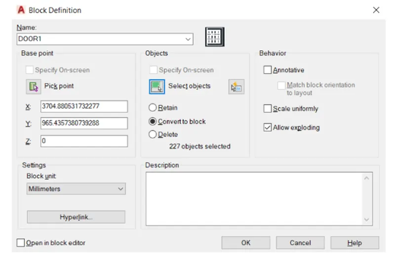
- Enter B in the command prompt.
- In the Block Definition dialogue box, type in the name of the block as DOOR1, pick the base point as the bottom right corner of the door, Choose the object maked and thumb Enter.
- Click OK.
STEP-6
- Enter 'DST' command in the command tab to open the Dimension Style Manager the Symbols and Arrows option change the Arrow size to 60. Dialog box.
- Click on the Modify tab.
- Under the Lines option change the colour of the dimension and extension lines.
- Under the Symbols and Arrows option change the Arrow size to 60.
- Click OK. Then click on Set Current and Close the dialog box.
- Choose the Dimension tool by entering 'DIM' in the command line.
- Choose the first point and second point of the object to be measured, then drag the dimension line to the wanted location. Repeat for all the objects to be measured.
- Enter 'MTEXT' command in the command line.
- Define the start point of text as needed.
- Enter text height as 80.
- Copy the text box to wherever necessary.
- Enter ED in the command prompt and edit the text boxes as needed.
- Click Enter and thumb Esc.
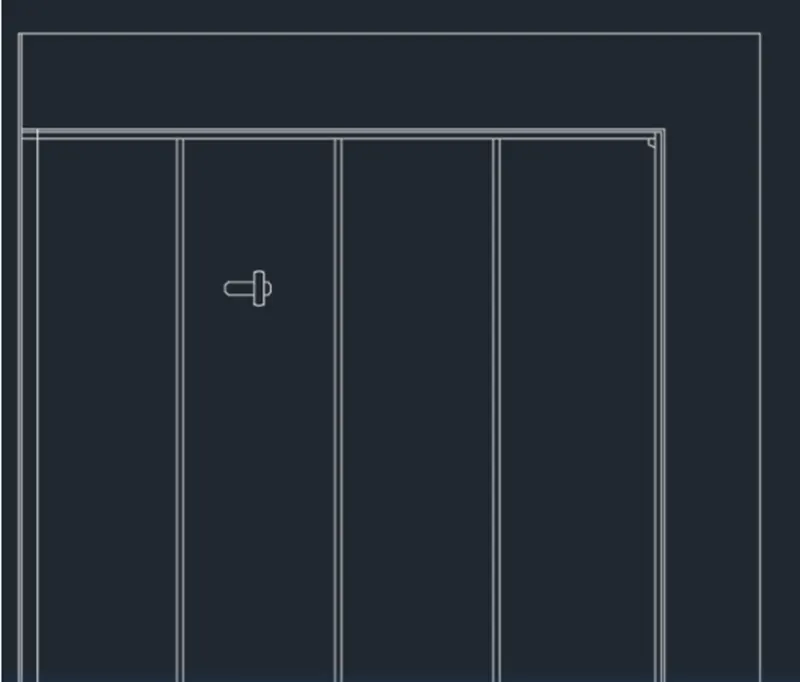
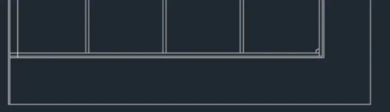
- DOOR 2:
STEP-1
- Choose the DOOR1 block and click on the Explode Icon on the Ribbon.
- Choose the Copy tool by entering 'CO' command in the command tab.
- Copy the door frame, and sections (without the patterns) of DOOR1.
- Paste it right below Door1.
- Thumb Esc.
STEP-2
- Enter B in the command prompt.
- In the Block Definition dialogue box, type in the name of the block as DOOR2, pick the base point as the bottom right corner of the door, choose the object made and thumb Enter.
- Click OK.
STEP-3
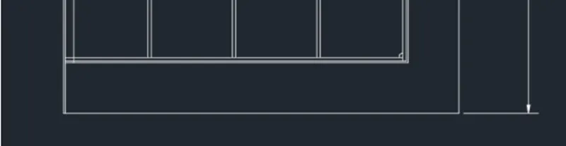
- Choose the Dimension tool by entering 'DIM' in the command line.
- Choose the first point and second point of the object to be measured, and then drag the dimension line to the wanted location. Repeat for all the objects to be measured.
- Enter 'MTEXT' command in the command line.
- Define the start point of text as needed.
- Enter text height as 80.
- Copy the text box to wherever necessary.
- Enter ED in the command prompt and edit the text boxes as needed.
- Click Enter and thumb Esc.
RESULT:
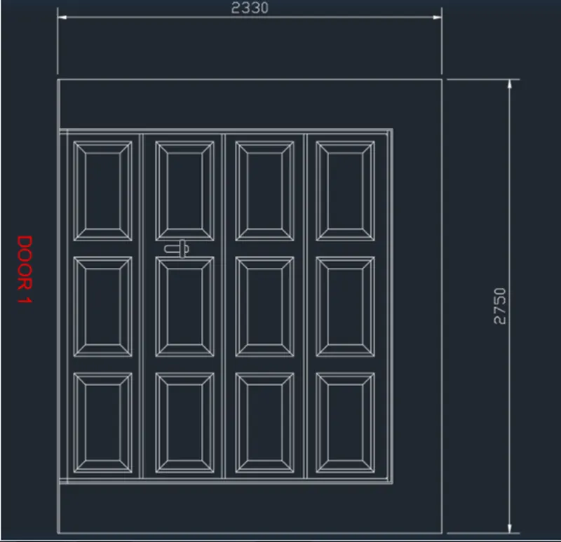
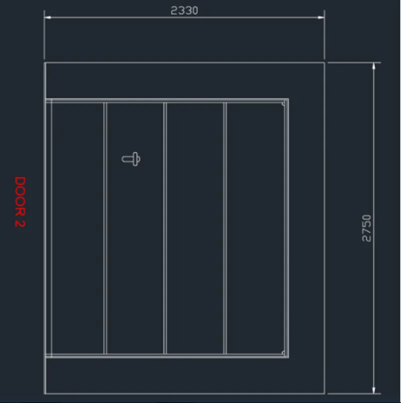
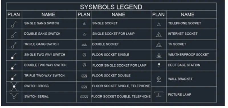
Q.3 Make each symbol as a block with the name given in the legend. After generating the blocks arrange them in the legend as given in the Picture.
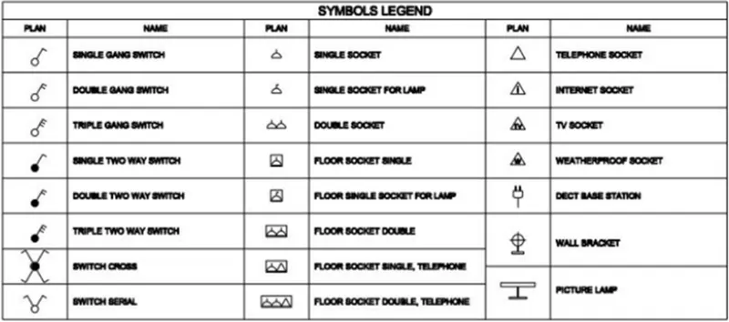
AIM: To make the electric symbols as block with the name and to make the blocks and arrange them in the legend.
INTRODUCTION:
- Electrical symbols are utilized for universal recognition of the building plan by different persons who will be working on the construction.
- Not all possible electric symbols utilized on a certain plan, so the symbols utilized in the current home plan are included to a legend.
- The electrical home plan may be added as a separate document to a complete set.
Command utilized:
- Limits command
- Single Text command
- Line command
- Dimlinear command
- Trim command
- Object snap command
- Offset command
- Units command
- Dimstyle command
- Block command
- Extend command.
- LW command
- LT command
PROCEDURE:
STEP-1
- Go to START MENU, choose AutoCAD 2022.
- In the Command line type in: STARTUP [ENTER]
- Enter 'UNITS' command in the command tab.
- In the Sketching Units dialog box, choose 'Decimal' in Type: ' 0.0' in Precision; and 'Millimeters in Insertion scale.
- Click on 'OK'.
- Set the limits by entering LIMITS in the Command tab. The lower-left corner is specified as 0, 0; and the upper-right corner is specified as 10000, 10000.
STEP-2
- Choose the Circle tool by entering 'C' command in the command tab.
- Define the center and enter radius circle as radius 50.
- Choose the Line tool by entering 'LINE' command in the command tab, and turn Ortho off.
- Sketch an inclined line of length 100 from the circumference of the circle, and another line of length 50.
- Thumb Esc.

- Enter B in the command prompt.
- In the Block Definition dialogue box, type in the name of the block as SINGLE GANG SWITCH, pick the base point as the center of the circle. Choose the object made and thumbs Enter.
- Click OK.
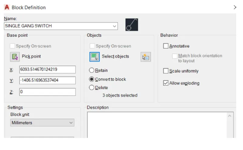
STEP-3
- Choose the Circle tool by entering 'C' command in the command tab.
- Define the center and enter radius circle as radius 50.
- Choose the Line tool by entering LINE' command in the command tab, and turn Ortho off.
- Sketch an inclined line of length 100 from the circumference of the circle, and another line of length 50.
- Thumb Esc.
- Enter O in the command prompt, define distance as 30. Choose the line of length 50 and offset it.
- Thumb Esc.
- Enter B in the command prompt.
- In the Block Definition dialogue box, type in the name of the block as DOUBLE GANG SWITCH, pick the base point as the center of the Choose the object made and thumb Enter.
- Click OK.

STEP-4
- Choose the Circle tool by entering C command in the command tab.
- Define the center and enter radius circle as radius 50.
- Choose the Line tool by entering LINE command in the command tab, and turn Ortho off.
- Sketch an inclined line of length 100 from the circumference of the circle, and another line of length 50.
- Thumb Esc.
- Enter O in the command prompt, define distance as 30, choose the line of length 50 and offset it twice.
- Thumb Esc.
- Enter B in the command prompt.
- In the Block Definition dialogue box, type in the name of the block as TRIPLE GANG SWITCH, pick the base point as the center of the circle Choose the object made and thumb Enter.
- Click OK.

STEP-5
- Choose the Circle tool by entering 'C' command in the command tab.
- Define the center and enter radius circle as radius 50.
- Enter O in the command prompt, define distance as 15, choose the circle and click inside.
- Thumb Esc.
- Enter H, choose the solid pattern and pick point inside the smaller circle.
- Thumb Esc.
- Choose the Line tool by entering 'LINE' command in the command tab, and turn Ortho off.
- Sketch an inclined line of length 100 from the circumference of the circle, and another line of length 50.
- Thumb Esc.
- Enter B in the command prompt.
- In the Block Definition dialogue box, type in the name of the block as SINGLE TWO WAY SWITCH, pick the base point as the center of the circle, choose the object made and thumb Enter.
- Click OK.

STEP-6
- Choose the Circle tool by entering 'C' command in the command tab.
- Define the center and enter radius circle as radius 50.
- Enter O in the command prompt, define distance as 15, choose the circle and click inside.
- Thumb Esc.
- Enter H, choose the solid pattern and pick point inside the smaller circle.
- Thumb Esc.
- Choose the Line tool by entering 'LINE' command in the command tab, and turn Ortho off.
- Sketch an inclined line of length 100 from the circumference of the circle, and another line of length 50.
- Thumb Esc.
- Enter O in the command prompt, define distance as 30. Choose the line of length 50 and offset it.
- Thumb Esc.
- Enter B in the command prompt.
- In the Block Definition dialogue box, type in the name of the block as DOUBLE TWO WAY SWITCH, pick the base point as the center of the circle, choose the object made and thumb Enter.
- Click OK.

STEP-7
- Choose the Circle tool by entering 'C' command in the command tab.
- Define the center and enter radius circle as radius 50. Enter O in the command prompt.
- Define distance as 15, choose the circle and click inside.
- Thumb Esc.
- Enter H, choose the solid pattern and pick point inside the smaller circle.
- Thumb Esc.
- Choose the Line tool by entering 'LINE' command in the command tab, and turn Ortho off.
- Sketch an inclined line of length 100 from the circumference of the circle, and another line of length 50.
- Thumb Esc.
- Enter O in the command prompt, define distance as 30. Choose the line of length 50 and offset it twice.
- Thumb Esc.
- Enter B in the command prompt.
- In the Block Definition dialogue box, type in the name of the block as TRIPLE TWO WAY SWITCH, pick the base point as the center of the circle, choose the object made and thumb Enter.
- Click OK.

STEP-8
- Choose the Circle tool by entering 'C' command in the command tab.
- Define the center and enter radius circle as radius 50. Enter O in the command prompt.
- Define distance as 15, choose the circle and click inside.
- Thumb Esc.
- Enter H, choose the solid pattern and pick point inside the smaller circle.
- Thumb Esc.
- Choose the Line tool by entering 'LINE' command in the command tab, and turn Ortho off.
- Sketch an inclined line of length 100 from the circumference of the circle, and another line of length 50.
- Thumb Esc.
- Rotate and copy the lines to three other locations.
- Thumb Esc.
- Enter B in the command prompt.
- In the Block Definition dialogue box, type in the name of the block as SWITCH CROSS, pick the base point as the center of the circle, choose the object made and thumb Enter.
- Click OK.

STEP-9
- Choose the Circle tool by entering 'C' command in the command tab.
- Define the center and enter radius circle as radius 50.
- Choose the Line tool by entering 'LINE' command in the command tab, and turn Ortho off.
- Sketch an inclined line of length 100 from the circumference of the circle, and another line of length 50.
- Thumb Esc.
- Rotate and copy the lines to three other locations.
- Thumb Esc.
- Enter B in the command prompt.
- In the Block Definition dialogue box, type in the name of the block as SWITCH SERIAL, pick the base point as the center of the circle, choose the object made and thumb Enter.
- Click OK.

STEP-10
- Choose the Circle tool by entering 'C' command in the command tab.
- Define the center and enter radius circle as radius 50.
- Choose the Line tool by entering 'LINE' command in the command tab.
- Sketch two lines through the center of the circle.
- Thumb Esc.
- Choose the Trim tool by entering 'TR' command in the command tab.
- Thumb ENTER.
- Choose Edge option; and click on No Extend.
- Choose the not needed lines.
- Thumb 'Esc' to cancel the TRIM command.
- Enter B in the command prompt.
- In the Block Definition dialogue box, type in the name of the block as SINGLE SOCKET, pick the base point as the center of the circle, choose the object made and thumb Enter.
- Click OK.
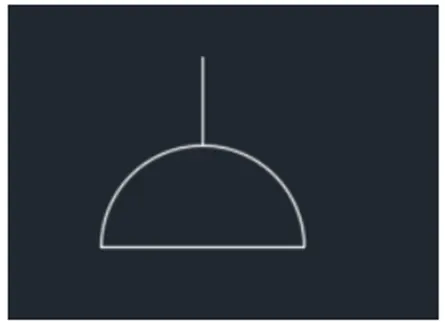
STEP-11
- Choose the Circle tool by entering 'C' command in the command tab.
- Define the center and enter radius circle as radius 50.
- Choose the Line tool by entering 'LINE' command in the command tab.
- Sketch two lines through the center of the circle.
- Thumb Esc.
- Choose the Trim tool by entering 'TR' command in the command tab.
- Thumb ENTER.
- Choose Edge option; and click on No Extend.
- Choose the not needed lines.
- Thumb 'Esc' to cancel the TRIM command.
- Choose the Line tool by entering 'LINE' command in the command tab.
- Sketch a line of length 30 from the top of the vertical line.
- Thumb Esc.
- Enter B in the command prompt.
- In the Block Definition dialogue box, type in the name of the block as SINGLE SOCKET FOR LAMP, pick the base point as the center of the circle, choose the object made and thumb Enter.
- Click OK.

STEP-12
- Choose the Circle tool by entering 'C' command in the command tab.
- Define the center and enter radius circle as radius 50.
- Choose the Line tool by entering 'LINE' command in the command tab.
- Sketch two lines through the center of the circle.
- Thumb Esc.
- Choose the Trim tool by entering 'TR' command in the command tab.
- Thumb ENTER.
- Choose Edge option; and click on No Extend.
- Choose the not needed lines.
- Thumb 'Esc' to cancel the TRIM command.
- Enter CO in the prompt and copy the socket following to it.
- Thumb Esc.
- Enter B in the command prompt.
- In the Block Definition dialogue box, type in the name of the block as DOUBLE SOCKET FOR LAMP, pick the base point as the center of the circle, choose the object made and thumb Enter.
- Click OK.
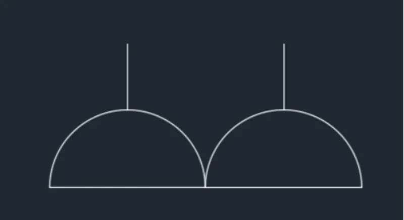
STEP-13
- Choose the Circle tool by entering 'C' command in the command tab.
- Define the center and enter radius circle as radius 50.
- Choose the Line tool by entering 'LINE' command in the command tab.
- Sketch two lines through the center of the circle.
- Thumb Esc.
- Choose the Trim tool by entering 'TR' command in the command tab.
- Thumb ENTER.
- Choose Edge option; and click on No Extend.
- Choose the not needed lines.
- Thumb 'Esc' to cancel the TRIM command.
- Enter REC in the prompt.
- Sketch a rectangle around the socket symbol.
- Enter B in the command prompt.
- In the Block Definition dialogue box, type in the name of the block as FLOOR SOCKET SINGLE, pick the base point as the center of the circle, choose the object made and thumb Enter.
- Click OK.
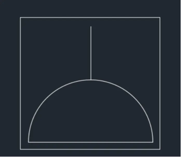
STEP-14
- Choose the Circle tool by entering 'C' command in the command tab.
- Define the center and enter radius circle as radius 50.
- Choose the Line tool by entering 'LINE' command in the command tab.
- Sketch two lines through the center of the circle.
- Thumb Esc.
- Choose the Trim tool by entering 'TR' command in the command tab.
- Thumb ENTER.
- Choose Edge option; and click on No Extend.
- Choose the not needed lines.
- Thumb 'Esc' to cancel the TRIM command.
- Enter CO in the prompt and copy the socket following to it.
- Thumb Esc.
- Enter REC in the prompt.
- Sketch a rectangle around the socket symbol.
- Enter B in the command prompt.
- In the Block Definition dialogue box, type in the name of the block as FLOOR SOCKET DOUBLE, pick the base point as the center of the circle, choose the object made and thumb Enter.
- Click OK.
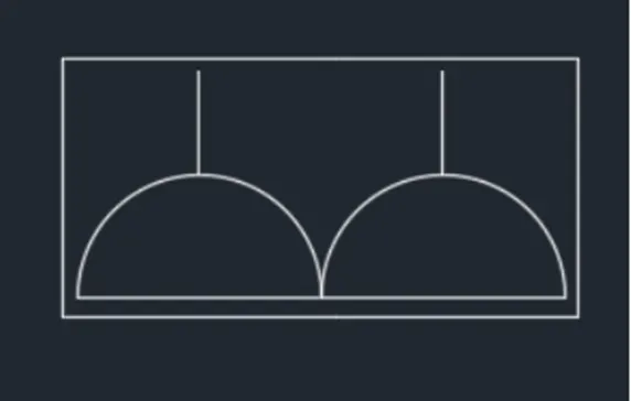
STEP-15
- Choose the Circle tool by entering 'C' command in the command tab.
- Define the center and enter radius circle as radius 50.
- Choose the Line tool by entering 'LINE' command in the command tab.
- Sketch two lines through the center of the circle.
- Thumb Esc.
- Choose the Trim tool by entering 'TR' command in the command tab.
- Thumb ENTER.
- Choose Edge option; and click on No Extend.
- Choose the not needed lines.
- Thumb 'Esc' to cancel the TRIM command.
- Choose the Line tool by entering LINE' command in the command tab.
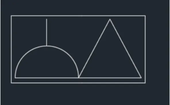
- Sketch a triangle adjacent to the socket symbol.
- Thumb Esc.
- Enter REC in the prompt.
- Sketch a rectangle around the socket symbol.
- Enter B in the command prompt.
- In the Block Definition dialogue box, type in the name of the block as FLOOR SOCKET SINGLE, TELEPHONE picks the base point as the center of the circle, Choose the object made and thumb Enter.
- Click OK.
STEP-16
- Choose the Circle tool by entering 'C' command in the command tab.
- Define the center and enter radius circle as radius 50.
- Choose the Line tool by entering 'LINE' command in the command tab.
- Sketch two lines through the center of the circle.
- Thumb Esc.
- Choose the Trim tool by entering 'TR' command in the command tab.
- Thumb ENTER.
- Choose Edge option; and click on No Extend.
- Choose the not needed lines.
- Thumb 'Esc' to cancel the TRIM command.
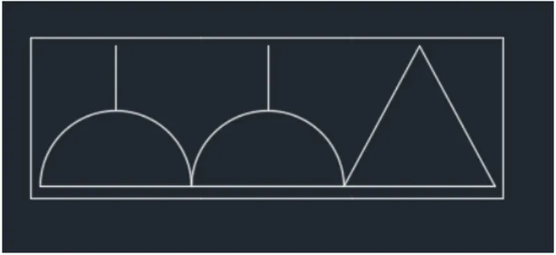
- Enter CO in the prompt and copy the socket following to it.
- Enter Choose the Line tool by entering LINE' command in the command tab.
- Thumb Esc.
- Enter REC in the prompt.
- Sketch a rectangle around the socket symbol.
- Enter B in the command prompt.
- In the Block Definition dialogue box, type in the name of the block as FLOOR SOCKET DOUBLE, TELEPHONE picks the base point as the center of the circle, Choose the object made and thumb Enter.
- Click OK.
STEP-17
- Choose the Line tool by entering LINE' command in the command tab.
- Sketch a triangle symbol.
- Prss Esc.
- Click Enter and thumb Esc.
- Enter B in the command prompt.
- In the Block Definition dialogue box, type in the name of the block as TELEPHONE SOCKET, pick the base point as the center of the circle, choose the object made and thumb Enter.
- Click OK.

STEP-18
- Choose the Line tool by entering LINE' command in the command tab.
- Sketch a triangle symbol.
- Prss Esc.
- Enter 'MTEXT' command in the command line.
- Define the start point of text as needed.
- Enter text height as 30.
- Copy the text box inside the triangle.
- Click Enter and thumb Esc.
- Enter B in the command prompt.
- In the Block Definition dialogue box, type in the name of the block as INTERNET SOCKET, pick the base point as the center of the circle, choose the object made and thumb Enter.
- Click OK.

STEP-19
- Choose the Line tool by entering LINE' command in the command tab.
- Sketch a triangle symbol.
- Thumb Esc.
- Enter 'MTEXT' command in the command line.
- Define the start point of text as needed.
- Enter text height as 30.
- Copy the text box inside the triangle.
- Click Enter and thumb Esc.
- Enter B in the command prompt.
- In the Block Definition dialogue box, type in the name of the block as TV SOCKET, pick the base point as the center of the circle, choose the object made and thumb Enter.
- Click OK.

STEP-20
- Choose the Line tool by entering LINE' command in the command tab.
- Sketch a triangle symbol.
- Prss Esc.
- Enter 'MTEXT' command in the command line.
- Define the start point of text as needed.
- Enter text height as 30.
- Copy the text box inside the triangle.
- Click Enter and thumb Esc.
- Enter B in the command prompt.
- In the Block Definition dialogue box, type in the name of the block as WEATHERPROOF SOCKET, pick the base point as the center of the circle, choose the object made and thumb Enter.
- Click OK.

STEP-21
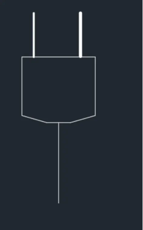
- Choose the Polyline tool by entering 'PLINE' command in the command tab.
- Sketch the plug head.
- Thumb Esc.
- Choose the Line tool by entering 'LINE' command in the command tab.
- Sketch two lines representing the plug pins.
- Thumb Esc.
- Choose the lines, go to properties and change line weight to 0.35 mm.
- Choose the Line tool by entering 'LINE' command in the command tab.
- Sketch a line representing the cable.
- Thumb Esc.
- Enter B in the command prompt.
- In the Block Definition dialogue box, type in the name of the block as DECT BASE STATIO, pick the base point as the center of the circle, choose the object made and thumb Enter.
- Click OK.
STEP-22
- Login| Sign Up
- Choose the Circle tool by entering 'C' command in the command tab.
- Define the center and enter radius circle as radius 60.
- Choose the Line tool by entering 'LINE' command in the command tab.
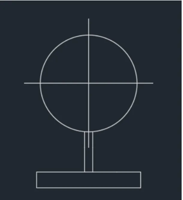
- Sketch two lines through the center of the circle.
- Thumb Esc.
- Choose the Trim tool by entering 'TR' command in the command tab..
- Thumb ENTER.
- Choose Edge option; and click on No Extend.
- Choose the not needed lines.
- Thumb 'Esc' to cancel the TRIM command.
- Choose the Line tool by entering LINE' command in the command tab.
- Sketch the bottom portion of the bracket.
- Thumb Esc.
- Enter B in the command prompt.
- In the Block Definition dialogue box, type in the name of the block as WALL BRACKET, pick the base point as the center of the circle, choose the object made and thumb Enter.
- Click OK.
STEP-23
- Choose the Rectangle tool by entering 'REC command in the command tab.
- Define the start point, Enter @250, 30.
- Thumb Esc.
- Choose the Line tool by entering LINE' command in the command tab.
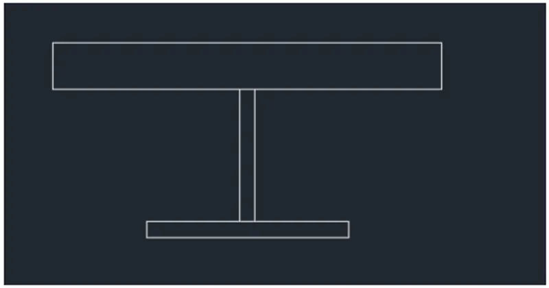
- Sketch the bottom portion of the Lamp.
- Enter 85 pointing the crosshair downwards.
- Enter 60 pointing the crosshair right.
- Enter 30 pointing the crosshair downwards.
- Enter 130 pointing the crosshair left.
- Enter 30 pointing the crosshair upwards.
- Click 'Close’
- Thumb Esc.
- Enter B in the command prompt.
- In the Block Definition dialogue box, type in the name of the block as PICTURE LAMP, pick the base point as the center of the circle, choose the object made and thumb Enter.
- Click OK.
STEP-24
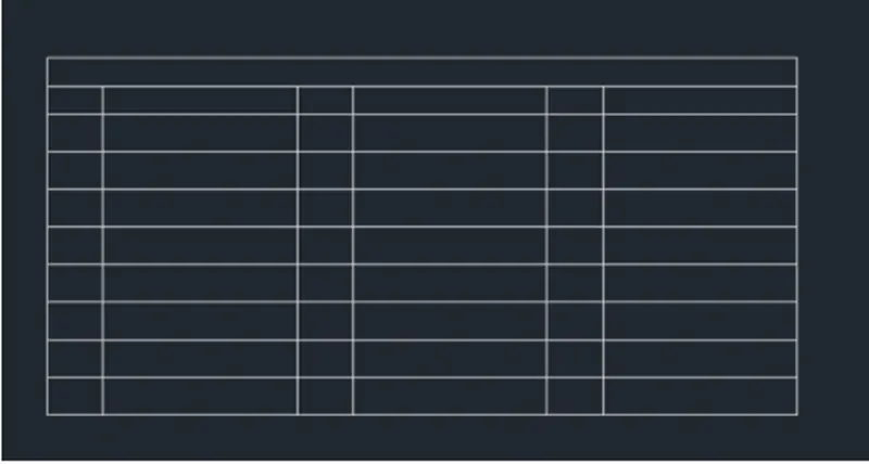
- Choose the Rectangle tool by entering 'REC command in the command tab.
- Define the start point, Enter @8000, 3800.
- Thumb Esc.
- Enter X in the command tab.
- Choose the rectangle made and explode it.
- Choose the Offset tool by entering 'O' in the command tab.
- Define an offset distance of 300, choose top line and offset it twice.
- Repeat Offset, define distance as 400, and choose the previous offsetted line and offset it 7 times.
- Thumb Esc to cancel the OFFSET command.
- Choose the Offset tool by entering O' in the command tab.
- Define an offset distance of 600, choose left hand line and offset it.
- Repeat Offset, define distance as 2066, and choose the previous offsetted line and offset it.
- Thumb Esc to cancel the OFFSET command.
- Choose the Trim tool by entering 'TR' command in the command tab.
- Thumb ENTER.
- Choose Edge option; and click on No Extend.
- Choose the not needed lines.
- Thumb 'Esc' to cancel the TRIM command.
- Choose the Line tool by entering LINE' command in the command tab.
- Sketch diagonal lines from each corner point.
- Thumb Esc.
STEP-25
- Enter 'i' command in the command line.
- In the Insert dialog box, choose the symbols made in steps 2 - 22 and insert them into the table one by one.
- Enter 'MTEXT' command in the command line.
- Define the start point of text as needed.
- Enter text height as 150.
- Copy the text box to wherever necessary.
- Enter ED in the command prompt and edit the text boxes as needed.
- Click Enter and thumb Esc.
- Save the sketching.
RESULT-
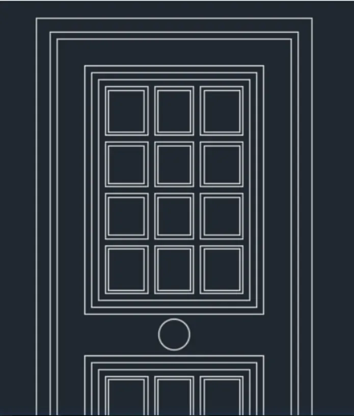
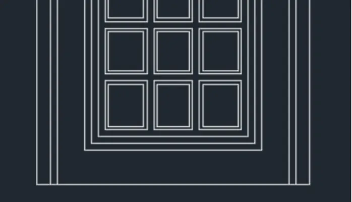
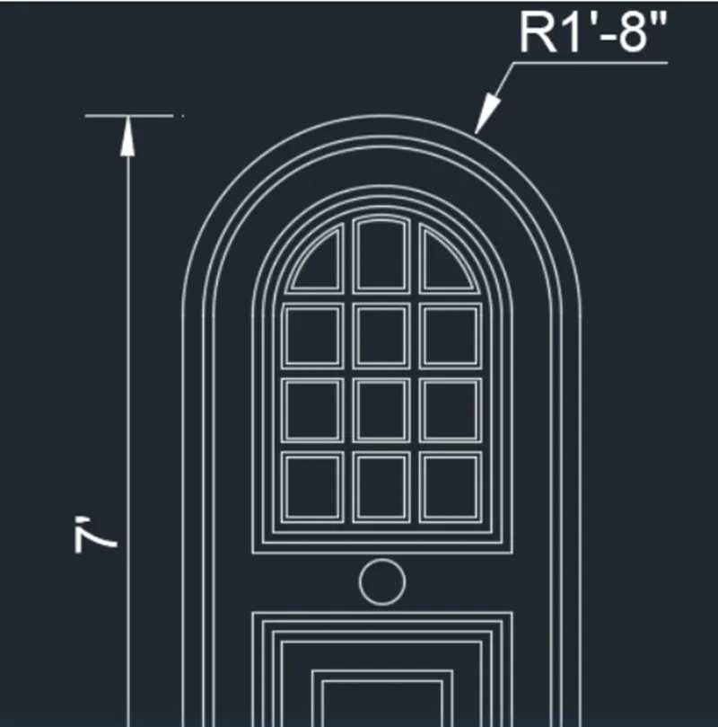
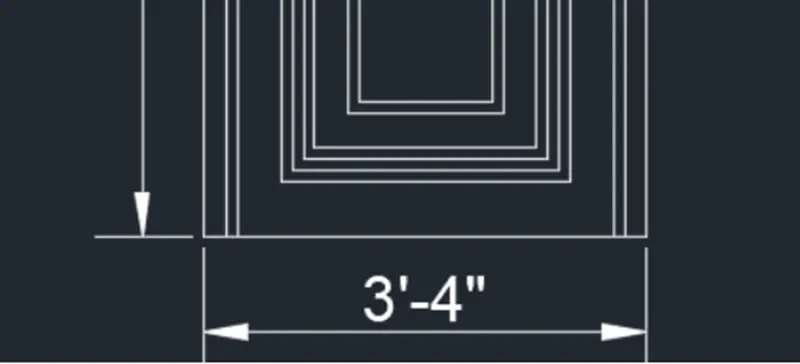
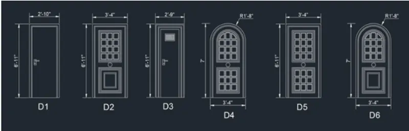
Q.4 Make the door type for residential building as a block. Save the name of the blocks as type. Utilize given dimensions or supposed dimensions as per industry standards.
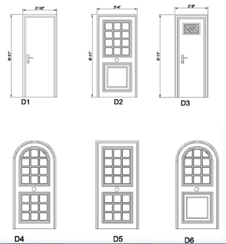
AIM: To make the door type for residential building and to save the name of the blocks as type.
INTRODUCTION:
- Doors are sketch in plan view as a heavy line in small-scale sketching’s, or as a double line, to indicate their thickness, in larger- scaled plans.
- A swing door has a thinner curved line sketch to denote the direction of its swing.
- The sketching’s of doors are sketch by the architects in the construction projects.
COMMAND UTILIZED:
- Limits command
- Single Text command
- Line command
- Dimlinear command
- Trim command
- Object snap command
- Offset command
- Units command
- Dimstyle command
- Extend command
- Block command
PROCEDURE-
STEP-1
- Go to START MENU, choose AutoCAD 2022.
- In the Command line type in: STARTUP [ENTER]
- Enter new value of startup: 1
- Go to Application Menu and choose New
- In the 'Make New Sketching dialog box, choose 'Imperial' setting.
- In the Advanced Setup and choose the Architectural' unit of measurement and choose precision as '0'-0":
- Set the limits by entering LIMITS in the Command tab. The lower-left corner is specified as O'0", 0’0"; and the upper-right corner is specified as 1000, 1000’.
- Enter 'UNITS' command in the command tab.
- In the Sketching Units dialog box, choose 'Architectural' in Type; ' 0'-0" ' in Precision; and 'Inches' in Insertion scale.
- Click on 'OK.
STEP-2
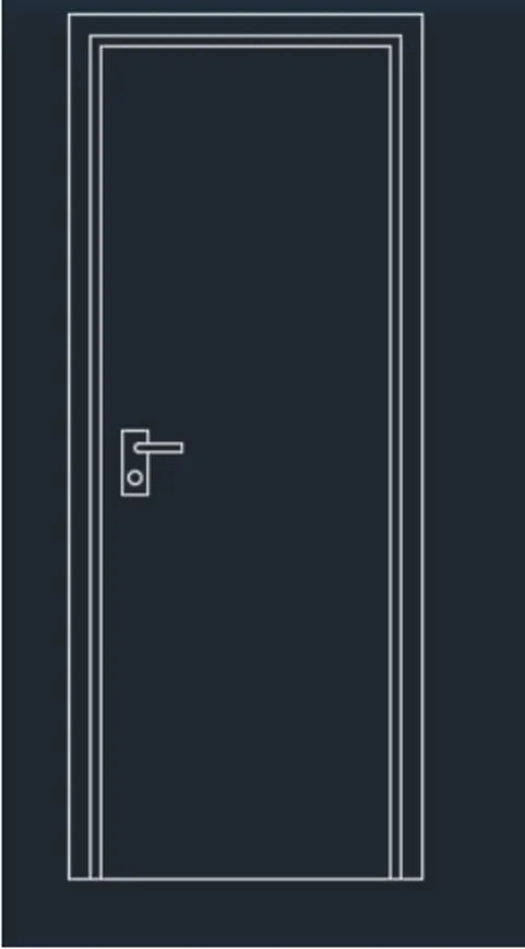
- Choose the Rectangle tool by entering 'REC command in the command tab.
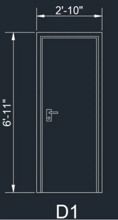
- Define the start point, Enter @2'10", 6’11".
- Thumb Esc.
- Enter X in the command tab.
- Choose the rectangle made and explode it.
- Choose the Offset tool by entering 'O' in the command tab.
- Define an offset distance of 2", choose the left side of the rectangle and then click on the inside.
- Repeat offset, define distance as 1", and then offset the three sides of the smaller inner rectangle.
- Thumb Esc to cancel the OFFSET command.
- Choose the Trim tool by entering 'TR' command in the command tab.
- Thumb ENTER.
- Choose Edge option; and click on No Extend.
- Choose the not needed lines.
- Thumb 'Esc' to cancel the TRIM command.
- Choose the Line tool by entering 'LINE' command in the command tab.
- Sketch the door handle.
- Thumb Esc.
- Enter B in the command prompt.
- In the Block Definition dialogue box, type in the name of the block as D1, pick the base point as the center of the circle, choose the object made and thumb Enter.
- Click OK.
- Choose the Dimension tool by entering 'DIM' in the command line.
- Choose the first point and second point of the object to be measured, and then drag the dimension line to the wanted location. Repeat for all the objects to be measured.
- Enter ’MTEXT command in the command line.
- Define the start point of text as needed.
- Enter text height as 6".
- Click Enter and thumb Esc.
STEP-3
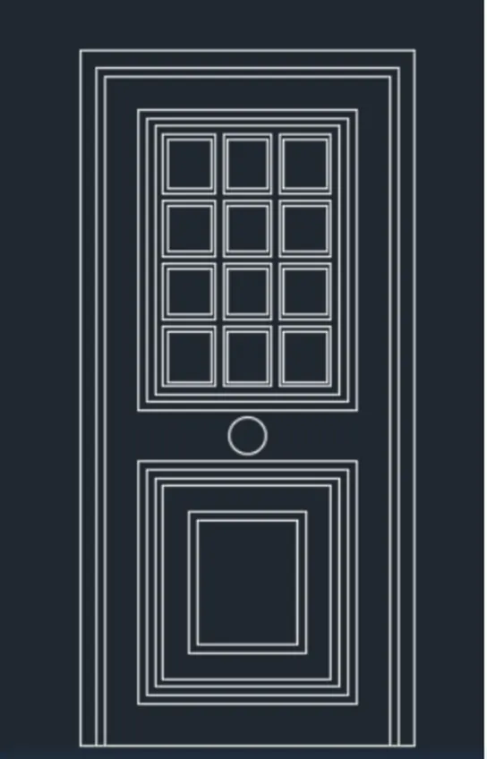
- Choose the Rectangle tool by entering 'REC command in the command tab.
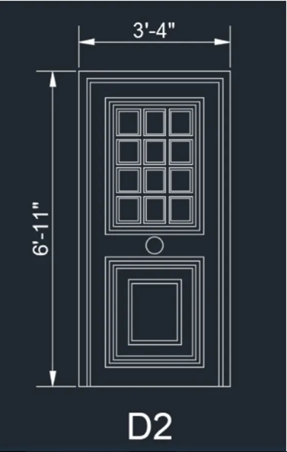
- Define the start point, Enter @3'4", 6’11".
- Thumb Esc.
- Enter X in the command tab.
- Choose the rectangle made and explode it.
- Choose the Offset tool by entering 'O' in the command tab.
- Define an offset distance of 2", choose the left side of the rectangle and then click on the inside.
- Repeat offset, define distance as 1", and then offset the three sides of the smaller inner rectangle.
- Thumb Esc to cancel the OFFSET command.
- Choose the Offset tool by entering 'O' in the command tab.
- Offset the lines to make the pattern.
- Thumb Esc.
- Choose the Trim tool by entering 'TR' command in the command tab.
- Thumb ENTER.
- Choose Edge option; and click on No Extend.
- Choose the not needed lines.
- Thumb 'Esc' to cancel the TRIM command.
- Enter B in the command prompt.
- In the Block Definition dialogue box, type in the name of the block as D2, pick the bottom right corner of the door, choose the object made and thumb Enter.
- Click OK.
- Choose the Dimension tool by entering 'DIM' in the command line.
- Choose the first point and second point of the object to be measured, and then drag the dimension line to the wanted location. Repeat for all the objects to be measured.
- Enter 'MTEXT command in the command line.
- Define the start point of text as needed.
- Enter text height as 6".
- Click Enter and thumb Esc.
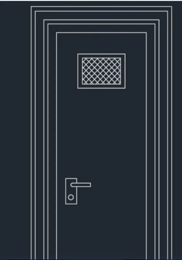
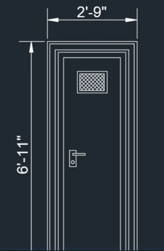
STEP-4
- Choose the Rectangle tool by entering 'REC command in the command tab.
- Define the start point, Enter @2'9", 6’11".
- Enter X in the command tab.
- Choose the rectangle made and explode it.
- Choose the Offset tool by entering 'O' in the command tab.
- Define an offset distance of 2", choose the left side of the rectangle and then click on the inside.
- Repeat offset, define distance as 1", and then offset the three sides of the smaller inner rectangle.
- Thumb Esc to cancel the OFFSET command.
- Choose the Rectangle tool by entering 'REC command in the command tab.
- Define the start point, Enter @11", 8".
- Enter H, choose ANS137, and pick point inside the rectangle.
- Thumb Esc.
- Choose the Trim tool by entering 'TR' command in the command tab.
- Thumb ENTER.
- Choose Edge option; and click on No Extend.
- Choose the not needed lines.
- Thumb 'Esc' to cancel the TRIM command.
- Choose the Line tool by entering "LINE' command in the command tab.
- Sketch the door handle.
- Thumb Esc.
- Enter B in the command prompt.
- In the Block Definition dialogue box, type in the name of the block as D3, pick the bottom right corner of the door, choose the object made and thumb Enter.
- Choose the Dimension tool by entering 'DIM' in the command line.
- Choose the first point and second point of the object to be measured, and then drag the dimension line to the wanted location. Repeat for all the objects to be measured.
- Enter 'MTEXT command in the command line.
- Define the start point of text as needed.
- Enter text height as 6".
- Click Enter and thumb Esc.
STEP-5
- Choose the Rectangle tool by entering 'REC command in the command tab.
- Define the start point; enter @3’4”7.
- Enter X in the command tab.
- Choose the rectangle made and explode it.
- Choose the Offset tool by entering 'O' in the command tab.
- Define an offset distance of 2", choose the left side of the rectangle and then click on the inside.
- Repeat offset, define distance as 1", and then offset the three sides of the smaller inner rectangle.
- Thumb Esc to cancel the OFFSET command.
- Choose the Offset tool by entering 'O' in the command tab.
- Offset the lines to make the pattern.
- Thumb Esc.
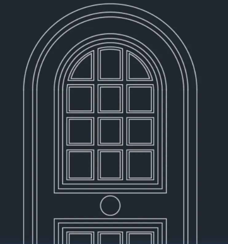
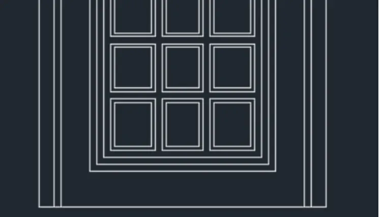
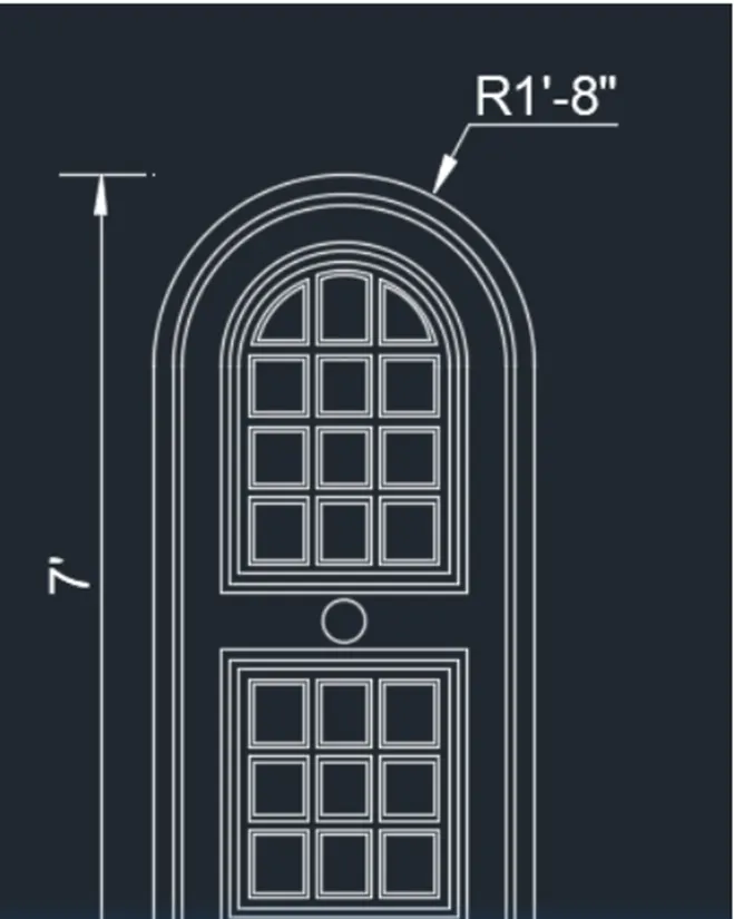
- Choose the Arc tool from the Ribbon, choose the Start, End and Direction option and sketch an arc at the top of the door.
- Choose the Offset tool by entering 'O' in the command tab.
- Define an offset distance of 2", and offset the arc multiple times.
- Thumb Esc.
- Choose the Trim tool by entering 'TR' command in the command tab.
- Thumb ENTER.
- Choose Edge option; and click on No Extend.
- Choose the not needed lines.
- Thumb 'Esc' to cancel the TRIM command.
- Choose the Line tool by entering 'LINE' command in the command tab.
- Sketch the door handle.
- Thumb Esc.
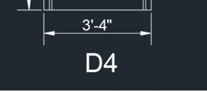
- Enter B in the command prompt.
- In the Block Definition dialogue box, type in the name of the block as D4, pick the base point as the center of the circle, choose the object made and thumb Enter.
- Click OK.
- Choose the Dimension tool by entering 'DIM' in the command line.
- Choose the first point and second point of the object to be measured, and then drag the dimension line to the wanted location. Repeat for all the objects to be measured.
- Enter 'MTEXT' command in the command line.
- Define the start point of text as needed.
- Enter text height as 6".
- Click Enter and thumb Esc.
STEP-6
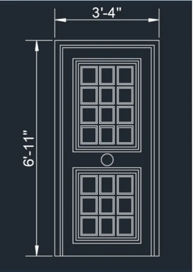
- Choose the Rectangle tool by entering REC command in the command tab.
- Define the start point. Enter @3'4", 6’11".
- Enter X in the command tab.
- Choose the rectangle made and explode it.
- Choose the Offset tool by entering 'O' in the command tab.
- Define an offset distance of 2", choose the left side of the rectangle and then click on the inside.
- Repeat offset, define distance as 1", and then offset the three sides of the smaller inner rectangle.
- Thumb Esc to cancel the OFFSET command.
- Choose the Offset tool by entering 'O' in the command tab.
- Offset the lines to make the pattern.
- Thumb Esc.
- Choose the Trim tool by entering 'TR' command in the command tab.
- Thumb ENTER.
- Choose Edge option; and click on No Extend.
- Choose the not needed lines.
- Thumb 'Esc' to cancel the TRIM command.
- Choose the Line tool by entering 'LINE' command in the command tab.
- Sketch the door handle.
- Thumb Esc.
- Enter B in the command prompt.
- In the Block Definition dialogue box, type in the name of the block as D5, pick the base point as the center of the circle, choose the object made and thumb Enter.
- Choose the Dimension tool by entering 'DIM' in the command line.
- Choose the first point and second point of the object to be measured, and then drag the dimension line to the wanted location. Repeat for all the objects to be measured.
- Enter 'MTEXT' command in the command line. Define the start point of text as needed.
- Enter text height as 6".
- Click Enter and thumb Esc.
STEP-7
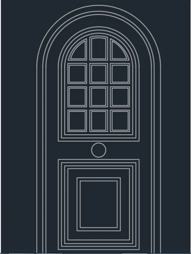
- Choose the Rectangle tool by entering 'REC command in the command tab.
- Define the start point; enter @3'4", 7.
- Enter X in the command tab.
- Choose the rectangle made and explode it.
- Choose the Offset tool by entering 'O' in the command tab.
- Define an offset distance of 2", choose the left side of the rectangle and then click on the inside.
- Repeat offset, define distance as 1", and then offset the three sides of the smaller inner rectangle.
- Thumb Esc to cancel the OFFSET command.
- Choose the Offset tool by entering 'O' in the command tab.
- Offset the lines to make the pattern.
- Thumb Esc.
- Choose the Arc tool from the Ribbon, choose the Start. End and Direction option and sketch an arc at the top of the door.
- Choose the Offset tool by entering 'O' in the command tab.
- Define an offset distance of 2", and offset the arc multiple times.
- Thumb Esc.
- Choose the Trim tool by entering 'TR' command in the command tab.
- Thumb ENTER.
- Choose Edge option; and click on No Extend.
- Choose the not needed lines.
- Thumb 'Esc' to cancel the TRIM command.
- Choose the Line tool by entering 'LINE' command in the command tab.
- Sketch the door handle.
- Thumb Esc.
- Enter B in the command prompt.
- In the Block Definition dialogue box, type in the name of the block as D5, pick the base point as the center of the circle, choose the object made and thumb Enter.
- Choose the Dimension tool by entering 'DIM' in the command line.
- Choose the first point and second point of the object to be measured, then drag the dimension line to the wanted location. Repeat for all the objects to be measured.
- Enter 'MTEXT' command in the command line.
- Define the start point of text as needed.
- Enter text height as 6".
- Click Enter and thumb Esc.
RESULT-
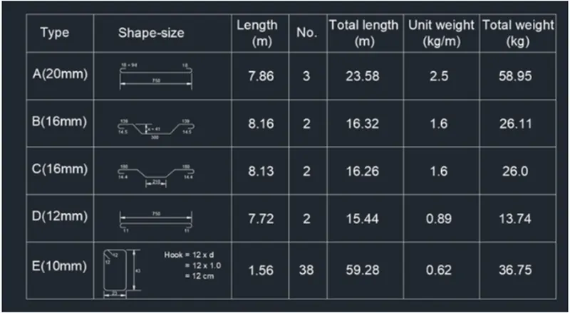
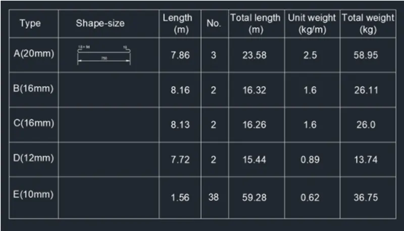
Q.5 Make each shape as a block as given in the Picture. Save the block and insert them on the table as given in the Picture.
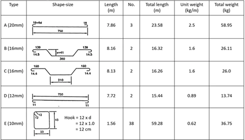
AIM- To make the bar shape as block with the name and to make the blocks and arrange them in the table.
INTRODUCTION-
- Bar Bending Schedule is a definitive list of reinforcement bars for any structural element that includes a mark, shape, size, location, length, and bending details of the reinforcement.
- It is often referred to as BBS.
- Tabular view representation of each reinforcement bar utilized in any structural element is known as BBS.
COMMAND UTILIZED-
- Limits command
- Single Text command
- Line command
- Dimlinear command
- Trim command
- Object snap command
- Offset command
- Units command
- Dimstyle command
- Extend command
- Block command
- LW command
- LT command
PROCEDURE-
STEP-1
- Go to START MENU, choose AutoCAD 2022.
- In the Command line type in: STARTUP [ENTER]
- Enter 'UNITS' command in the command tab.
- In the Sketching Units dialog box, choose 'Decimal' in Type: ' 0.00' in Precision; and 'Millimeters' in Insertion scale.
- Click on 'OK'.
- Set the limits by entering LIMITS in the Command tab. The lower-left corner is specified as 0, 0; and the upper-right corner is specified as 10000, 10000.
STEP-2
- Choose the Line tool by entering LINE' command in the command tab.
- Sketch a line of length 750.
- Thumb Esc.
- Choose the Arc tool from the Ribbon, choose the Start, End and Direction option and sketch an arc on both ends of the line.
- Choose the Dimension tool by entering 'DIM' in the command line.
- Choose the first point and second point of the object to be measured, and then drag the dimension line to the wanted location.
- Repeat for all the objects to be measured.
- Enter 'MTEXT' command in the command line.
- Define the start point of text as needed.
- Enter text height as 40.
- Click Enter and thumb Esc.
- Copy the text box to wherever necessary.
- Enter ED in the command prompt and edit the text boxes as needed.
- Click Enter and thumb Esc.
- Enter B in the command prompt.
- In the Block Definition dialogue box, type in the name of the block as A (20mm), pick the bottom right corner of the door. Choose the object made and thumbes Enter.
- Click

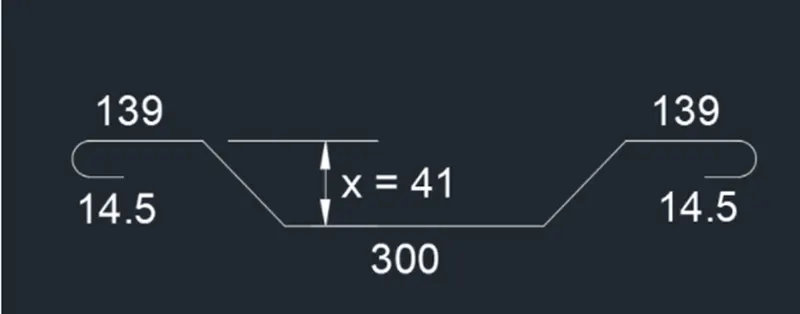
STEP-3
- Choose the Line tool by entering LINE' command in the command tab.
- Sketch a line of length 300.
- Thumb Esc.
- Choose the Arc tool from the Ribbon, choose the Start, End and Direction option and sketch an arc on both ends of the line.
- Choose the LINE tool by entering 'LINE' in the command line.
- Sketch inclined lines depicting the bending in the bar.
- Thumb Esc.
- Choose the Dimension tool by entering 'DIM' in the command line.
- Choose the first point and second point of the object to be measured, and then drag the dimension line to the wanted location.
- Repeat for all the objects to be measured.
- Enter 'MTEXT' command in the command line.
- Define the start point of text as needed.
- Enter text height as 40.
- Click Enter and thumb Esc.
- Copy the text box to wherever necessary.
- Enter ED in the command prompt and edit the text boxes as needed.
- Click Enter and thumb Esc.
- Enter B in the command prompt.
- In the Block Definition dialogue box, type in the name of the block as B (16mm), pick the bottom right corner of the door. Choose the object made and thumbs Enter.
- Click
STEP-4
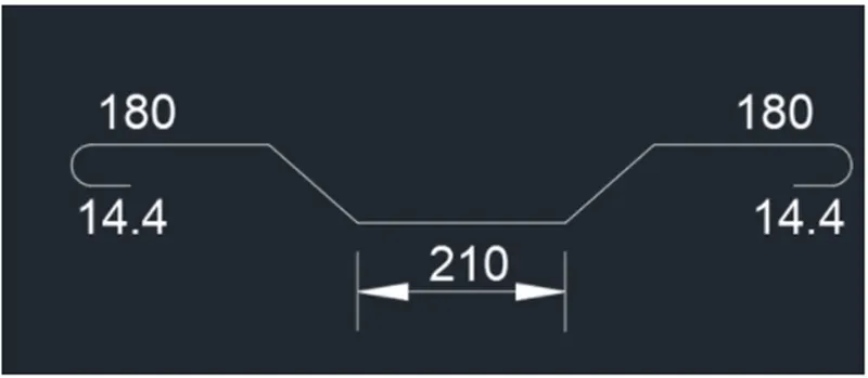
- Choose the Line tool by entering LINE' command in the command tab.
- Sketch a line of length 210.
- Thumb Esc.
- Choose the Line tool by entering LINE' command in the command tab.
- Sketch inclined lines depicting the bending in the bar.
- Thumb Esc.
- Choose the Arc tool from the Ribbon, choose the Start, End and Direction option and sketch an arc on both ends of the line.
- Choose the Line tool by entering LINE' command in the command tab.
- Sketch inclined lines depicting the bending in the bar.
- Thumb Esc.
- Choose the Dimension tool by entering 'DIM' in the command line.
- Choose the first point and second point of the object to be measured, and then drag the dimension line to the wanted location.
- Repeat for all the objects to be measured.
- Enter 'MTEXT' command in the command
- Define the start point of text as needed.
- Enter text height as 40.
- Click Enter and thumb Esc.
- Copy the text box to wherever necessary.
- Enter ED in the command prompt and edit the text boxes as needed.
- Click Enter and thumb Esc.
- Enter B in the command prompt.
- In the Block Definition dialogue box, type in the name of the block as C (16mm), pick the bottom right corner of the door. Choose the object made and thumbs Enter.
- Click
STEP-5
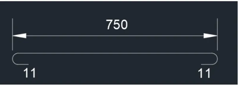
- Choose the Line tool by entering 'LINE' command in the command tab.
- Sketch a line of length 750.
- Thumb Esc.
- Choose the Arc tool from the Ribbon, choose the Start, End and Direction option and sketch an arc on both ends of the line.
- Choose the Line tool by entering 'LINE' command in the command tab.
- Sketch lines of length 11 from the arcs.
- Thumb Esc.
- Choose the Dimension tool by entering 'DIM' in the command line.
- Repeat for all the objects to be measured.
- Enter 'MTEXT' command in the command line.
- Define the start point of text as needed.
- Enter text height as 40.
- Click Enter and thumb Esc.
- Copy the text box to wherever necessary.
- Enter ED in the command prompt and edit the text boxes as needed.
- Click Enter and thumb Esc.
- Enter B in the command prompt.
- In the Block Definition dialogue box, type in the name of the block as D (12mm), pick the bottom right corner of the door. Choose the object made and thumbes Enter.
- Click
STEP-6
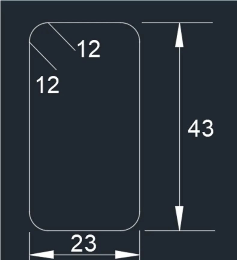
- Choose the Rectangle tool by entering 'REC command in the command tab.
- Define the start point; enter @230,430.
- Enter X in the command tab.
- Choose the rectangle made and explode it.
- Enter F in the command prompt.
- Define radius as 20.
- Fillet the corners of the rectangle.
- Thumb Esc.
- Choose the Line tool by entering 'LINE' command in the command tab.
- Sketch hooks lines of length 12 cm.
- Thumb Esc.
- Choose the Dimension tool by entering 'DIM' in the command line.
- Choose the first point and second point of the object to be measured, and then drag the dimension line to the wanted location.
- Repeat for all the objects to be measured.
- Enter 'MTEXT' command in the command line.
- Define the start point of text as needed.
- Enter text height as 40.
- Click Enter and thumb Esc.
- Copy the text box to wherever necessary.
- Enter ED in the command prompt and edit the text boxes as needed.
- Click Enter and thumb Esc.
- Enter B in the command prompt.
- In the Block Definition dialogue box, type in the name of the block as E (10mm), pick the bottom right corner of the door. Choose the object made and thumbes Enter.
- Click
STEP-7
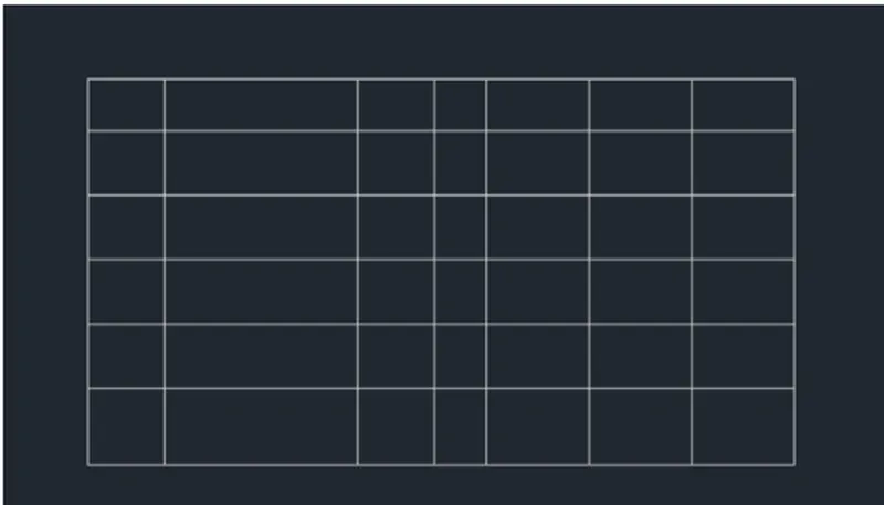
- Choose the Rectangle tool by entering 'REC command in the command tab.
- Define the start point; enter @5500, 3000.
- Thumb Esc.
- Enter X in the command tab.
- Choose the rectangle made and explode it.
- Choose the Offset tool by entering 'O' in the command tab.
- Choose an offset distance of 400, choose top line and offset it.
- Repeat Offset, define distance as 500, and choose the previous offsetted line and offset it 4 times.
- Thumb Esc to cancel the OFFSET command.
- Choose the Offset tool by entering 'O' in the command tab.
- Define an offset distance of 700, choose left hand line and offset it.
- Repeat Offset, define distance as 1400, and choose the previous offsetted line and offset it.
- Repeat Offset, define distance as 600, and choose the previous offsetted line and offset it.
- Repeat Offset, define distance as 400, and choose the previous offsetted line and offset it.
- Repeat Offset, define distance as 600, and choose the previous offsetted line and offset it twice.
- Thumb Esc to cancel the OFFSET command.
- Choose the Trim tool by entering 'TR' command in the command tab.
- Thumb ENTER.
- Choose Edge option; and click on No Extend.
- Choose the not needed lines.
- Thumb 'Esc' to cancel the TRIM command.
STEP-8
- Enter 'MTEXT' command in the command line.
- Define the start point of text as needed.
- Enter text height as 150.
- Click Enter and thumb Esc.
- Copy the text box to wherever necessary.
- Enter ED in the command prompt and edit the text boxes as needed.
- Click Enter and thumb Esc.
- Save the sketching.
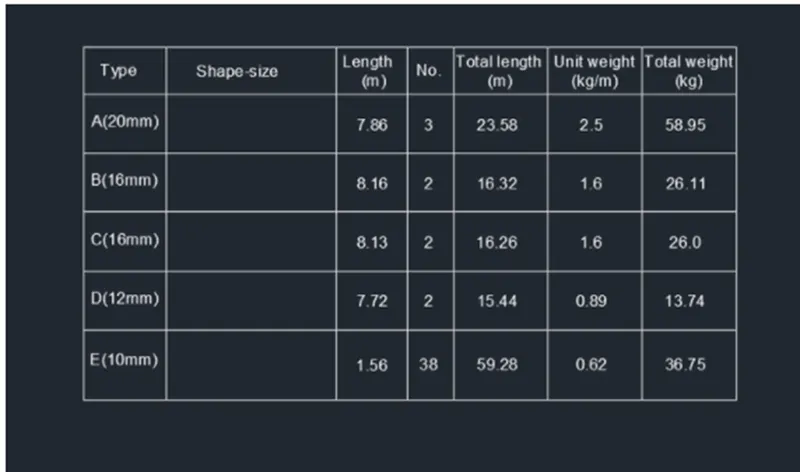
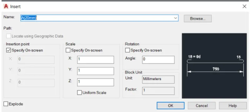
- Enter i command in the command prompt.
- In the insert dialog box, choose the symbols made in step 2-6, click OK and insert them into the bar bending schedule table one by one.
- Save the sketching.
RESULT-