Creating Bar Bending schedule, Different Door types, and Creation of standard drawing templates using AutoCad
1. Create the templates as shown in Figures. Take the size of the title block as per industry standards or you can assume it as per the size of the paper. Use text and attributes wherever required. After creating the title block you need to save it as a block with names: Custom1_titleblock and Custom2_titleblock, respectively.
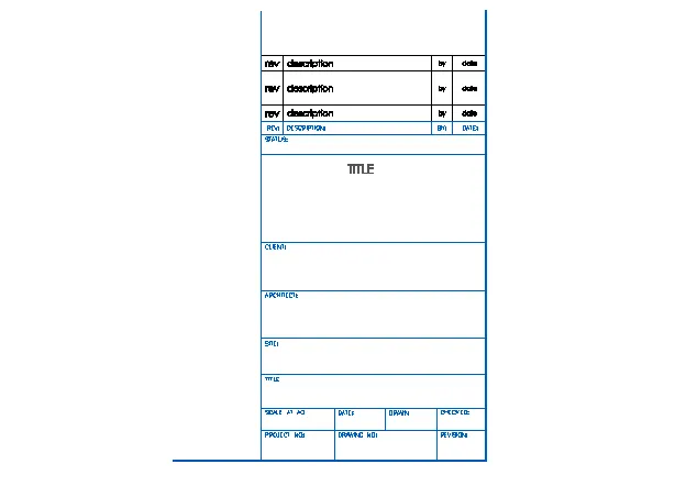
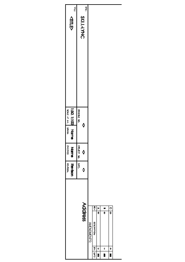
Answer:-
step1:- command a xl line and draw vertical line and again command xl line and draw a horizontal line, the two are trim negative directions and use offset with above daigram have dimensions and draw a residential plan.
step2:- command a circle tool used the door shape.
step3:- command a dimlinear and show the dimensions.
step4:- select the separted parts like walls (exterior, interior), doors , caboards, steps, are select individual and apply a different colour for each item.
step5:- command a table tool and select no rows and columns and draw a table.
step6:- command a line tool and draw a reinforcement.
step7:- command a text and enter all the text and save.
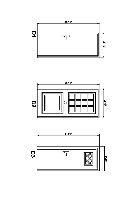
2. Create the doors type for warehouse as shown in the Figure. You need to create each door type as per standard size or given dimensions. Create the blocks of this door type after creating them.
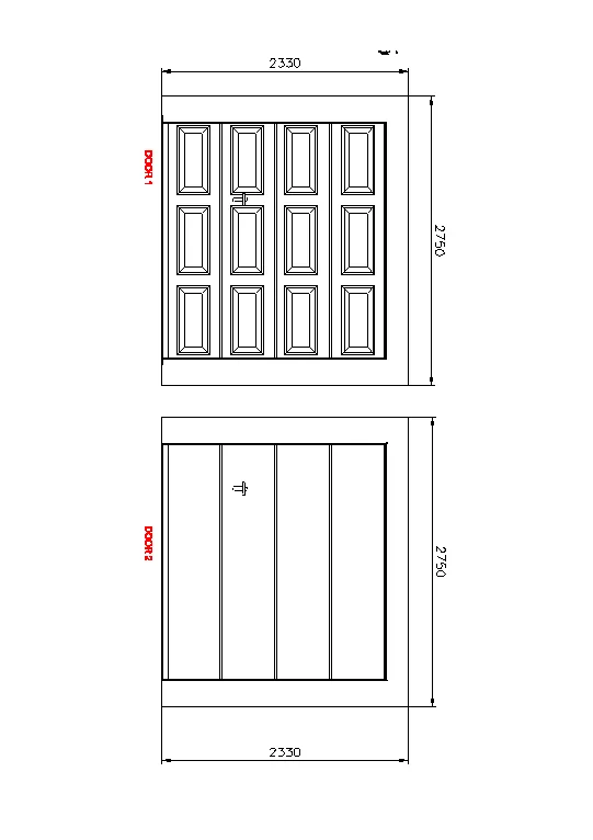
Answer:-
step1:- command a xl line and draw vertical line and again command xl line and draw a horizontal line, the two are trim negative directions and use offset with above daigram have dimensions and draw a residential plan.
step2:- command a circle tool used the door shape.
step3:- command a dimlinear and show the dimensions.
step4:- select the separted parts like walls (exterior, interior), doors , caboards, steps, are select individual and apply a different colour for each item.
step5:- command a table tool and select no rows and columns and draw a table.
step6:- command a line tool and draw a reinforcement.
step7:- command a text and enter all the text and save.
3. Create each symbol as a block with the name given in the legend. After creating the blocks arrange them in the legend as shown in the Figure.
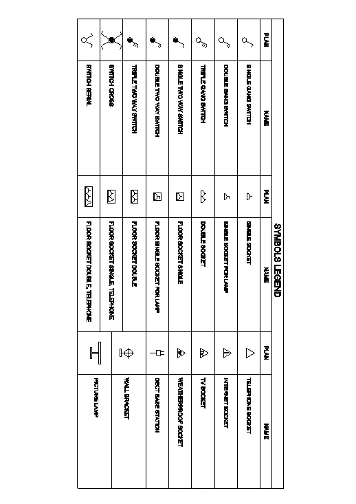
Answer:-
step1:- command a xl line and draw vertical line and again command xl line and draw a horizontal line, the two are trim negative directions and use offset with above daigram have dimensions and draw a residential plan.
step2:- command a circle tool used the door shape.
step3:- command a dimlinear and show the dimensions.
step4:- select the separted parts like walls (exterior, interior), doors , caboards, steps, are select individual and apply a different colour for each item.
step5:- command a table tool and select no rows and columns and draw a table.
step6:- command a line tool and draw a reinforcement.
step7:- command a text and enter all the text and save.
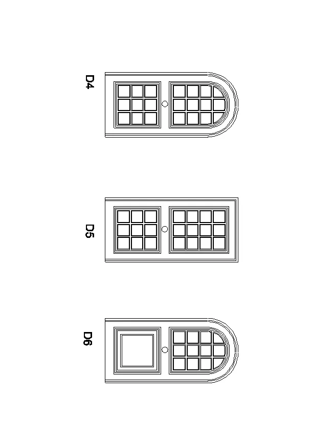
4. Create the door type for residential building as a block. Save the name of the blocks as type. Use given dimensions or assume dimensions as per industry standards.
Answer:-
step1:- command a xl line and draw vertical line and again command xl line and draw a horizontal line, the two are trim negative directions and use offset with above daigram have dimensions and draw a residential plan.
step2:- command a circle tool used the door shape.
step3:- command a dimlinear and show the dimensions.
step4:- select the separted parts like walls (exterior, interior), doors , caboards, steps, are select individual and apply a different colour for each item.
step5:- command a table tool and select no rows and columns and draw a table.
step6:- command a line tool and draw a reinforcement.
step7:- command a text and enter all the text and save.
5. Create each shape as a block as shown in the Figure. Save the block and insert them on the table as shown in the Figure.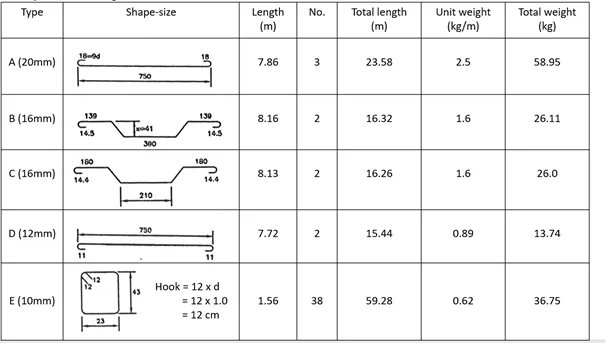
Answer:-
step1:- command a xl line and draw vertical line and again command xl line and draw a horizontal line, the two are trim negative directions and use offset with above daigram have dimensions and draw a residential plan.
step2:- command a circle tool used the door shape.
step3:- command a dimlinear and show the dimensions.
step4:- select the separted parts like walls (exterior, interior), doors , caboards, steps, are select individual and apply a different colour for each item.
step5:- command a table tool and select no rows and columns and draw a table.
step6:- command a line tool and draw a reinforcement.
step7:- command a text and enter all the text and save.