Creating Bar Bending schedule, Different Door types, and Creation of standard drawing templates using AutoCad
|
Creating Bar Bending schedule, Different Door types, and Creation of standard drawing templates using AutoCad |
PROBLEM 1
- Aim :- To create the templates and save the templates as a block.
- Introduction :-
The general commands used for drawing the building is as follows :
- Line
- Polygon
- Rectangle
- Circle
- Erase
- Copy
- Trim
- Mirror
- Offset
- Extend
- Array
- Move
- Rotate
- Dimension
- Text
- Fillet
Etc.
- Procedure :-
1. To Create Template 1 :
- Click on AutoCAD application and open this application
- Type QNEW in command bar and enter
- Select default setting as Metric
- In default setting click on use a wizard and in that advance setting and set unit as decimal and precision as 0 and press Next
- Set Angle as Decimal Degree and precision as 0 and click next
- Set Angle Measure as EAST and press NEXT
- Set Angle Direction as Counter-Clockwise and press NEXT
- Set Area by providing Length as 50 and Width as 50
- Press finish
- Keep ortho, Object snap >ON
- Keep Snap and Grid > Off
- Un+enter
- Type > Decimal, Precision > 0
- Units to scale inserted content > milimeter
- Enter
- Click on layer properties
- Click on new layer
- Give the layer name > Template Table
- Turn the layer ON
- Set Unlock
- Slect layer colour > Green
- Click on new layer
- Give the layer name > Text
- Turn the layer ON
- Set Unlock
- Slect layer colour > Cyan
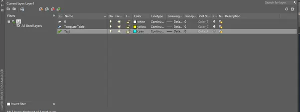
- The layers which are assigned are shown in below fig
- Set the current layer as Template Table
- Take a line command
- Specify first point > Anywhere in the drawing
- Specify next point > 300 > keeping the curser right side > enter
- Specify next point > 250 > keeping the curser upside > enter
- Take offset command
- Specify offset distance > 30
- Specfy object > Click on the horizontal line and take curser upside
- Specify offset distance > 20 > Enter
- Specify object as > Click on the last offset created line and take curser upside
- Specify offset distance > 35> Enter
- Specify object as > Click on the last offset created line and take curser upside
- Specify offset distance > 35 > Enter
- Specify object as > Click on the last offset created line and take curser upside
- Specify offset distance > 40 > Enter
- Specify object as > Click on the last offset created line and take curser upside
- Specify offset distance > 80 > Enter
- Specify object as > Click on the last offset created line and take curser upside
- Specify offset distance > 30 > Enter
- Specify object as > Click on the last offset created line and take curser upside
- Specify offset distance > 20 > Enter
- Specify object as > Click on the last offset created line and take curser upside
- Specify offset distance > 30 > Enter
- Specify object as > Click on the last offset created line and take curser upside
- Specify offset distance > 40 > Enter
- Specify object as > Click on the last offset created line and take curser upside
- Specify offset distance > 30 > Enter
- Specify object as > Click on the last offset created line and take curser upside
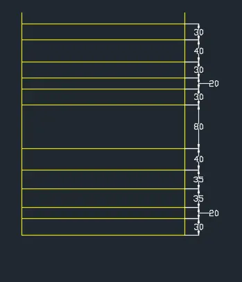
- It will gives you result as shown below
- Take offset command
- Specify offset distance > 60
- Specfy object > Click on the Right side vertical line and take curser Left side
- Specify offset distance > 20 > Enter
- Specify object as > Click on the last offset created line and take curser Left side
- Specify offset distance > 10 > Enter
- Specify object as > Click on the last offset created line and take curser Left side
- Specify offset distance > 50 > Enter
- Specify object as > Click on the last offset created line and take curser Left side
- Specify offset distance > 60 > Enter
- Specify object as > Click on the last offset created line and take curser Left side
- Specify offset distance > 50 > Enter
- Specify object as > Click on the last offset created line and take curser Left side
- Trim and erase the unwanted parts to create the table
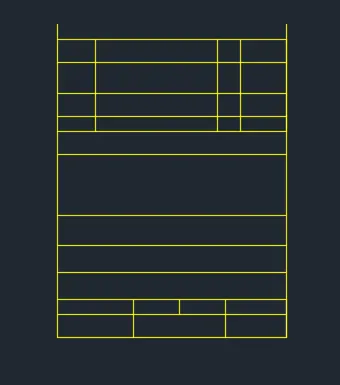
- The table is ready as shown below
- Change the current layer to text layer
- To create the text
- Click on Annotation tab >multi line
- Manage textile > New
- Style name as > Template 1 > OK
- Font Name > Arial
- Height > 7
- And press set current
- Use multiline text
- And fill the required text at required position
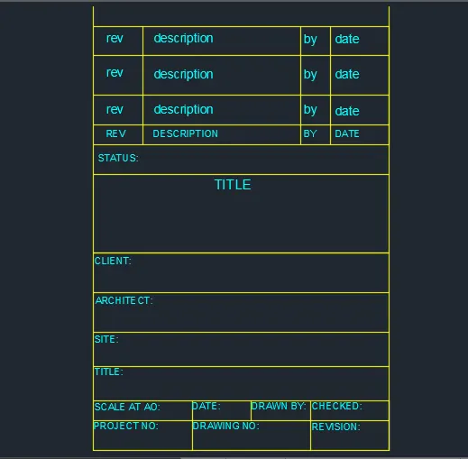
- The texts are as follows
- rev
- description
- by
- date
- REV
- DESCRIPTION
- BY
- DATE
- STATUS
- TITLE
- CLIENT
- ARCHITECT
- SITE
- TITLE etc.
- All the text can be placed in a proper position by using move command
- Select the title text and increase its size to 10
- The Template is ready as shown below
- Take block command by
- type B > enter
- dialogue box will be open
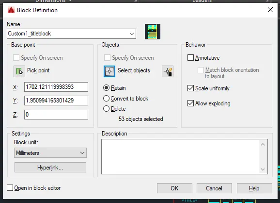
- Name > Custom1_titleblock
- Click on > Pick point
- Block specify insertion base point > click on any one corner of the table
- Select object > take a cross window and select whole template
- Block select object > enter
- Click on > Retain
- Scale uniformly > Mark it by clicking through curser
- Allow exploding > Mark it by clicking through curser as shown below
- Click on > Ok
- Enter
- The template is saved as a block
2. To Create Template 2 :
- Click on AutoCAD application and open this application
- Type QNEW in command bar and enter
- Select default setting as Metric
- In default setting click on use a wizard and in that advance setting and set unit as decimal and precision as 0 and press Next
- Set Angle as Decimal Degree and precision as 0 and click next
- Set Angle Measure as EAST and press NEXT
- Set Angle Direction as Counter-Clockwise and press NEXT
- Set Area by providing Length as 50 and Width as 50
- Press finish
- Keep ortho, Object snap >ON
- Keep Snap and Grid > Off
- Un+enter
- Type > Decimal, Precision > 0
- Units to scale inserted content > milimeter
- Enter
- Click on layer properties
- Click on new layer
- Give the layer name > Template Table
- Turn the layer ON
- Set Unlock
- Slect layer colour > Green
- Click on new layer
- Give the layer name > Text
- Turn the layer ON
- Set Unlock
- Slect layer colour > Cyan
- Click on new layer
- Give the layer name > Outline
- Turn the layer ON
- Set Unlock
- Slect layer colour > Red
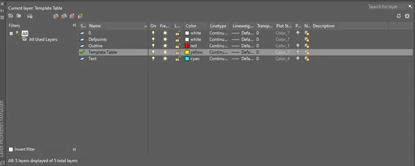
- The layers which are assigned are shown in below fig
- Set the current layer as outline layer
- Take a line command
- Specify first point > Anywhere in the drawing
- Specify next point > 1000 > keeping the curser right side > enter
- Specify next point > 300 > keeping the curser upside > enter
- Take offset command
- Specify offset distance > 75
- Specfy object > Click on the horizontal line and take curser upside
- Specify offset distance > 75 > Enter
- Specify object as > Click on the last offset created line and take curser upside
- Specify offset distance > 30> Enter
- Specify object as > Click on the last offset created line and take curser upside
- Specify offset distance > 30 > Enter
- Specify object as > Click on the last offset created line and take curser upside
- Specify offset distance > 50 > Enter
- Specify object as > Click on the last offset created line and take curser upside
- Specify offset distance > 30 > Enter
- Specify object as > Click on the last offset created line and take curser upside
- Take all these objects to the template table layer
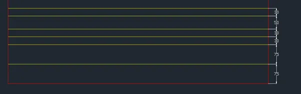
- It will gives you result as shown below
- Take offset command
- Specify offset distance > 60
- Specfy object > Click on the Right side vertical line and take curser Left side
- Specify offset distance > 40 > Enter
- Specify object as > Click on the last offset created line and take curser Left side
- Specify offset distance > 200 > Enter
- Specify object as > Click on the last offset created line and take curser Left side
- Specify offset distance > 50 > Enter
- Specify object as > Click on the last offset created line and take curser Left side
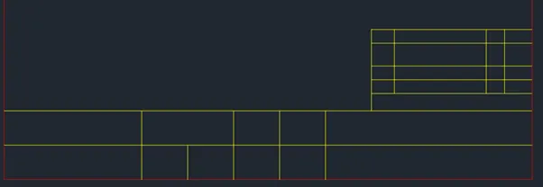
- Similarly take offset command and prepare the table as per requirement
- Trim and erase the unwanted parts to create the table
- The table is ready as shown below
- Change the current layer to text layer
- To create the text
- Click on Annotation tab >multi line
- Manage textile > New
- Style name as > Template 2 > OK
- Font Name > Arial
- Height > 10
- And press set current
- Use multiline text
- And fill the required text at required position
- The texts are as follows
- REV
- DESCRIPTION
- BY
- DATE etc.
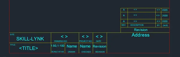
- All the text can be placed in a proper position by using move command
- As per requirement text height can be increased as shown below
- The Template is ready as shown below
- Take block command by
- type B > enter
- dialogue box will be open
- Name > Custom2_titleblock
- Click on > Pick point
- Block specify insertion base point > click on any one corner of the table
- Select object > take a cross window and select whole template
- Block select object > enter
- Click on > Retain
- Scale uniformly > Mark it by clicking through curser
- Allow exploding > Mark it by clicking through curser as shown below
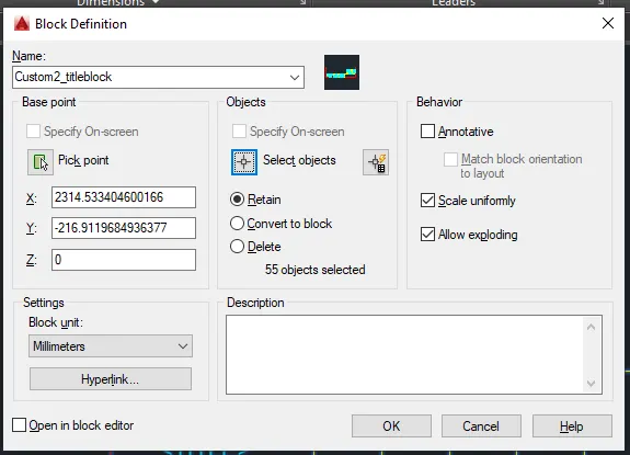
- Click on > Ok
- Enter
- The template is saved as a block
- RESULT :-
- TTEMPLATE 1
- TEMPLATE 2
PROBLEM 2
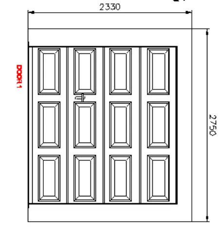
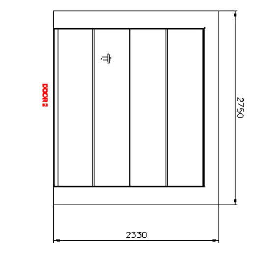
- Aim :- To create the Door1 and Door2 as shown below and save the respective door as a block.
- Introduction :-
The general commands used for drawing the building is as follows :
- Line
- Polygon
- Rectangle
- Circle
- Erase
- Copy
- Trim
- Mirror
- Offset
- Extend
- Array
Etc.
- Procedure :-
1. To Create Door 1 :
- Click on AutoCAD application and open this application
- Type QNEW in command bar and enter
- Select default setting as Metric
- In default setting click on use a wizard and in that advance setting and set unit as decimal and precision as 0 and press Next
- Set Angle as Decimal Degree and precision as 0 and click next
- Set Angle Measure as EAST and press NEXT
- Set Angle Direction as Counter-Clockwise and press NEXT
- Set Area by providing Length as 50 and Width as 50
- Press finish
- Keep ortho, Object snap >ON
- Keep Snap and Grid > Off
- Un+enter
- Type > Decimal, Precision > 0
- Units to scale inserted content > milimeter
- Enter
- Click on layer properties
- Click on new layer
- Give the layer name > Door frame
- Turn the layer ON
- Set Unlock
- Slect layer colour > Pink
- Click on new layer
- Give the layer name > Door Panel
- Turn the layer ON
- Set Unlock
- Slect layer colour > Green
- Give the layer name > Door
- Turn the layer ON
- Set Unlock
- Slect layer colour > Cyan
- Give the layer name > Handle
- Turn the layer ON
- Set Unlock
- Slect layer colour > Red
- Give the layer name > Door Panel
- Turn the layer ON
- Set Unlock
- Slect layer colour > Green
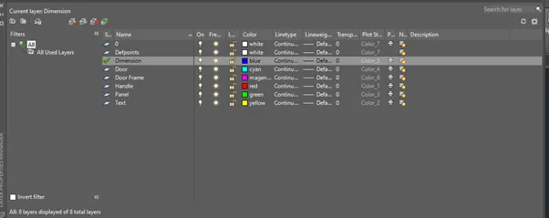
- The layers which are assigned are shown in below fig
- Set the current layer as door frame layer
- Take a line command
- Specify first point > Anywhere in the drawing
- Specify next point as > 2330 > enter by keeping curser rightside
- Specify next point as > 2750 > enter by keeping curser up side
- Specify next point as > 2330 > enter by keeping curser lrftside
- Specify next point as > 2750 > enter by keeping curser downside
- Take offset command
- Specify offset distance > 230
- Specfy object > Click on the bottom horizontal line and take curser upside
- Specify offset distance > 230
- Specfy object > Click on the top horizontal line and take curser down side
- Specify offset distance > 230
- Specfy object > Click on the upper right side vertical line and take curser left side
- Specify offset distance > 100
- Specfy object > Click on the left side vertical line and take curser upside
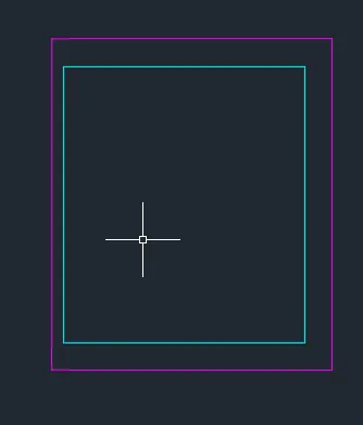
- Take all these offseted lines n the door layer
- Change current layer to door layer
- It will show us following result
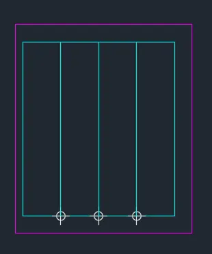
- Take divide command
- Select the object to divide > click on bottom horizontal line from the door layer
- Divide this line > 4 segment > enter
- Take the point style command
- Change the point style as to draw the line
- Take line command
- And draw the lines from all these nodes as shown below
- Again change the point style to the normal point style
- Take offset command
- Specify distance as 20
- Select object > select all these divide lines and offset these lines from both the sides
- Once againTake offset command
- Specify distance as 70
- Select object > select all these divide lines and offset these lines from both the sides

- Take divide command
- Select the object to divide > click on left side verticalline from the door layer
- Divide this line > 3 segment > enter
- Take the point style command
- Change the point style as to draw the line
- Take line command
- And draw the lines from all these nodes as shown below
- Take offset command
- Specify distance as 20
- Select object > select all these divide lines and offset these lines from both the sides
- Once againTake offset command
- Specify distance as 70
- Select object > select all these divide lines and offset these lines from both the sides
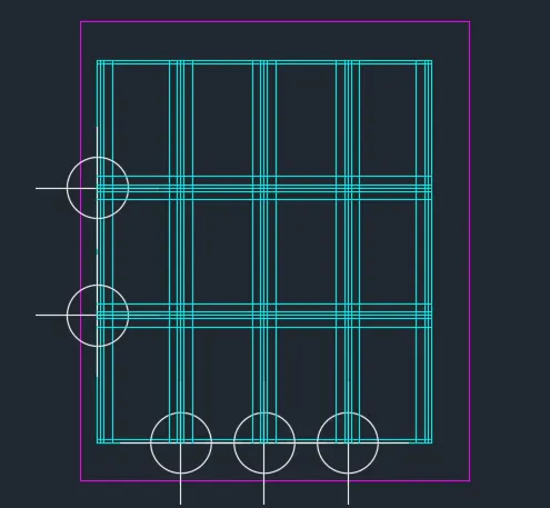
- Change the point style to normal point style
- Change the current layer to panel layer
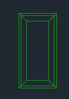
- Take rectangle command
- Specify corner point > anywhere
- Specify > dimension
- Length > 340, width > 680
- Enter
- Take offset command
- Specify distance as 20
- Select object > click on rectangle > enter keeping curser inwords
- Take offset command
- Specify distance as 50
- Select object > click on inner rectangle rectangle > enter keeping curser inwords
- Take a line command and join the corners as shown below
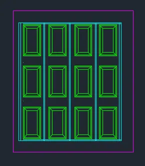
- Take the copy command
- Select object > select panel
- Specify base point > click on any corner of panel
- Place to a required positions as per drawing by keeping object snap ON
- Trim and erase all the unwanted lines as per shown below
- Change current layer to handle layer
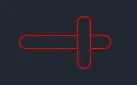
- Take rectangle command
- Specify corner point > anywhere
- Click > dimension
- Length > 300, Width > 50
- Enter
- Take rectangle command
- Specify corner point > anywhere
- Click > dimension
- Length > 50, Width > 150
- Enter
- Take fillet option
- Multiple
- Use the fillet command to provide the arc at both the ends of rectangle
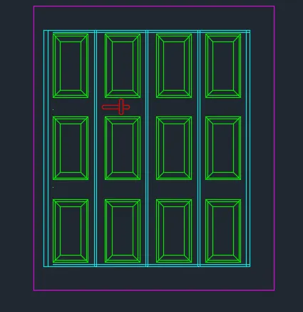
- Move the another rectangle and place in proper positon as it will show handle as shown below
- Move the whole handle such as shown below
- Change the current layer to text layer
- To create the text
- Click on Annotation tab >multi line
- Manage textile > New
- Style name as > Door 1 > OK
- Font Name > Arial
- Height > 150
- And press set current
- Use multiline text
- And fill the required text at required position
- Click on ANNOTATION tab
- Click on Dimension
- Click > Manage dimension style
- Style name > Project
- Set the characteristics of dimensions as
- Select the yellow colour for the dimension style and extension line
- Select arrowhead size as 50
- Select the text as Cyan colour
- Select Text Style > Door 1
- Then select linear dimensions
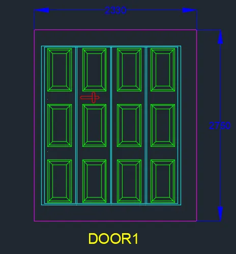
- Provide the linear dimension
- And similarly this way, provide the dimensions wherever necessary as shown below
- Take block command by
- type B > enter
- dialogue box will be open
- Name > Door 1
- Click on > Pick point
- Block specify insertion base point > click on any one corner
- Select object > take a cross window and select whole drawing
- Block select object > enter
- Click on > Retain
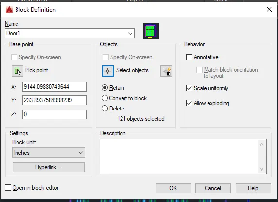
- Scale uniformly > Mark it by clicking through curser
- Allow exploding > Mark it by clicking through curser as shown below
- Click on > Ok
- Enter
- The block is ready
2. To Create Door 2 :
- Click on AutoCAD application and open this application
- Type QNEW in command bar and enter
- Select default setting as Metric
- In default setting click on use a wizard and in that advance setting and set unit as decimal and precision as 0 and press Next
- Set Angle as Decimal Degree and precision as 0 and click next
- Set Angle Measure as EAST and press NEXT
- Set Angle Direction as Counter-Clockwise and press NEXT
- Set Area by providing Length as 50 and Width as 50
- Press finish
- Keep ortho, Object snap >ON
- Keep Snap and Grid > Off
- Un+enter
- Type > Decimal, Precision > 0
- Units to scale inserted content > milimeter
- Enter
- Click on layer properties
- Click on new layer
- Give the layer name > Door frame
- Turn the layer ON
- Set Unlock
- Slect layer colour > Pink
- Click on new layer
- Give the layer name > Door Panel
- Turn the layer ON
- Set Unlock
- Slect layer colour > Green
- Give the layer name > Door
- Turn the layer ON
- Set Unlock
- Slect layer colour > Cyan
- Give the layer name > Handle
- Turn the layer ON
- Set Unlock
- Slect layer colour > Red
- Give the layer name > Door Panel
- Turn the layer ON
- Set Unlock
- Slect layer colour > Green
- The layers which are assigned are shown in below fig
- Set the current layer as door frame layer
- Take a line command
- Specify first point > Anywhere in the drawing
- Specify next point as > 2330 > enter by keeping curser rightside
- Specify next point as > 2750 > enter by keeping curser up side
- Specify next point as > 2330 > enter by keeping curser lrftside
- Specify next point as > 2750 > enter by keeping curser downside
- Take offset command
- Specify offset distance > 230
- Specfy object > Click on the bottom horizontal line and take curser upside
- Specify offset distance > 230
- Specfy object > Click on the top horizontal line and take curser down side
- Specify offset distance > 230
- Specfy object > Click on the upper right side vertical line and take curser left side
- Specify offset distance > 100
- Specfy object > Click on the left side vertical line and take curser upside
- Take all these offseted lines n the door layer
- Change current layer to door layer
- It will show us following result
- Take divide command
- Select the object to divide > click on bottom horizontal line from the door layer
- Divide this line > 4 segment > enter
- Take the point style command
- Change the point style as to draw the line
- Take line command
- And draw the lines from all these nodes as shown below
- Again change the point style to the normal point style
- Take offset command
- Specify distance as 20
- Select object > select all these divide lines and offset these lines from both the sides
- Once againTake offset command
- Specify distance as 70
- Select object > select all these divide lines and offset these lines from both the sides
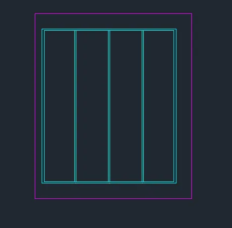
- Trim and erase all the unwanted lines as per shown below
- Change current layer to handle layer
- Take rectangle command
- Specify corner point > anywhere
- Click > dimension
- Length > 300, Width > 50
- Enter
- Take rectangle command
- Specify corner point > anywhere
- Click > dimension
- Length > 50, Width > 150
- Enter
- Take fillet option
- Multiple
- Use the fillet command to provide the arc at both the ends of rectangle
- Move the another rectangle and place in proper positon as it will show handle as shown below
- Move the whole handle such as shown below
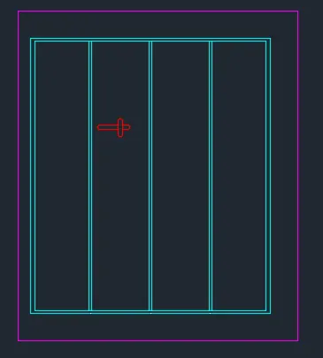
- Change the current layer to text layer
- To create the text
- Click on Annotation tab >multi line
- Manage textile > New
- Style name as > Door 2 > OK
- Font Name > Arial
- Height > 150
- And press set current
- Use multiline text
- And fill the required text at required position
- Click on ANNOTATION tab
- Click on Dimension
- Click > Manage dimension style
- Style name > Project
- Set the characteristics of dimensions as
- Select the yellow colour for the dimension style and extension line
- Select arrowhead size as 50
- Select the text as Cyan colour
- Select Text Style > Door 2
- Then select linear dimensions
- Provide the linear dimension
- And similarly this way, provide the dimensions wherever necessary as shown below
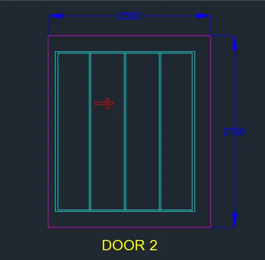
- Take block command by
- type B > enter
- dialogue box will be open
- Name > Door 2
- Click on > Pick point
- Block specify insertion base point > click on any one corner
- Select object > take a cross window and select whole drawing
- Block select object > enter
- Click on > Retain
- Scale uniformly > Mark it by clicking through curser
- Allow exploding > Mark it by clicking through curser as shown below
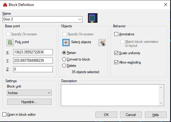
- Click > Ok
- The block is ready
- Result :
- Door 1 :
- Door 2:
PROBLEM 3
- Aim :- To Create each symbol as a block and after creating the blocks arrange them in the legend as shown in the Figure.
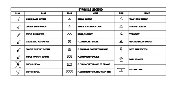
- Introduction :-
The general commands used for drawing the building is as follows :
- Line
- Polygon
- Rectangle
- Circle
- Erase
- Copy
- Trim
- Mirror
- Offset
- Extend
- Array
- Move
- Rotate
- Dimension
- Text
- Fillet
Etc.
- Procedure :-
- Click on AutoCAD application and open this application
- Type QNEW in command bar and enter
- Select default setting as Metric
- In default setting click on use a wizard and in that advance setting and set unit as decimal and precision as 0 and press Next
- Set Angle as Decimal Degree and precision as 0 and click next
- Set Angle Measure as EAST and press NEXT
- Set Angle Direction as Counter-Clockwise and press NEXT
- Set Area by providing Length as 50 and Width as 50
- Press finish
- Keep ortho, Object snap >ON
- Keep Snap and Grid > Off
- Un+enter
- Type > Decimal, Precision > 0
- Units to scale inserted content > milimeter
- Enter
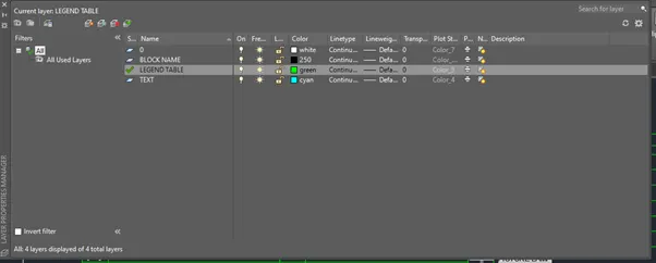
- Click on layer properties
- Click on new layer
- Give the layer name > Legend Table
- Turn the layer ON
- Set Unlock
- Slect layer colour > Green
- Click on new layer
- Give the layer name > Text
- Turn the layer ON
- Set Unlock
- Slect layer colour > Cyan
- Click on new layer
- Give the layer name > Block Name
- Turn the layer ON
- Set Unlock
- Slect layer colour > Black
- The layers which are assigned are shown in below fig
- Set the current layer as legend table layer
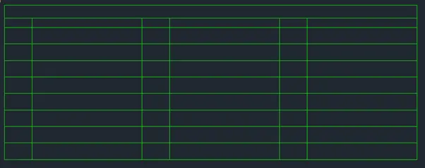
- Take a line command
- Specify first point > Anywhere in the drawing
- Specify next point as > 250 > enter by keeping curser rightside
- Specify next point as > 84 > enter by keeping curser up side
- Specify next point as > 250 > enter by keeping curser leftside
- Specify next point as > 84 > enter by keeping curser downside
- Take offset command
- Specify offset distance > 9
- Specfy object > Click on the bottom horizontal line and take curser upside
- Specify offset distance > 18
- Specfy object > Click on the bottom horizontal line and take curser upside
- Specify offset distance > 27
- Specfy object > Click on the bottom horizontal line and take curser upside
- Specify offset distance > 36
- Specfy object > Click on the bottom horizontal line and take curser upside
- Specify offset distance > 45
- Specfy object > Click on the bottom horizontal line and take curser upside
- Specify offset distance > 54
- Specfy object > Click on the bottom horizontal line and take curser upside
- Specify offset distance > 63
- Specfy object > Click on the bottom horizontal line and take curser upside
- Specify offset distance > 72
- Specfy object > Click on the bottom horizontal line and take curser upside
- Specify offset distance > 77
- Specfy object > Click on the bottom horizontal line and take curser upside
- Specify offset distance > 84
- Specfy object > Click on the bottom horizontal line and take curser upside
- Specify offset distance > 15
- Specfy object > Click on the left vertical line and take curser right side
- Specify offset distance > 75
- Specfy object > Click on the left vertical line and take curser right side
- Specify offset distance > 90
- Specfy object > Click on the left vertical line and take curser right side
- Specify offset distance > 150
- Specfy object > Click on the left vertical line and take curser right side
- Specify offset distance > 165
- Specfy object > Click on the left vertical line and take curser right side
- It will shows us following result
- To create block, change the layer
- Single Gang Switch :
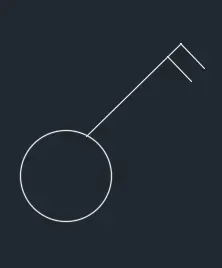
- Use the line command and circle command to draw the single gang switch as shown below

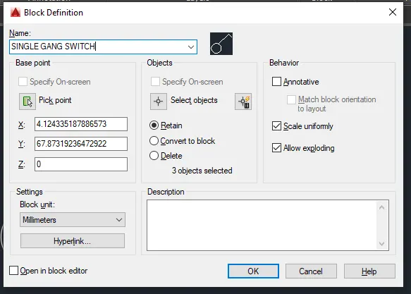
- To create block
- Type b in command bar > enter
- dialogue box will be open
- Name > SINGLE GANG SWITCH
- Click on > Pick point
- Block specify insertion base point > click on centre of circle
- Select object > take a cross window and select whole drawing
- Block select object > enter
- Click on > Retain
- Scale uniformly > Mark it by clicking through curser
- Allow exploding > Mark it by clicking through curser as shown below
- Press > OK
- Block is ready
- Double Gang Switch
- Use the line command and circle command to draw the Double Gang Switch as shown below
- To create block
- Type b in command bar > enter
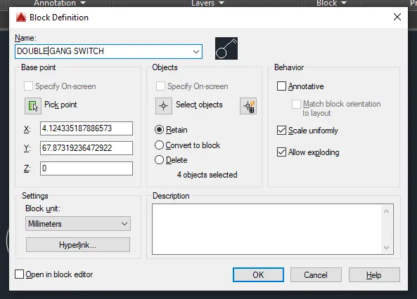
- dialogue box will be open
- Name > DOUBLE GANG SWITCH
- Click on > Pick point
- Block specify insertion base point > click on centre of circle
- Select object > take a cross window and select whole drawing
- Block select object > enter
- Click on > Retain
- Scale uniformly > Mark it by clicking through curser
- Allow exploding > Mark it by clicking through curser as shown below
- Press > OK
- Block is ready
- Triple Gang Switch
- Use the line command and circle command to draw the Double Gang Switch as shown below

- To create block
- Type b in command bar > enter
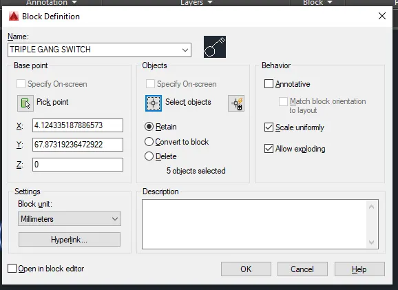
- dialogue box will be open
- Name > TRIPLE GANG SWITCH
- Click on > Pick point
- Block specify insertion base point > click on centre of circle
- Select object > take a cross window and select whole drawing
- Block select object > enter
- Click on > Retain
- Scale uniformly > Mark it by clicking through curser
- Allow exploding > Mark it by clicking through curser as shown below
- Press > OK
- Block is ready
- By this similar way , draw all the following blocks
- Single Two way switch
- Double Two way switch
- Triple Two way switch
- Switch Cross
- Switch Serial
- Sngle Socket
- Single Socket for lamp
- Double Socket
- Floor Socket Single
- Floor Single Socket for Lamp
- Floor Socket Double
- Floor Socket Single Telephone
- Floor Socket Double Telephone
- Teliphone Socket
- Internet Socket
- TV Socket
- Weather Proof Socket
- Dect Base Station
- Wall Bracket
- Picture Lamp
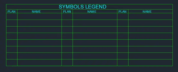
- Change the current layer to text layer
- To create the text
- Click on Annotation tab >multi line
- Manage textile > New
- Style name as > LEGEND > OK
- Font Name > Arial
- Height > 3
- And press set current
- Use multiline text
- And fill the required text at required position
- For SYMBOLS LEGEND, take text height as 5
- It will give us following result
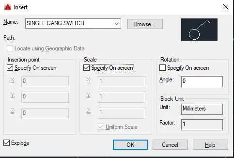
- Take insert command
- Click on drop down
- Select the block which you want to tshow in legend
- Do the setting as per convineance
- Following picture shows the settings I have made
- Press > OK
- Specify insertion point for block
- Then
- After inserting the block
- Insert the block name by
- Click on insert > Field
- It will open a dialogue box
- In dialogue box select field name > Named Object
- Select Name > Single Gang Switch
- Format > Title Case as shown below
- Press OK
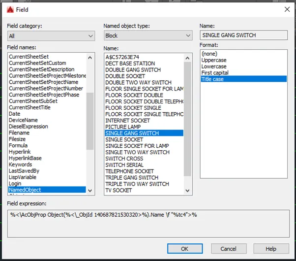
- Similarly Insert all the block name using the similar procedure
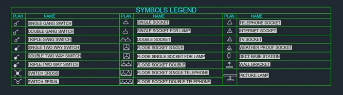
- It will shows the following result
- The legend is ready
- To create block
- Type b in command bar > enter
- dialogue box will be open
- Name > TRIPLE GANG SWITCH
- Click on > Pick point
- Block specify insertion base point > click on centre of circle
- Select object > take a cross window and select whole drawing
- Block select object > enter
- Click on > Retain
- Scale uniformly > Mark it by clicking through curser
- Allow exploding > Mark it by clicking through curser as shown below
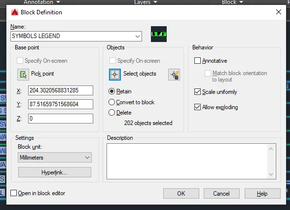
- Press Ok
- The legend with block is ready
- RESULT :-
PROBLEM 4
- Aim :- To Create the door type for residential building as a block and Save the name of the blocks as type.
- Introduction :-
The general commands used for drawing the building is as follows :
- Line
- Polygon
- Rectangle
- Circle
- Erase
- Copy
- Trim
- Mirror
- Offset
- Extend
- Array
- Move
- Rotate
- Dimension
- Text
- Fillet
Etc.
- Procedure :-
1. To Create Door 1 :
- Click on AutoCAD application and open this application
- Type QNEW in command bar and enter
- Select default setting as Imperial
- In default setting click on use a wizard and in that advance setting and set unit as Engineering and precision as 0’0.0” and press Next
- Set Angle as Decimal Degree and precision as 0 and click next
- Set Angle Measure as EAST and press NEXT
- Set Angle Direction as Counter-Clockwise and press NEXT
- Set Area by providing Length as 50 and Width as 50
- Press finish
- Keep ortho, Object snap >ON
- Keep Snap and Grid > Off
- Un+enter
- Type > Decimal, Precision > 0’0.0”
- Units to scale inserted content > inches
- Enter
- Click on layer properties
- Click on new layer
- Give the layer name > Door layer
- Turn the layer ON
- Set Unlock
- Slect layer colour > Yellow
- Click on new layer
- Give the layer name > handle
- Turn the layer ON
- Set Unlock
- Slect layer colour > Green
- The layers which are assigned are shown in below fig
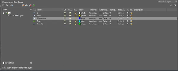
- Set the current layer as Template Table
- Take a line command
- Specify first point > Anywhere in the drawing
- Specify next point > 2’10” > keeping the curser right side > enter
- Specify next point > 6’11” > keeping the curser upside > enter
- Specify next point > 2’10” > keeping the curser left side > enter
- Specify next point > 6’11” > keeping the curser down side > enter
- Take offset command
- Specify offset distance > 2” > Enter
- Specify object as > Click on the Left side vertical line and take curser rightside
- Specify offset distance > 2”> Enter
- Specify object as > Click on the last offset created line and take curser rightside
- Specify offset distance > 2” > Enter
- Specify object as > Click on the right side vertical line and take curser leftside
- Specify offset distance > 2”> Enter
- Specify object as > Click on the last offset created line and take curser leftside
- Specify offset distance > 2” > Enter
- Specify object as > Click on the top horizontal line and take curser down side
- Specify offset distance > 2”> Enter
- Specify object as > Click on the last offset created line and take curser downside
- Change the current layer to handle layer
- Use the rectangle and circle command to show the door handle
- Change the current layer to text layer
- To create the text
- Click on Annotation tab >multi line
- Manage textile > New
- Style name as > D1 > OK
- Font Name > Arial
- Height > 3
- And press set current
- Use multiline text
- And fill the required text at required position
- Click on ANNOTATION tab
- Click on Dimension
- Click > Manage dimension style
- Style name > D1
- Set the characteristics of dimensions as
- Select the yellow colour for the dimension style and extension line
- Select arrowhead size as 3”
- Select the text as Cyan colour
- Select Text Style > Door 1
- Then select linear dimensions
- Provide the linear dimension
- And similarly this way, provide the dimensions wherever necessary as shown below
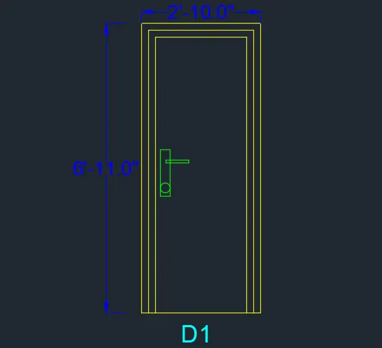
- To create block
- Type b in command bar > enter
- dialogue box will be open
- Name > Door 1
- Click on > Pick point
- Block specify insertion base point > click on centre of circle
- Select object > take a cross window and select whole drawing
- Block select object > enter
- Click on > Retain
- Scale uniformly > Mark it by clicking through curser
- Allow exploding > Mark it by clicking through curser as shown below
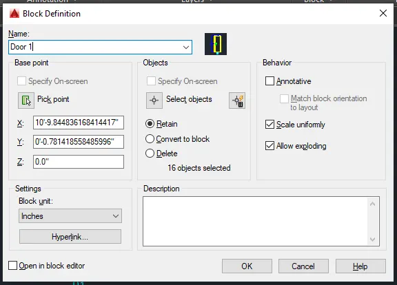
- Press > Ok
- The block is ready
2. To Create Door 2 :
- Click on AutoCAD application and open this application
- Type QNEW in command bar and enter
- Select default setting as Imperial
- In default setting click on use a wizard and in that advance setting and set unit as Engineering and precision as 0’0.0” and press Next
- Set Angle as Decimal Degree and precision as 0 and click next
- Set Angle Measure as EAST and press NEXT
- Set Angle Direction as Counter-Clockwise and press NEXT
- Set Area by providing Length as 50 and Width as 50
- Press finish
- Keep ortho, Object snap >ON
- Keep Snap and Grid > Off
- Un+enter
- Type > Decimal, Precision > 0’0.0”
- Units to scale inserted content > inches
- Enter
- Click on layer properties
- Click on new layer
- Give the layer name > Door layer
- Turn the layer ON
- Set Unlock
- Slect layer colour > Yellow
- Click on new layer
- Give the layer name > handle
- Turn the layer ON
- Set Unlock
- Slect layer colour > Green
- The layers which are assigned are shown in below fig
- Set the current layer as Template Table
- Take a line command
- Specify first point > Anywhere in the drawing
- Specify next point > 3’4” > keeping the curser right side > enter
- Specify next point > 6’11” > keeping the curser upside > enter
- Specify next point > 3’4” > keeping the curser left side > enter
- Specify next point > 6’11” > keeping the curser down side > enter
- Take offset command
- And provide the offset as per requirement as shown below
- Change the current layer to handle layer
- Use the circle command to show the door handle
- Change the current layer to text layer
- To create the text
- Click on Annotation tab >multi line
- Manage textile > New
- Style name as > D2 > OK
- Font Name > Arial
- Height > 3
- And press set current
- Use multiline text
- And fill the required text at required position
- Click on ANNOTATION tab
- Click on Dimension
- Click > Manage dimension style
- Style name > D2
- Set the characteristics of dimensions as
- Select the yellow colour for the dimension style and extension line
- Select arrowhead size as 3”
- Select the text as Cyan colour
- Select Text Style > Door 2
- Then select linear dimensions
- Provide the linear dimension
- And similarly this way, provide the dimensions wherever necessary as shown below
- To create block
- Type b in command bar > enter
- dialogue box will be open
- Name > Door 2
- Click on > Pick point
- Block specify insertion base point > click on centre of circle
- Select object > take a cross window and select whole drawing
- Block select object > enter
- Click on > Retain
- Scale uniformly > Mark it by clicking through curser
- Allow exploding > Mark it by clicking through curser as shown below
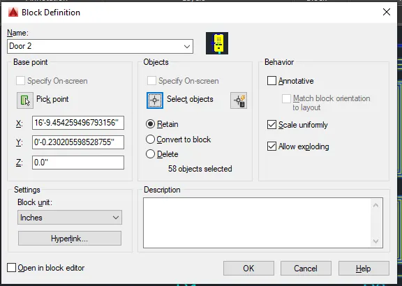
- Press > OK
- The block is ready
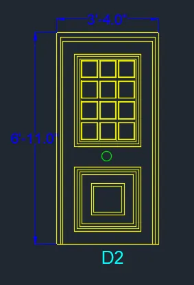
3. To Create Door 3 :
- Click on AutoCAD application and open this application
- Type QNEW in command bar and enter
- Select default setting as Imperial
- In default setting click on use a wizard and in that advance setting and set unit as Engineering and precision as 0’0.0” and press Next
- Set Angle as Decimal Degree and precision as 0 and click next
- Set Angle Measure as EAST and press NEXT
- Set Angle Direction as Counter-Clockwise and press NEXT
- Set Area by providing Length as 50 and Width as 50
- Press finish
- Keep ortho, Object snap >ON
- Keep Snap and Grid > Off
- Un+enter
- Type > Decimal, Precision > 0’0.0”
- Units to scale inserted content > inches
- Enter
- Click on layer properties
- Click on new layer
- Give the layer name > Door layer
- Turn the layer ON
- Set Unlock
- Slect layer colour > Yellow
- Click on new layer
- Give the layer name > handle
- Turn the layer ON
- Set Unlock
- Slect layer colour > Green
- The layers which are assigned are shown in below fig
- Set the current layer as Template Table
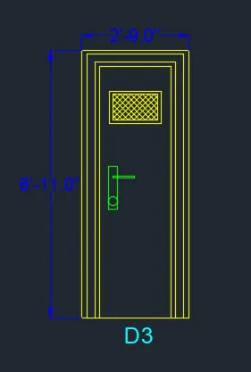
- Take a line command
- Specify first point > Anywhere in the drawing
- Specify next point > 2’9” > keeping the curser right side > enter
- Specify next point > 6’11” > keeping the curser upside > enter
- Specify next point > 2’9” > keeping the curser left side > enter
- Specify next point > 6’11” > keeping the curser down side > enter
- Take offset command
- And provide the offset as per requirement as shown below
- Change the current layer to handle layer
- Use the rectangle command and circle command to show the door handle
- Change the current layer to text layer
- To create the text
- Click on Annotation tab >multi line
- Manage textile > New
- Style name as > D3 > OK
- Font Name > Arial
- Height > 3
- And press set current
- Use multiline text
- And fill the required text at required position
- Click on ANNOTATION tab
- Click on Dimension
- Click > Manage dimension style
- Style name > D3
- Set the characteristics of dimensions as
- Select the yellow colour for the dimension style and extension line
- Select arrowhead size as 3”
- Select the text as Cyan colour
- Select Text Style > Door 3
- Then select linear dimensions
- Provide the linear dimension
- And similarly this way, provide the dimensions wherever necessary as shown below
- To create block
- Type b in command bar > enter
- dialogue box will be open
- Name > Door 3
- Click on > Pick point
- Block specify insertion base point > click on centre of circle
- Select object > take a cross window and select whole drawing
- Block select object > enter
- Click on > Retain
- Scale uniformly > Mark it by clicking through curser
- Allow exploding > Mark it by clicking through curser as shown below
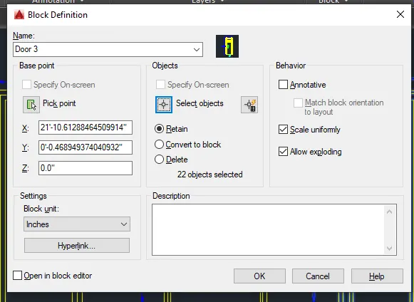
- Click > OK
- The block is ready
4. To Create Door 4 :
- Click on AutoCAD application and open this application
- Type QNEW in command bar and enter
- Select default setting as Imperial
- In default setting click on use a wizard and in that advance setting and set unit as Engineering and precision as 0’0.0” and press Next
- Set Angle as Decimal Degree and precision as 0 and click next
- Set Angle Measure as EAST and press NEXT
- Set Angle Direction as Counter-Clockwise and press NEXT
- Set Area by providing Length as 50 and Width as 50
- Press finish
- Keep ortho, Object snap >ON
- Keep Snap and Grid > Off
- Un+enter
- Type > Decimal, Precision > 0’0.0”
- Units to scale inserted content > inches
- Enter
- Click on layer properties
- Click on new layer
- Give the layer name > Door layer
- Turn the layer ON
- Set Unlock
- Slect layer colour > Yellow
- Click on new layer
- Give the layer name > handle
- Turn the layer ON
- Set Unlock
- Slect layer colour > Green
- The layers which are assigned are shown in below fig
- Set the current layer as Template Table
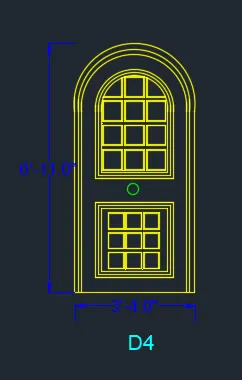
- Take a line command
- Specify first point > Anywhere in the drawing
- Specify next point > 3’4” > keeping the curser right side > enter
- Specify next point > 6’11” > keeping the curser upside > enter
- Specify next point > 3’4” > keeping the curser left side > enter
- Specify next point > 6’11” > keeping the curser down side > enter
- Take offset command
- And provide the offset as per requirement and also use the arc command as shown below
- Change the current layer to handle layer
- Use the circle command to show the door handle
- Change the current layer to text layer
- To create the text
- Click on Annotation tab >multi line
- Manage textile > New
- Style name as > D4 > OK
- Font Name > Arial
- Height > 3
- And press set current
- Use multiline text
- And fill the required text at required position
- Click on ANNOTATION tab
- Click on Dimension
- Click > Manage dimension style
- Style name > D4
- Set the characteristics of dimensions as
- Select the yellow colour for the dimension style and extension line
- Select arrowhead size as 3”
- Select the text as Cyan colour
- Select Text Style > Door 4
- Then select linear dimensions
- Provide the linear dimension
- And similarly this way, provide the dimensions wherever necessary as shown below
- To create block
- Type b in command bar > enter
- dialogue box will be open
- Name > Door 4
- Click on > Pick point
- Block specify insertion base point > click on centre of circle
- Select object > take a cross window and select whole drawing
- Block select object > enter
- Click on > Retain
- Scale uniformly > Mark it by clicking through curser
- Allow exploding > Mark it by clicking through curser as shown below
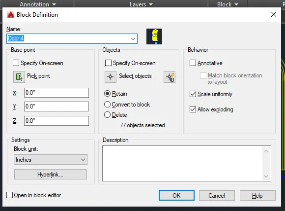
- Press > OK
- The block is ready
5. To Create Door 5 :
- Click on AutoCAD application and open this application
- Type QNEW in command bar and enter
- Select default setting as Imperial
- In default setting click on use a wizard and in that advance setting and set unit as Engineering and precision as 0’0.0” and press Next
- Set Angle as Decimal Degree and precision as 0 and click next
- Set Angle Measure as EAST and press NEXT
- Set Angle Direction as Counter-Clockwise and press NEXT
- Set Area by providing Length as 50 and Width as 50
- Press finish
- Keep ortho, Object snap >ON
- Keep Snap and Grid > Off
- Un+enter
- Type > Decimal, Precision > 0’0.0”
- Units to scale inserted content > inches
- Enter
- Click on layer properties
- Click on new layer
- Give the layer name > Door layer
- Turn the layer ON
- Set Unlock
- Slect layer colour > Yellow
- Click on new layer
- Give the layer name > handle
- Turn the layer ON
- Set Unlock
- Slect layer colour > Green
- The layers which are assigned are shown in below fig
- Set the current layer as Template Table
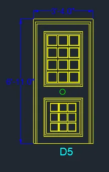
- Take a line command
- Specify first point > Anywhere in the drawing
- Specify next point > 3’4” > keeping the curser right side > enter
- Specify next point > 6’11” > keeping the curser upside > enter
- Specify next point > 3’4” > keeping the curser left side > enter
- Specify next point > 6’11” > keeping the curser down side > enter
- Take offset command
- And provide the offset as per requirement and rectangle command as shown below
- Change the current layer to handle layer
- Use the circle command to show the door handle
- Change the current layer to text layer
- To create the text
- Click on Annotation tab >multi line
- Manage textile > New
- Style name as > D5 > OK
- Font Name > Arial
- Height > 3
- And press set current
- Use multiline text
- And fill the required text at required position
- Click on ANNOTATION tab
- Click on Dimension
- Click > Manage dimension style
- Style name > D5
- Set the characteristics of dimensions as
- Select the yellow colour for the dimension style and extension line
- Select arrowhead size as 3”
- Select the text as Cyan colour
- Select Text Style > Door 5
- Then select linear dimensions
- Provide the linear dimension
- And similarly this way, provide the dimensions wherever necessary as shown below
- To create block
- Type b in command bar > enter
- dialogue box will be open
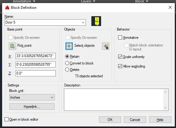
- Name > Door 5
- Click on > Pick point
- Block specify insertion base point > click on centre of circle
- Select object > take a cross window and select whole drawing
- Block select object > enter
- Click on > Retain
- Scale uniformly > Mark it by clicking through curser
- Allow exploding > Mark it by clicking through curser as shown below
- Press > Ok
- The block is ready
6. To Create Door 6 :
- Click on AutoCAD application and open this application
- Type QNEW in command bar and enter
- Select default setting as Imperial
- In default setting click on use a wizard and in that advance setting and set unit as Engineering and precision as 0’0.0” and press Next
- Set Angle as Decimal Degree and precision as 0 and click next
- Set Angle Measure as EAST and press NEXT
- Set Angle Direction as Counter-Clockwise and press NEXT
- Set Area by providing Length as 50 and Width as 50
- Press finish
- Keep ortho, Object snap >ON
- Keep Snap and Grid > Off
- Un+enter
- Type > Decimal, Precision > 0’0.0”
- Units to scale inserted content > inches
- Enter
- Click on layer properties
- Click on new layer
- Give the layer name > Door layer
- Turn the layer ON
- Set Unlock
- Slect layer colour > Yellow
- Click on new layer
- Give the layer name > handle
- Turn the layer ON
- Set Unlock
- Slect layer colour > Green
- The layers which are assigned are shown in below fig
- Set the current layer as Template Table
- Take a line command
- Specify first point > Anywhere in the drawing
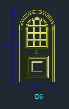
- Specify next point > 3’4” > keeping the curser right side > enter
- Specify next point > 6’11” > keeping the curser upside > enter
- Specify next point > 3’4” > keeping the curser left side > enter
- Specify next point > 6’11” > keeping the curser down side > enter
- Take offset command
- And provide the offset as per requirement and rectangle command as shown below
- Change the current layer to handle layer
- Use the circle command to show the door handle
- Change the current layer to text layer
- To create the text
- Click on Annotation tab >multi line
- Manage textile > New
- Style name as > D5 > OK
- Font Name > Arial
- Height > 3
- And press set current
- Use multiline text
- And fill the required text at required position
- Click on ANNOTATION tab
- Click on Dimension
- Click > Manage dimension style
- Style name > D5
- Set the characteristics of dimensions as
- Select the yellow colour for the dimension style and extension line
- Select arrowhead size as 3”
- Select the text as Cyan colour
- Select Text Style > Door 5
- Then select linear dimensions
- Provide the linear dimension
- And similarly this way, provide the dimensions wherever necessary as shown below
- To create block
- Type b in command bar > enter
- dialogue box will be open
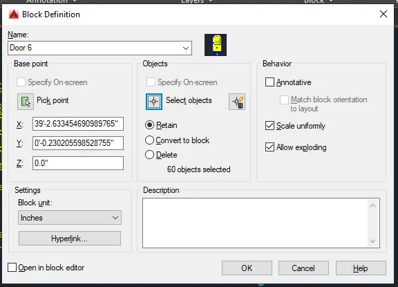
- Name > Door 5
- Click on > Pick point
- Block specify insertion base point > click on centre of circle
- Select object > take a cross window and select whole drawing
- Block select object > enter
- Click on > Retain
- Scale uniformly > Mark it by clicking through curser
- Allow exploding > Mark it by clicking through curser as shown below
- Press > OK
- The block is ready
- RESULT :-
- D1
- D2
- D3
- D4
- D5
- D6
PROBLEM 4
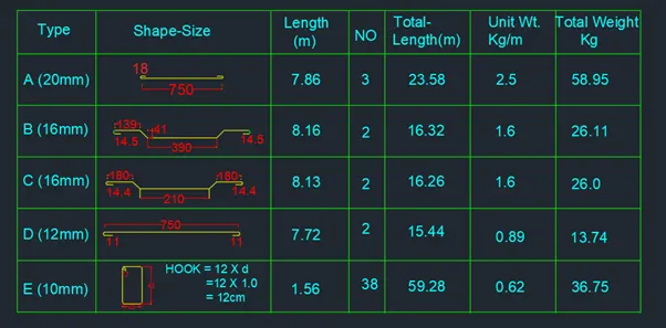
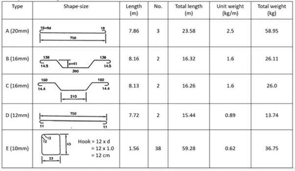
- Aim :- To Create the block of each reinforcement and insert that block in table as shown below to create the Bar Bending Schedule
- Introduction :-
The general commands used for drawing the building is as follows :
- Line
- Polygon
- Rectangle
- Circle
- Erase
- Copy
- Trim
- Mirror
- Offset
- Extend
- Array
- Move
- Rotate
- Dimension
- Text
- Fillet
etc
- Procedure :-
- Click on AutoCAD application and open this application
- Type QNEW in command bar and enter
- Select default setting as Metric
- In default setting click on use a wizard and in that advance setting and set unit as decimal and precision as 0 and press Next
- Set Angle as Decimal Degree and precision as 0 and click next
- Set Angle Measure as EAST and press NEXT
- Set Angle Direction as Counter-Clockwise and press NEXT
- Set Area by providing Length as 50 and Width as 50
- Press finish
- Keep ortho, Object snap >ON
- Keep Snap and Grid > Off
- Un+enter
- Type > Decimal, Precision > 0
- Units to scale inserted content > Centimeter
- Enter
- Click on layer properties
- Click on new layer
- Give the layer name > Table
- Turn the layer ON
- Set Unlock
- Slect layer colour > Green
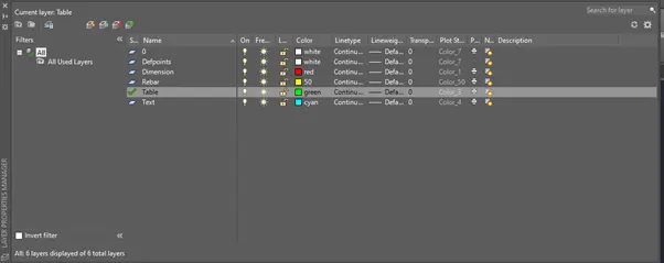
- Similarly provide all the layers
- The layers which are assigned are shown in below fig
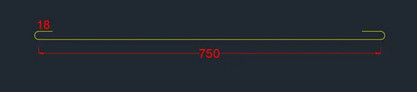
- To create the block for rebar Type A
- Take a line command
- Specify first point > Anywhere in the drawing
- Specify next point as > 750 > enter by keeping curser rightside
- Enter
- Use the circle command to show bend
- To create block for this
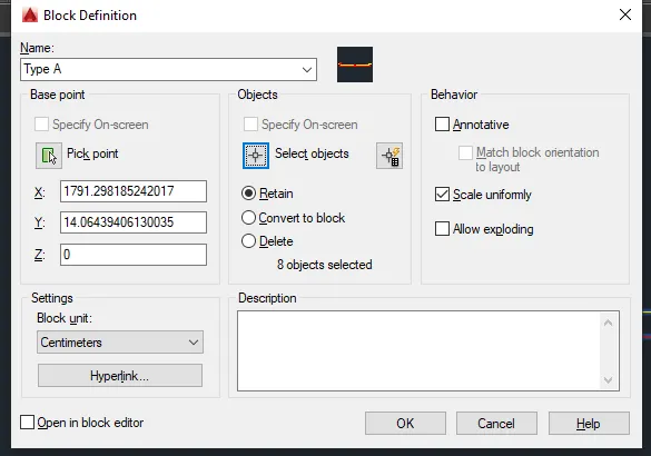
- Type b in command bar > enter
- dialogue box will be open
- Name > Door 5
- Click on > Pick point
- Block specify insertion base point > click on centre of circle
- Select object > take a cross window and select whole drawing
- Block select object > enter
- Click on > Retain
- Scale uniformly > Mark it by clicking through curser
- Allow exploding > Mark it by clicking through curser as shown below
- Press > Ok
- The block for Type A is ready
- Similarly do the block for Type B, Type C, Type D and Type E
- Change the current layer to table layer
- Draw the table by using line and offset command
- Change the current layer to text layer
- To create the text
- Click on Annotation tab >multi line
- Manage textile > New
- Style name as > D5 > OK
- Font Name > Arial
- Height > 3
- And press set current
- Use multiline text
- And fill the required text at required position
- To insert the blocks created
- Take insert command
- Select the block
- And do settings as per convineance
- And specify the insertion point to locate the block position
- Enter
- Click on ANNOTATION tab
- Click on Dimension
- Click > Manage dimension style
- Style name > D5
- Set the characteristics of dimensions as
- Select the yellow colour for the dimension style and extension line
- Select arrowhead size as 3”
- Select the text as Cyan colour
- Select Text Style > Door 5
- Then select linear dimensions
- Provide the linear dimension
- And similarly this way, provide the dimensions wherever necessary as shown below
- The bar bending schedule is ready
- RESULT :-