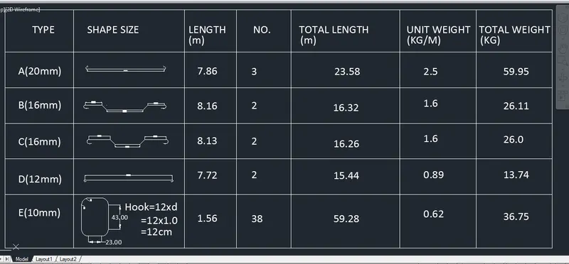
Creating Bar Bending schedule, Different Door types, and Creation of standard drawing templates using AutoCad
1) Aim: To design and draft a layout of a resedential building using given details like plot size and orientation
Procedure:
Go to start menu and select the autocad 2014 software click on that
And go to command tab and type Startup command
Give startup value as 1
Go to application menu and go to new option
Create new drawing dialogue box opens
Select units as decimal and precision 0.0 and press finish
And go to units and select units as decimal and precision 0.0 and insertion scale as meters
Then go to limits command and specify lower left corner as 500m and upper right corner as 500m
Go to layout and select template by right clicking on the layout
Select page setup manager by right clicking on the layout
The pagesetup dialogue box appears
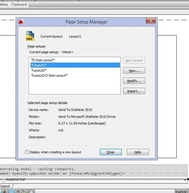
Select layout and Click on modify option and page setup dialogue box opens
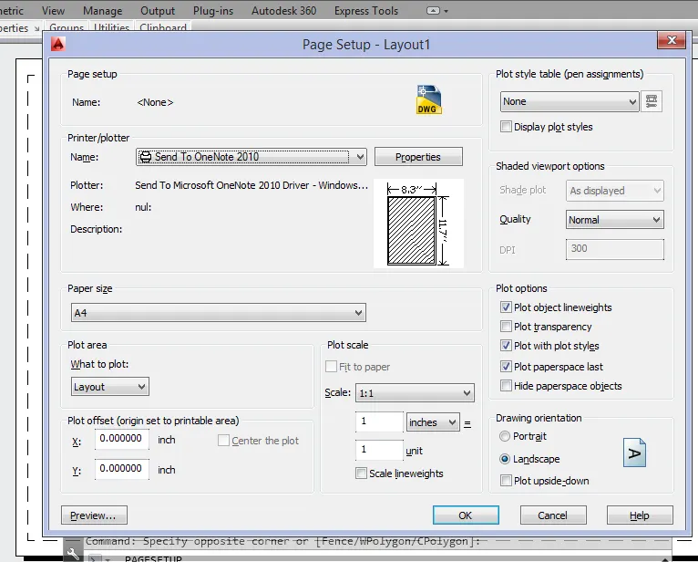
Select name as none option and paper size as ISO A4(210.00X297.00MM)
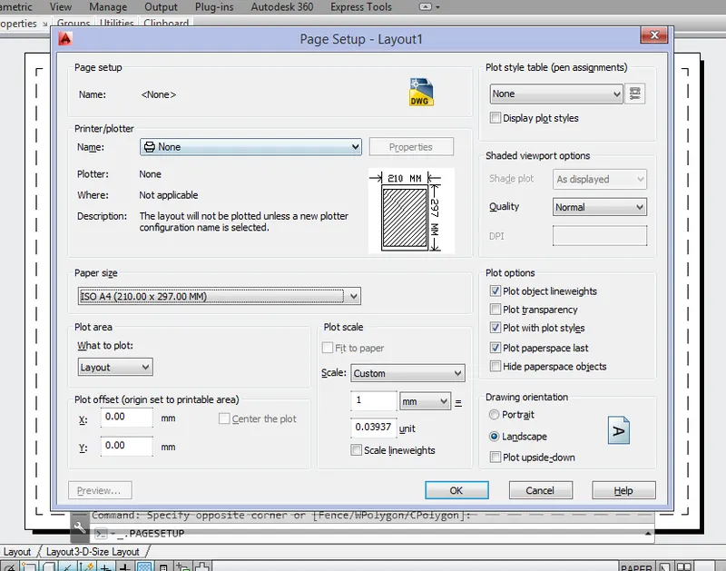
And specify drawing orientation as landscape and press ok
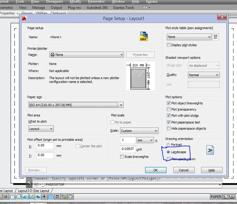
Now insert a table inside a template file and insert table dialogue box opens
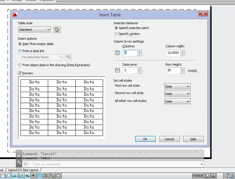
Insert the table inside the template using insert option
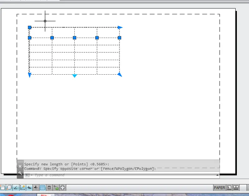
Modify the table as we want to edit the table
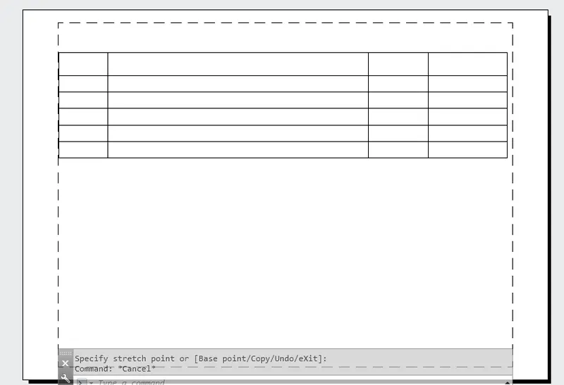
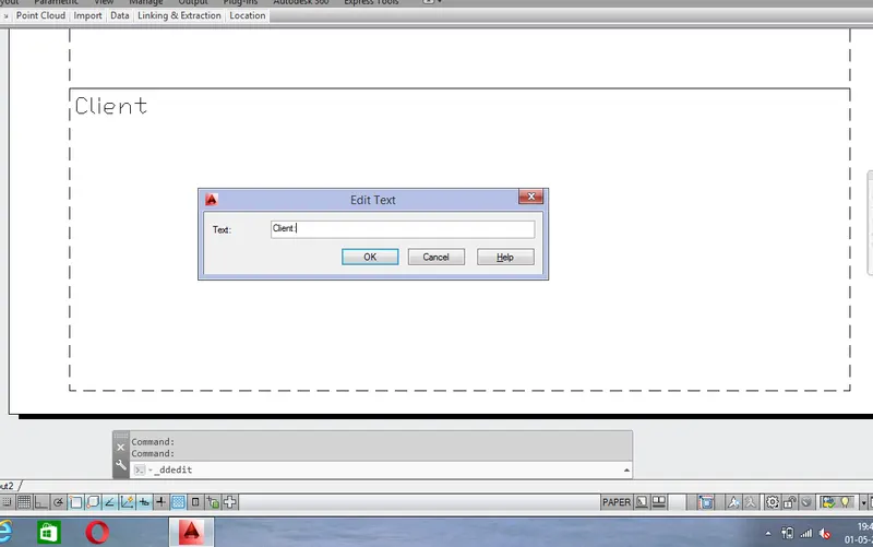
Go to text command and insert the text using text command
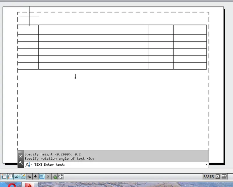
Insert the given text inside the template
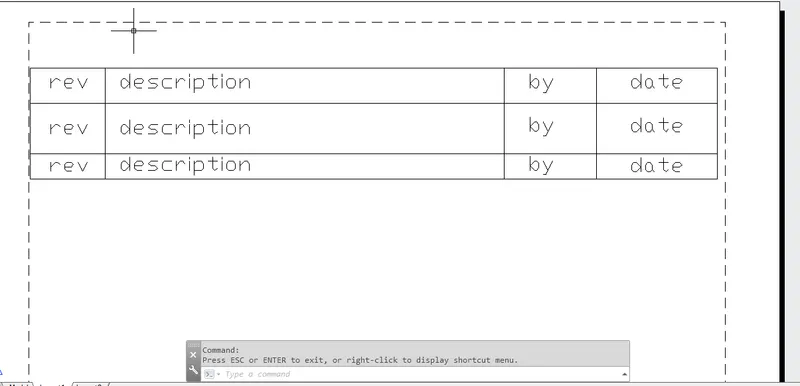
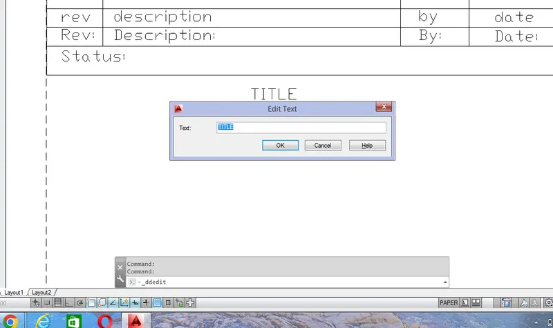
Go to line command and draw a line using line tool
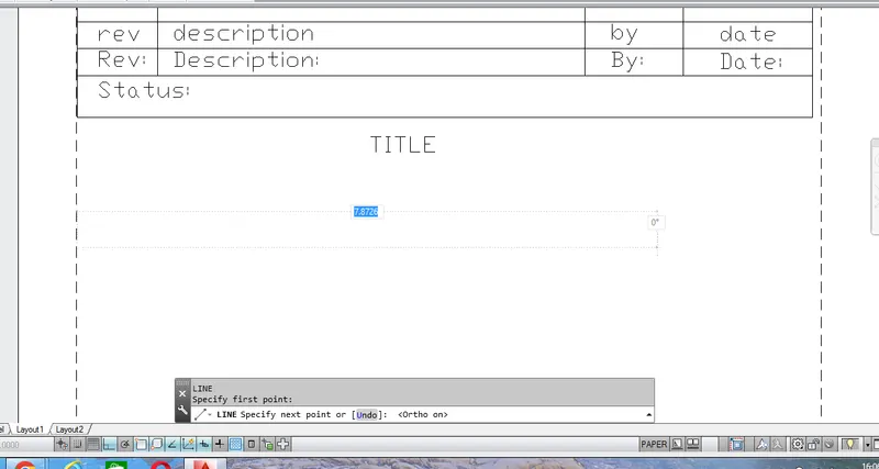
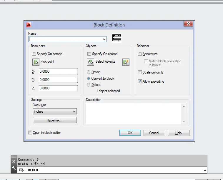
Convert this created layout as a block by using block command
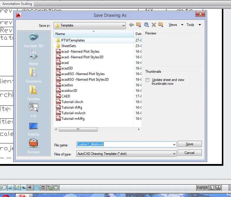
And save it in the name of custom1_titleblock in the save as option and in drawing template path
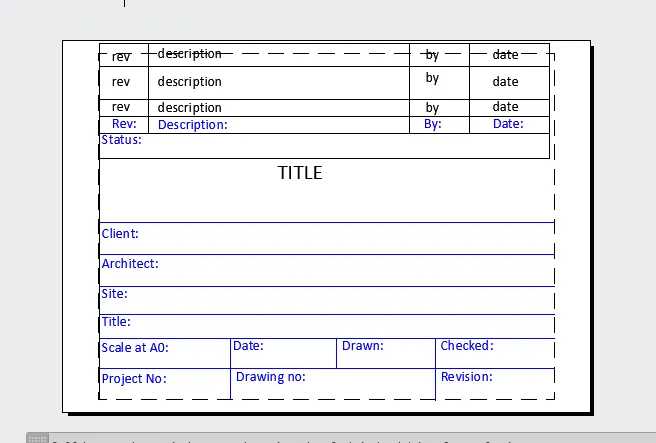
Result:
b)
Select page setup manager by right clicking on the layout
The pagesetup dialogue box appears
Select layout and Click on modify option and page setup dialogue box opens
Select name as none option and paper size as ISO A4(210.00X297.00MM)
And specify drawing orientation as landscape and press ok
Take a line command and draw a line using line tool
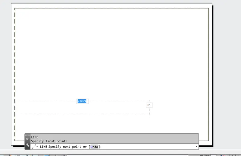
Again draw a line using line tool
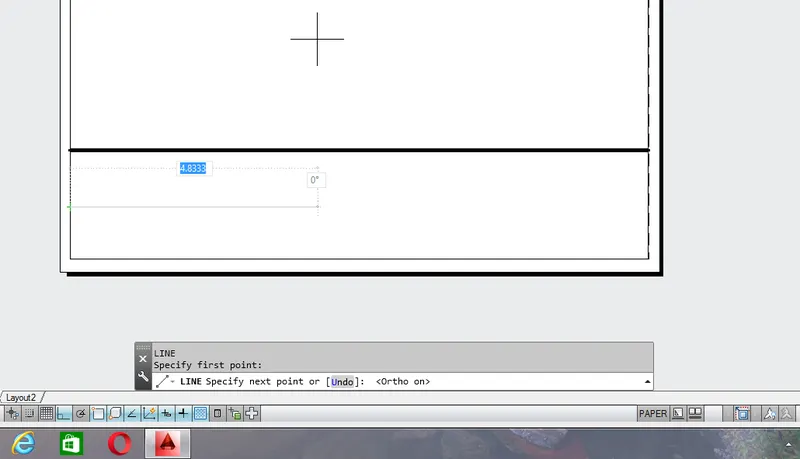
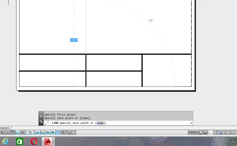
Now add a text using text command
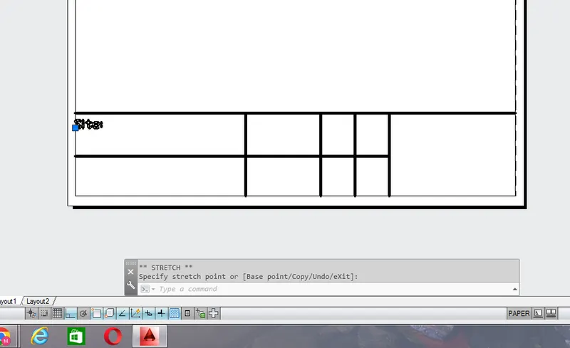
Again draw one table over here using line tool
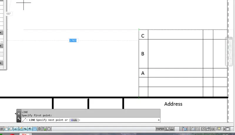
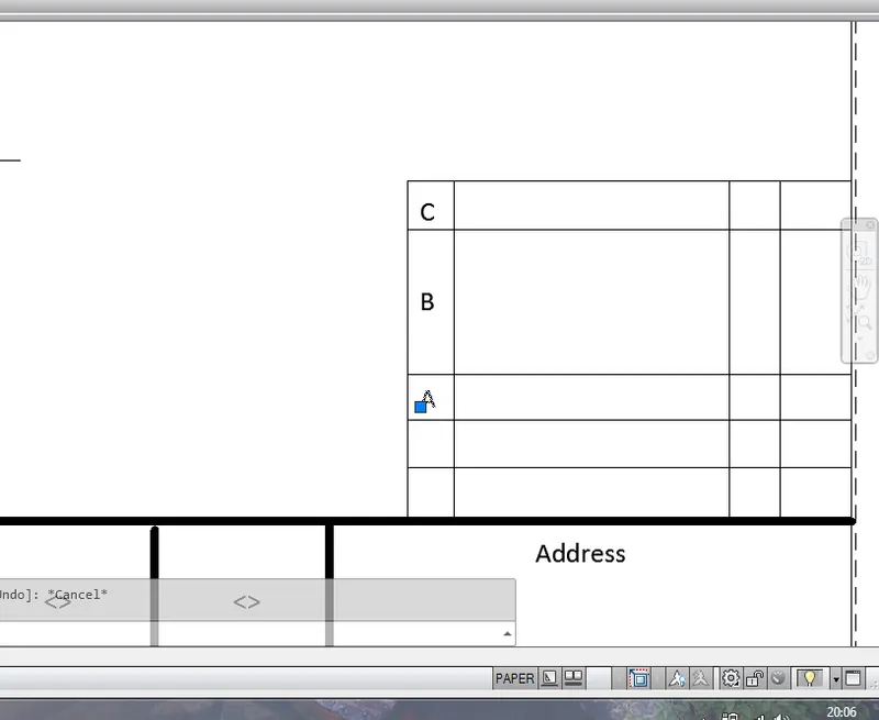
Add a suitable text inside the table using text command
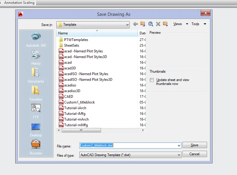
Save this template as Custom2_titleblock in the save as option and in drawing template path
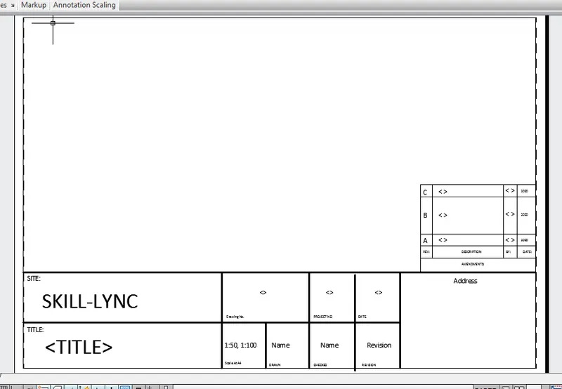
Result:
2)
Aim: To design and draft given type of door using given dimensions
Procedure:
Go to start menu and select the autocad 2014 software click on that
And go to command tab and type Startup command
Give startup value as 1
Go to application menu and go to new option
Create new drawing dialogue box opens
Select units as decimal and precision 0.0 and press finish
And go to units and select units as decimal and precision 0.0 and insertion scale as millimeters
Then go to limits command and specify lower left corner as 500mm and upper right corner as 500mm
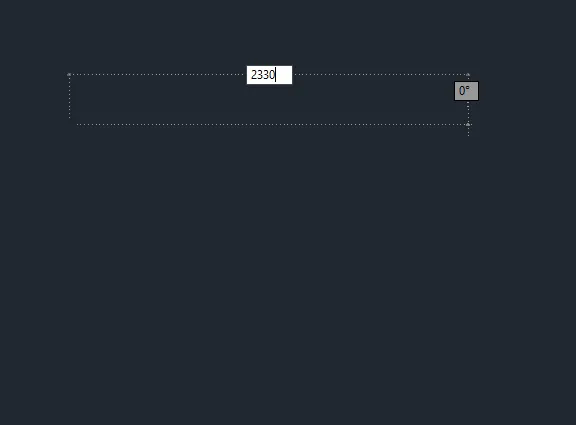
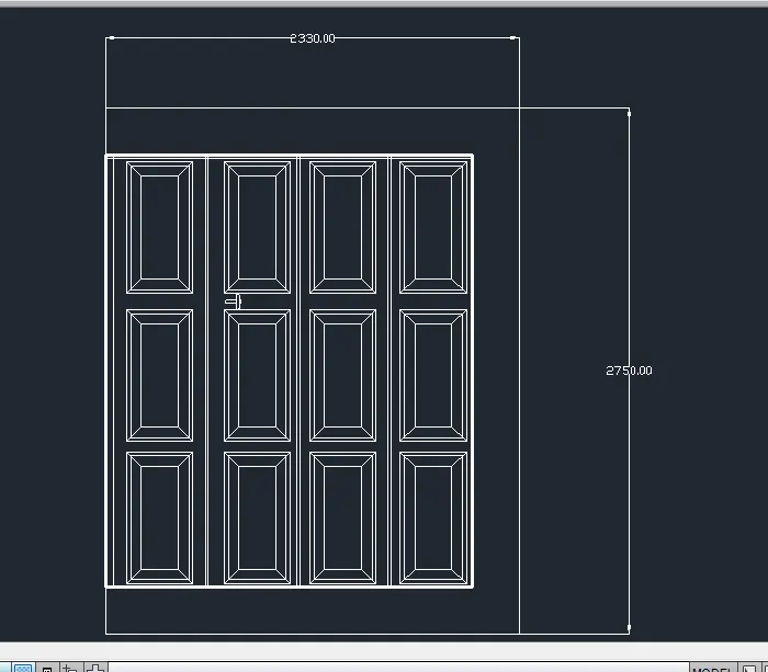
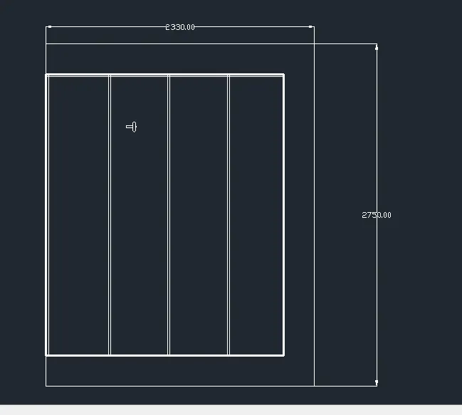
Go to line command and draw a line of length 2330mm using line tool and draw a door
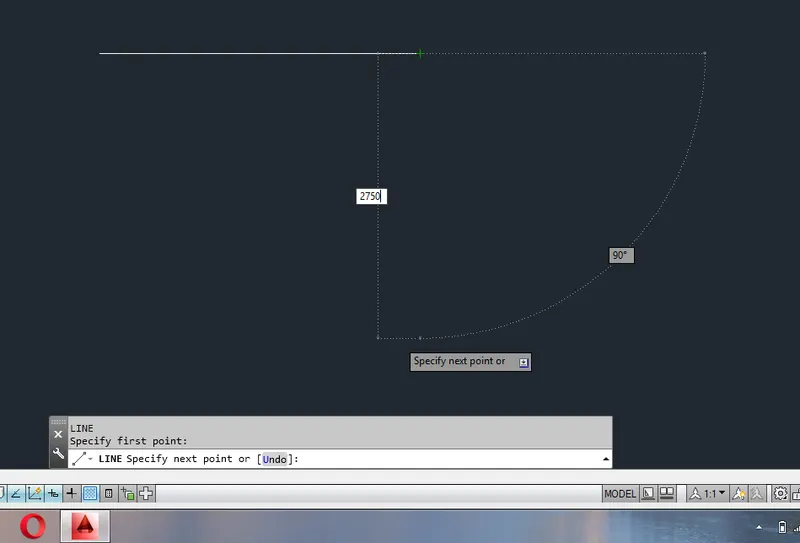
Again draw a line of length 2750mm using line tool
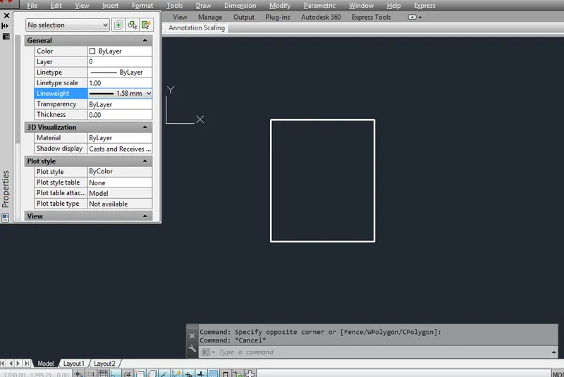
Change the line type to thickness using LW command and the properties of line will changes
Draw a line inside the door to indicate the thickness of the door
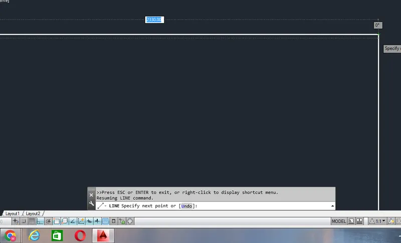
Draw a line vertically using line command of length 2750mm using line tool
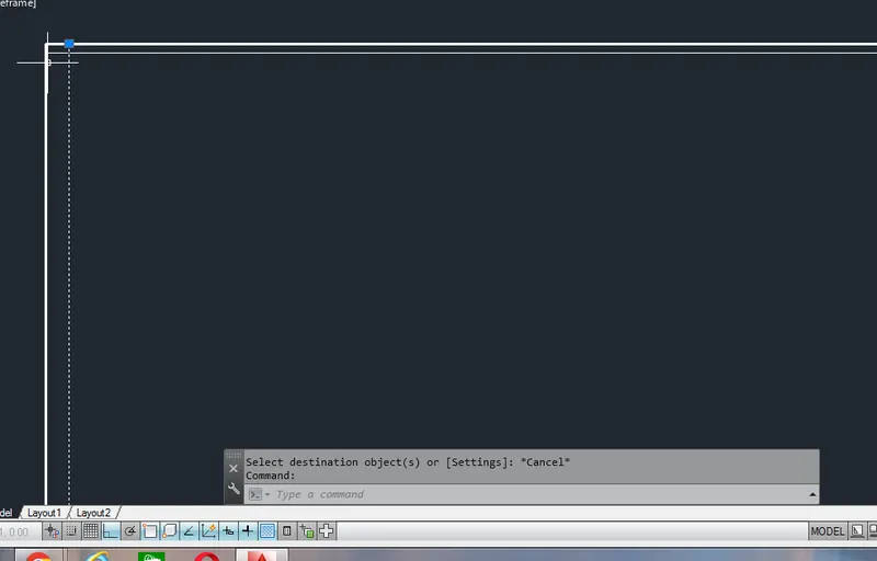
Draw a equal no of offsets to draw a panel of a door using line command
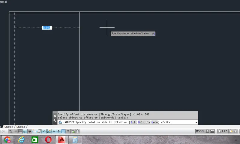
To draw a panel of a door, take panel door size as 24.3mm vertically downwards
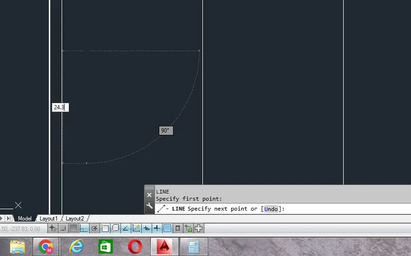
Take a offset of 15mm using offset tool inside the door panel
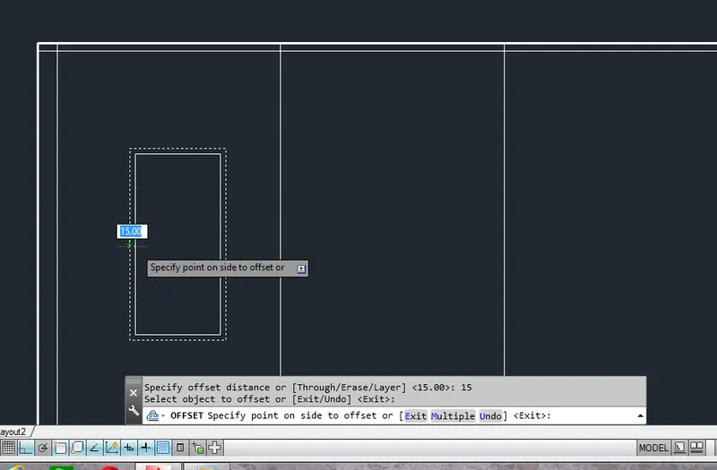
Again take a offset of 40mm inside the created offset line using offset tool
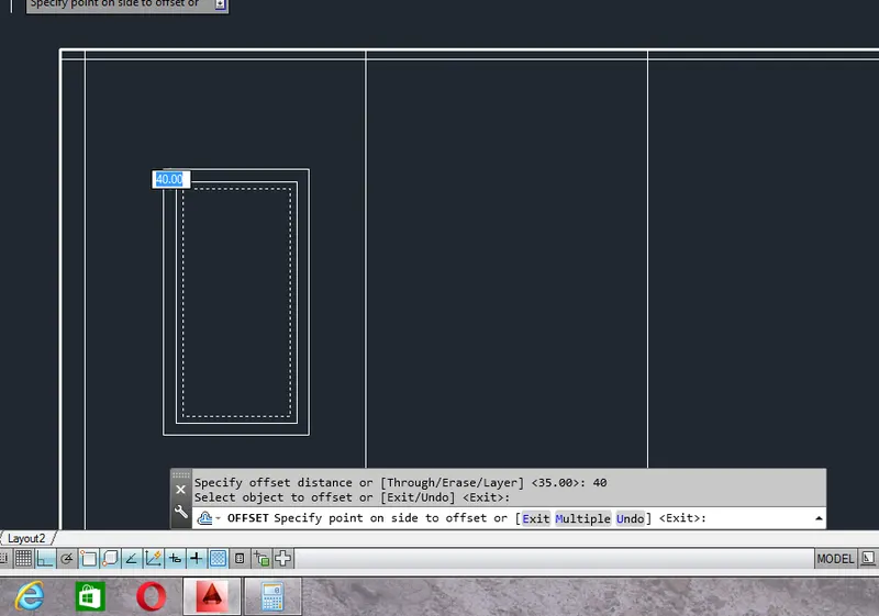
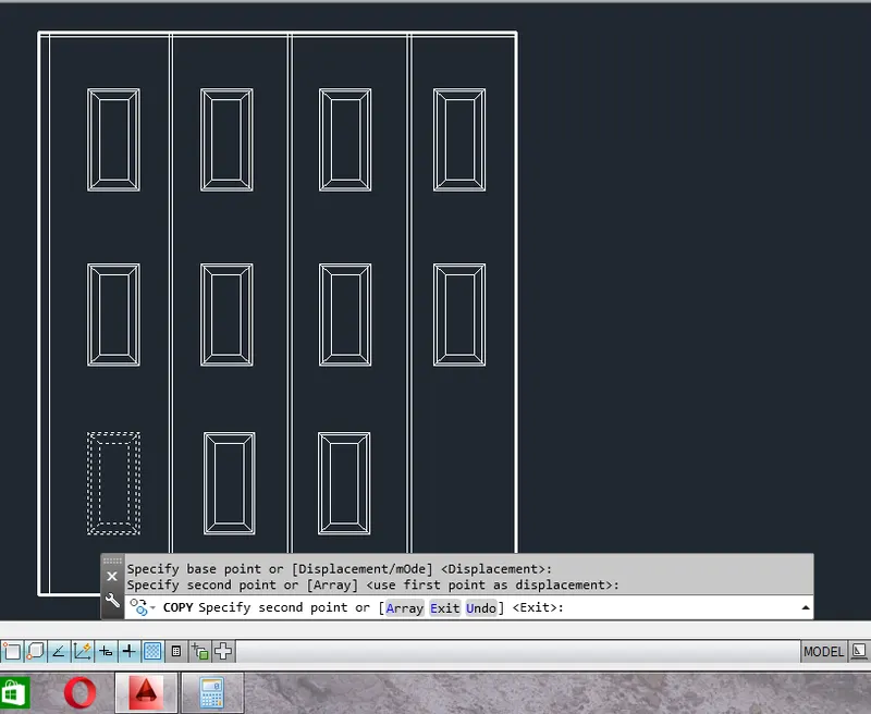
Copy the door panel using copy command using copy tool
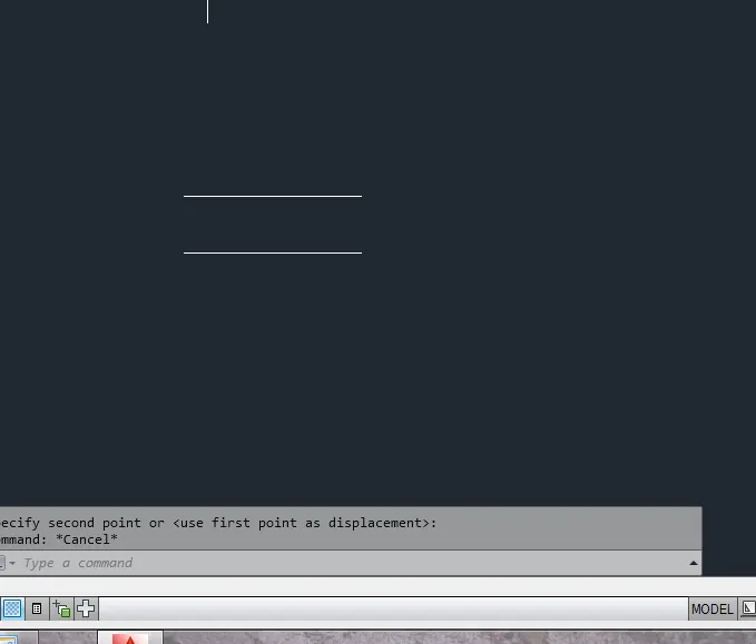
To create a hardware of a door take line tool and draw a two small parralel lines
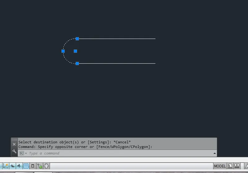
Create a arc at the edges of the line using arc command.
Copy the object and rotate it to the 90degress and place on the object
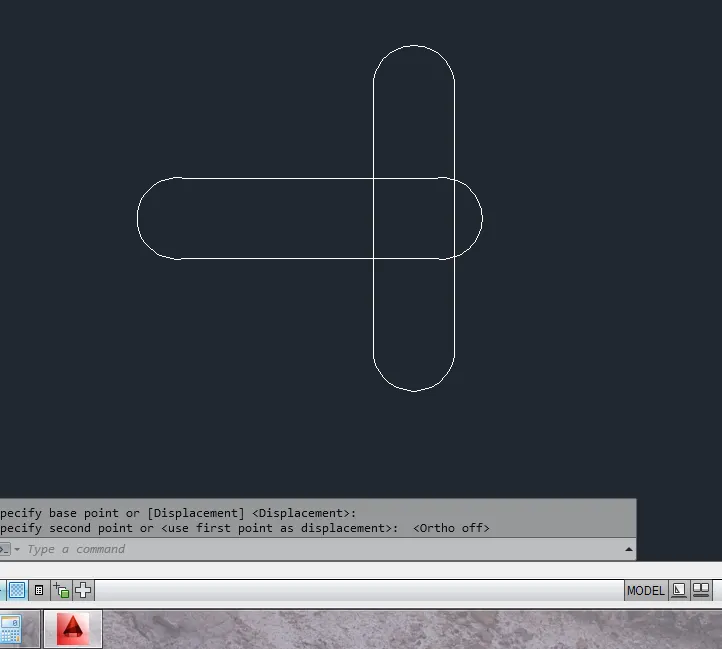
Trim out the inside line using trim command
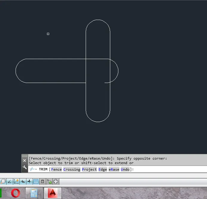
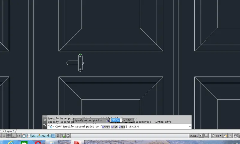
Place the hardware on the door to enable the locking of a door purpose
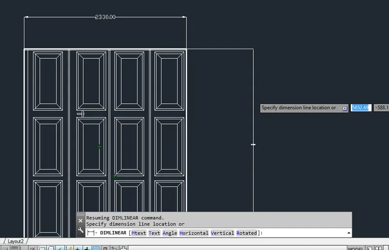
Now take dimlinear command and measure the length and width of the door
In order to convert this door into a block go to block command
Block definition dialogue box opens and give a name for the door as Door 1 and select obejcts there
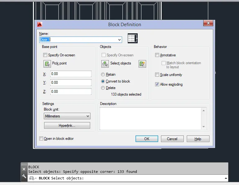
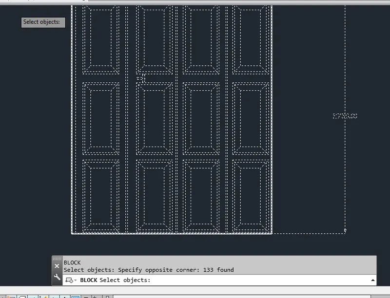
And press enter and specify a point from pick point option and press ok
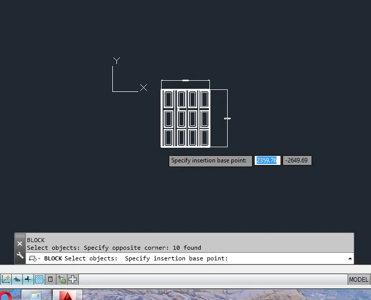
Finally the door 1 block is created
Result:
b) In order to create a door 2 take a line command and draw a line of length 2330mm horizontaly using line tool
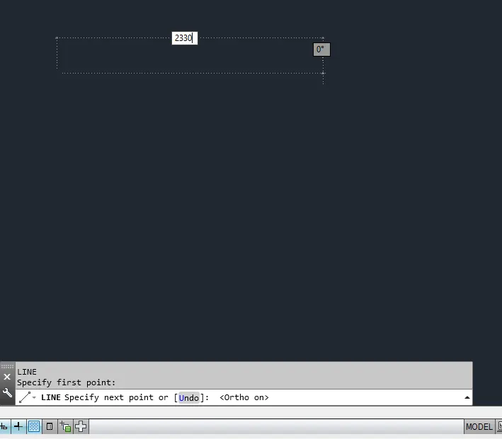
Again draw a line of length 2750mm in vertical direction using line tool
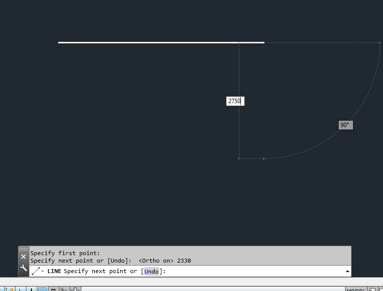
Take a line of length 15mm line inside the door using line command in horizontal direction
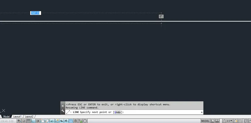
Take a line of length 2750mm using line tool in vertical direction
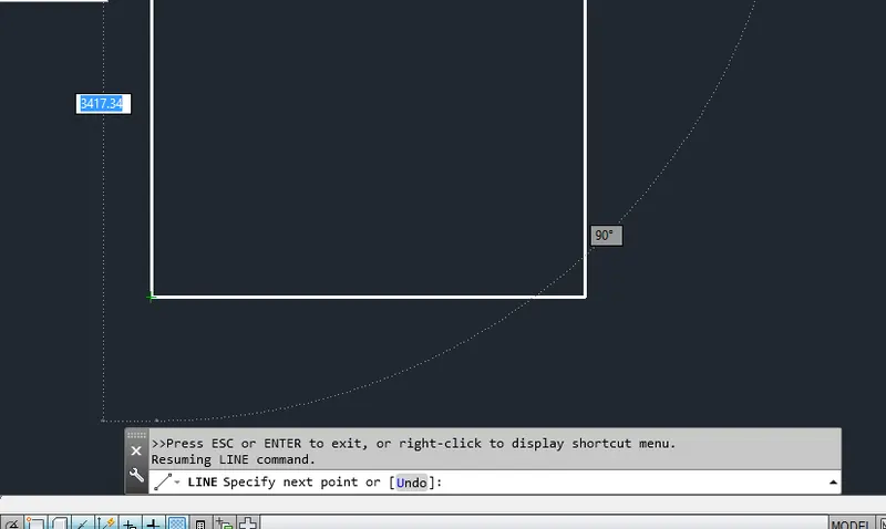
Divide the door segments by taking line of length 582.5mm using line tool
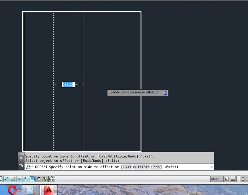
Now take a dimlinear command and measure the dimensions of the door
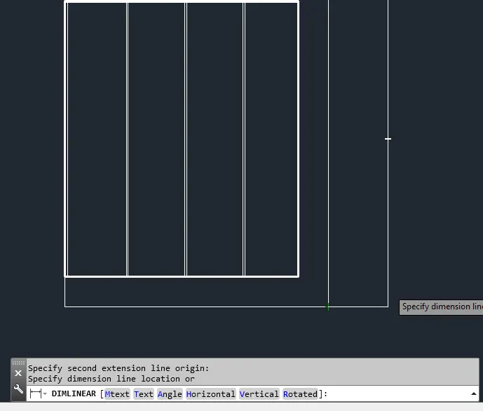
Go to block command and convert this door 2 to a block
Block definition dialogue box opens and give name as door2
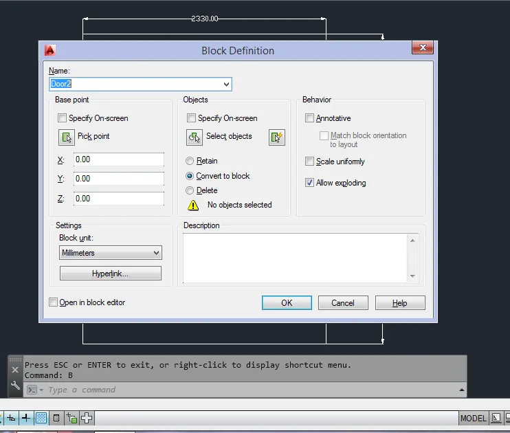
Select the objects to convert it into a block and press enter
And pick a point from the object and press enter and give ok
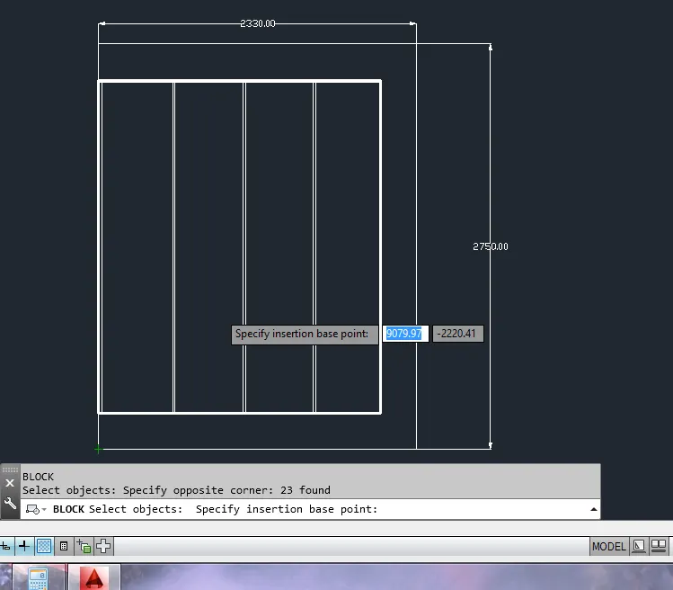
Result:
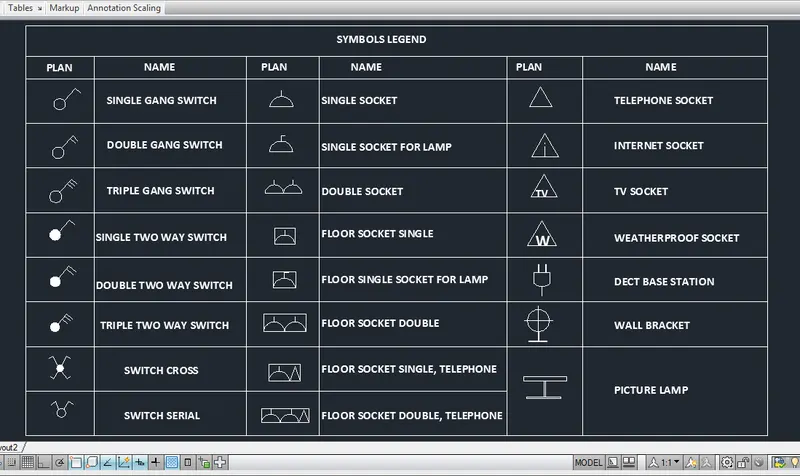
3) Aim: To create a given symbol with the name given in the legend by using Autocad2014
Procedure:
Go to start menu and select the autocad 2014 software click on that
And go to command tab and type Startup command
Give startup value as 1
Go to application menu and go to new option
Create new drawing dialogue box opens
Select units as decimal and precision 0.0 and press finish
And go to units and select units as decimal and precision 0.0 and insertion scale as millimeters
Then go to limits command and specify lower left corner as 500mm and upper right corner as 500mm
Go to circle command and draw a circle to draw single gang switch
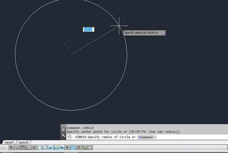
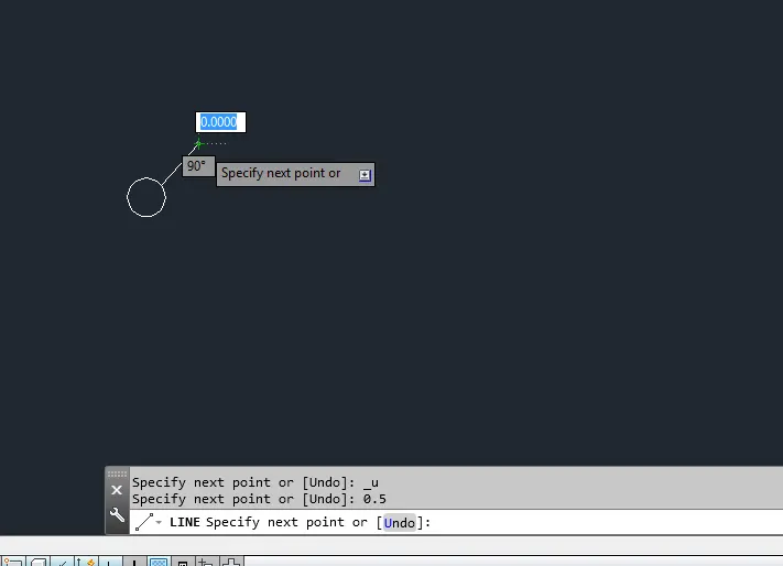
Take a line command and draw a line over the circle
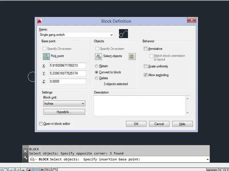
To convert this into a block go to block command and give name as Single gang switch
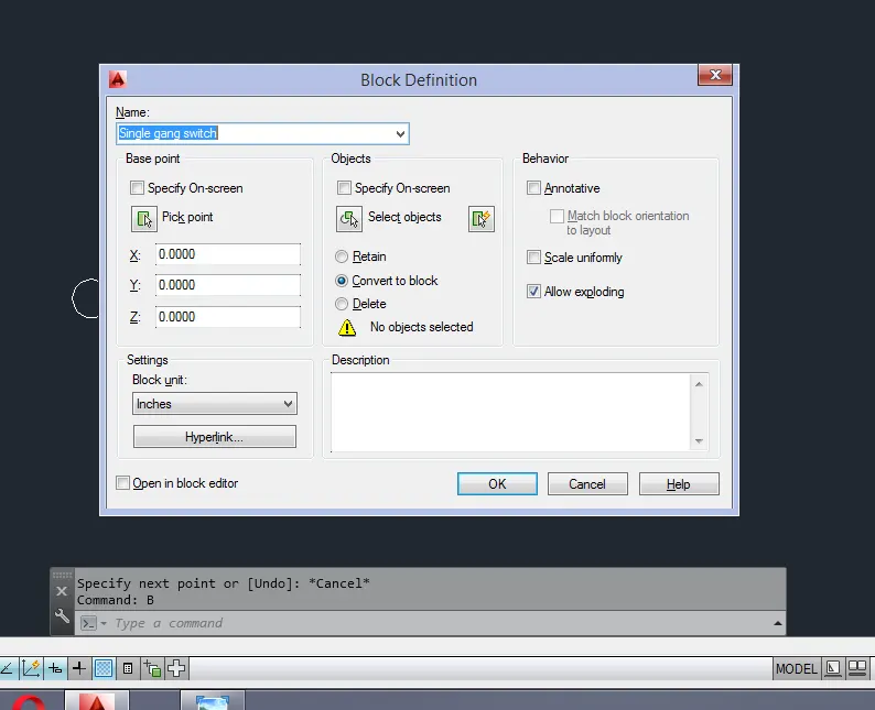
Select the objects using select object option and press enter
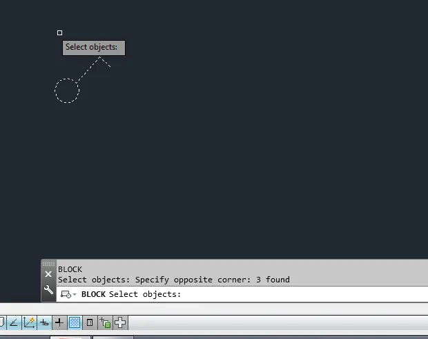
And pick a point using pick point option and press enter and press ok
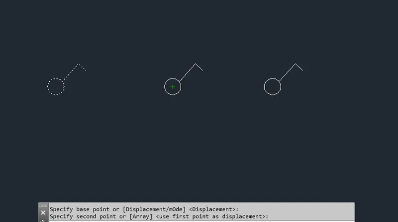
Copy the single gang switch into a multiple copies to create double gang switch and triple gang switch
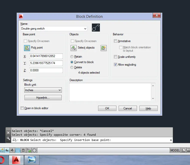
Create a block for the double gang switch using block command
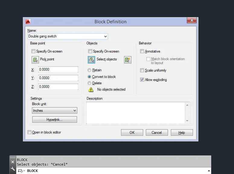
And select the objects using select object option
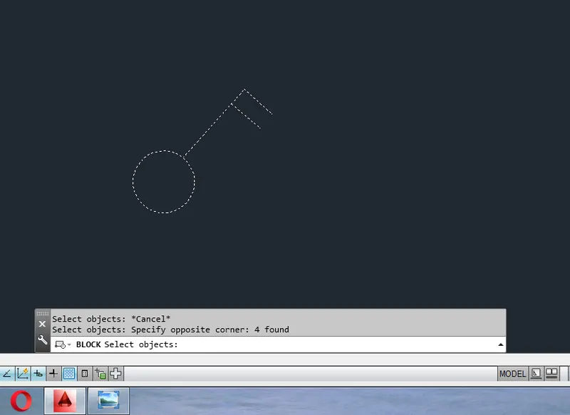
And pick a point using pick point option
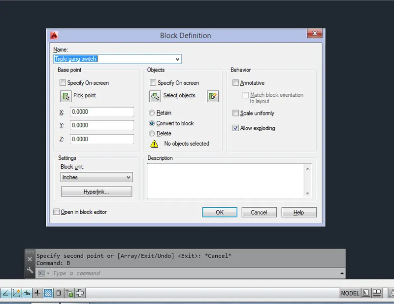
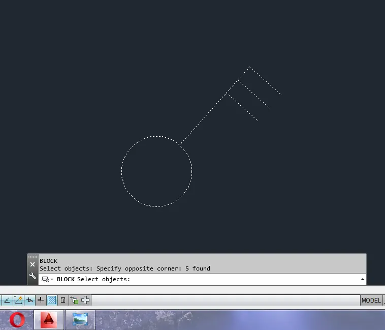
To convert triple gang switch in to a block go to block command and give a name
Select the objects by selecting select objects option
Select the point by using pick option
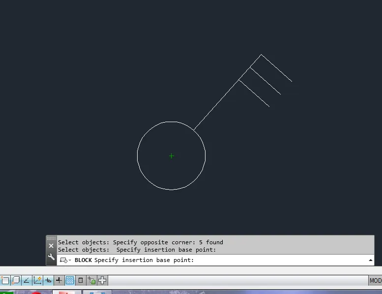
Hatch the circle using solid hatch command for the single two way switch by using hatch command
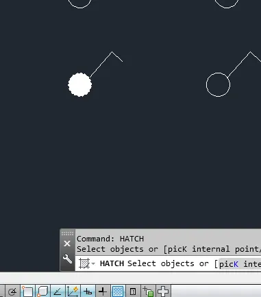
And also hatch the double two way switch using hatch command and solid hatch type
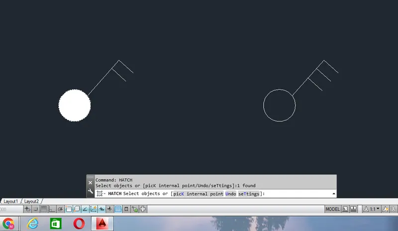
Hatch the triple two way switch using hatch command and solid hatch type
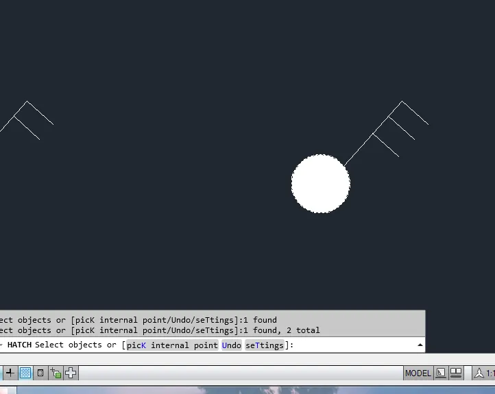
Go to block command and block definition dialogue box opens give a single two way switch as a name
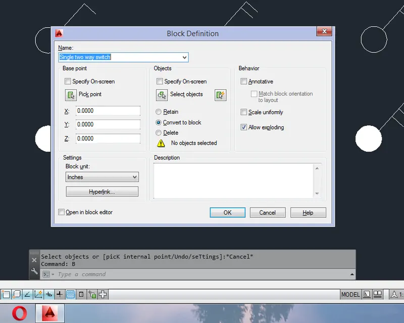
Select the objects to hatch by selecting select objects option
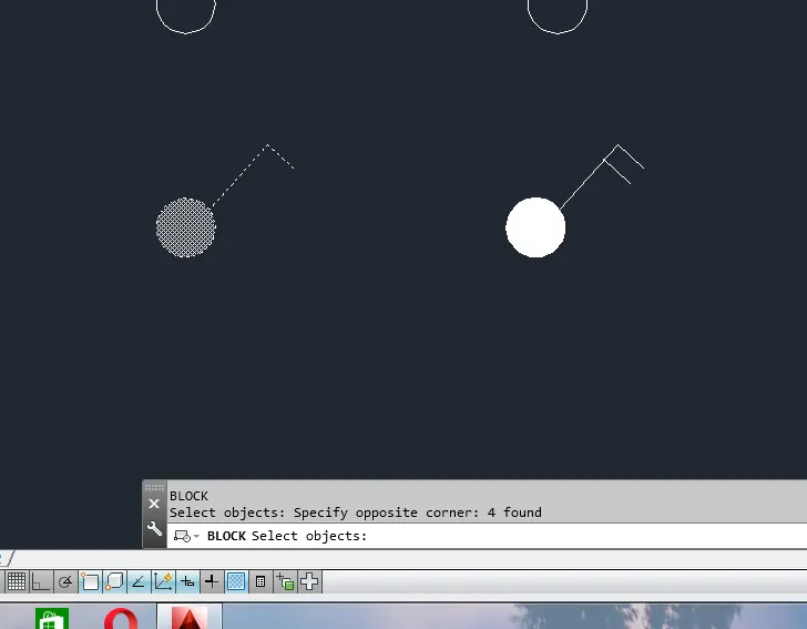
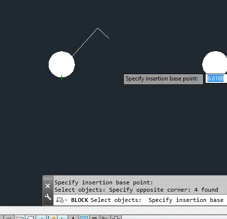
Pick the point using pick point option
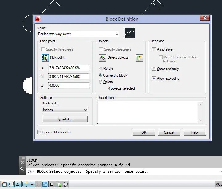
Go to block command to create block for the double two way switch using block tool
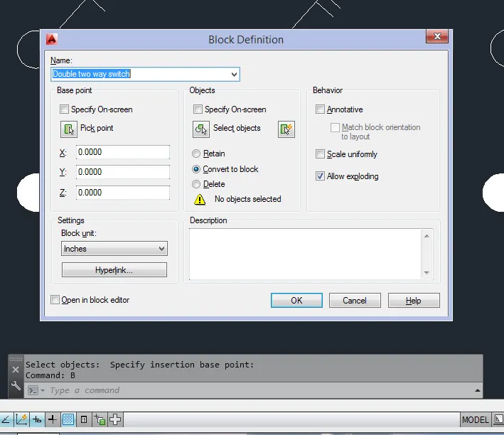
Select the objects by select object option
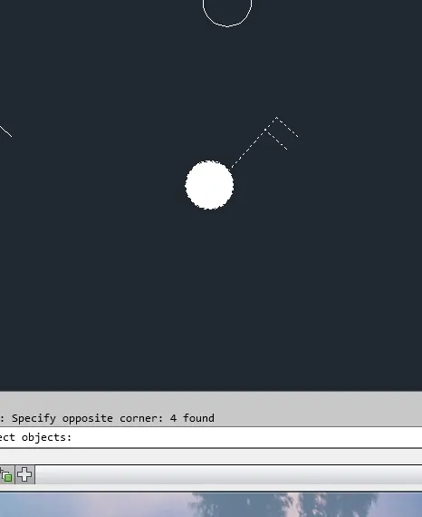
Pick the point of the object using pick point option
Create a block for the triple two way switch using block command
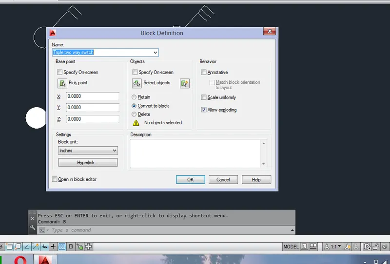
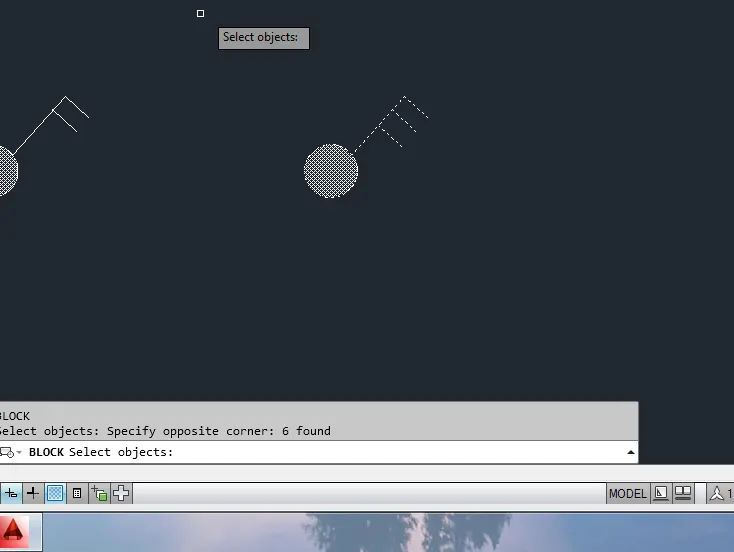
Select the objects using select objects option the object which is to be converted
Pick the point using pick point option of the block
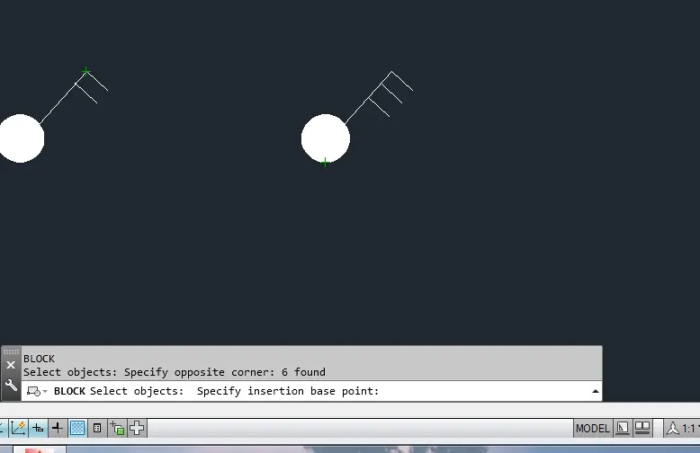
Create a switch cross by using circle and line
Go to block command and convert this object into block and give a name as switch cross
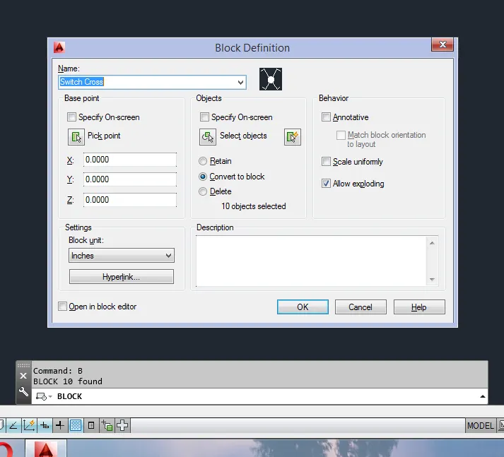
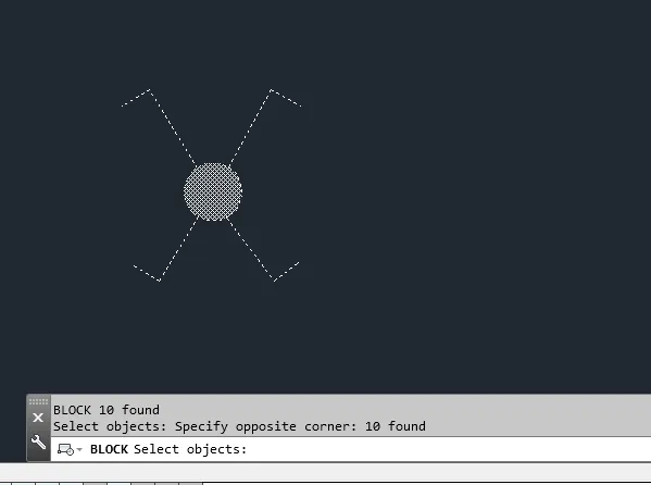
Select the object using select object option
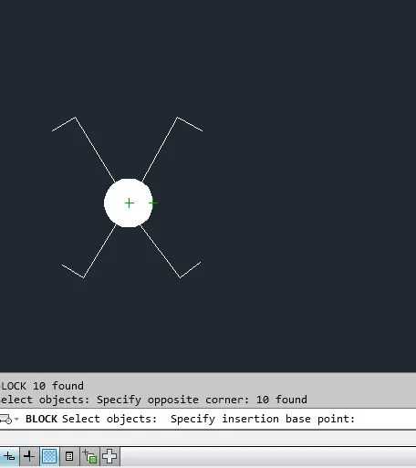
And pick the point from the object using pick point option
Create the switch serial by using circle and line command
Go to block command and give the block name as switch serial
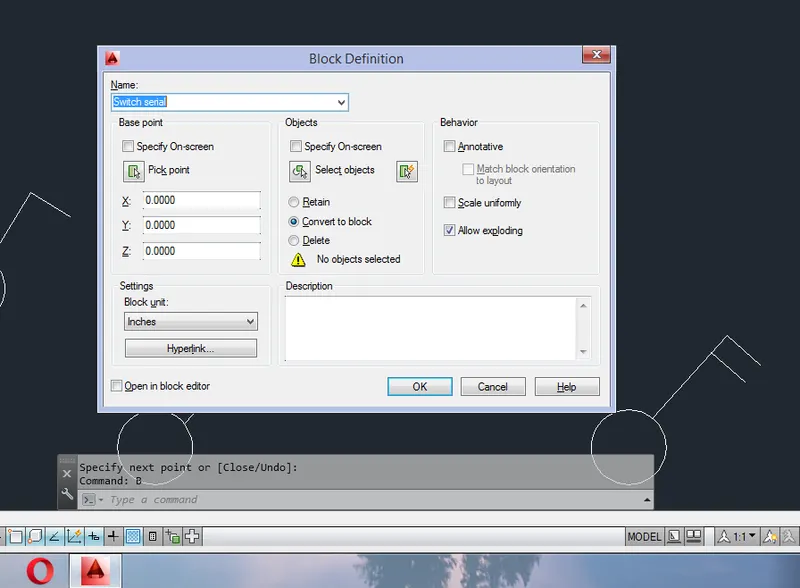
Select the objects by using select object option
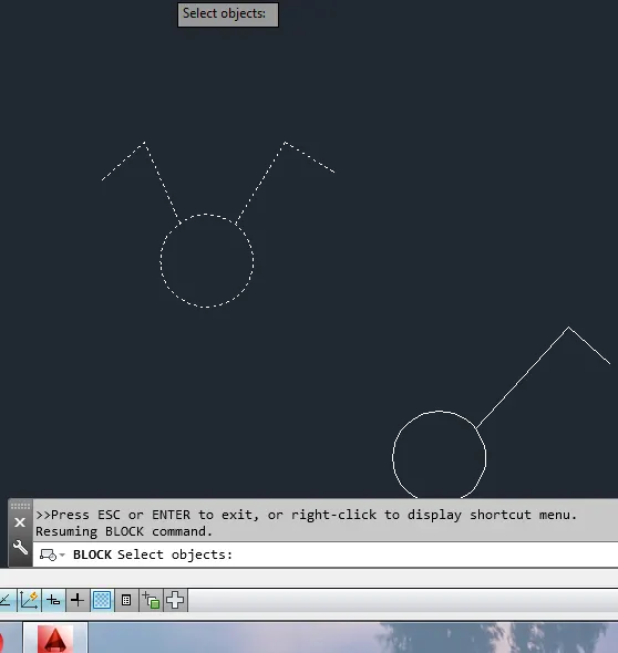
Pick the objects by using pick point option
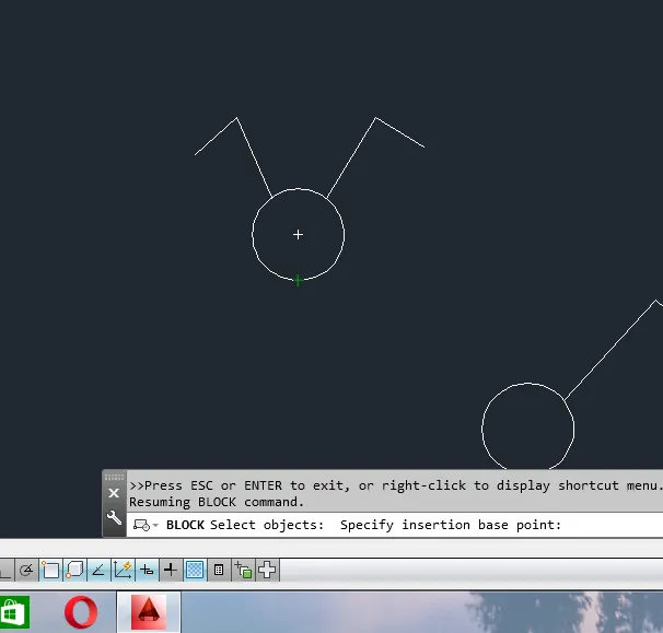
Create the single socket by using arc and line command
Go to block and convert the object into a block by giving the single socket name
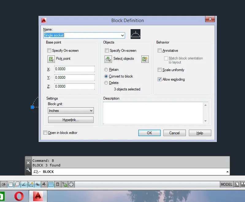
And select the objects by giving select object option
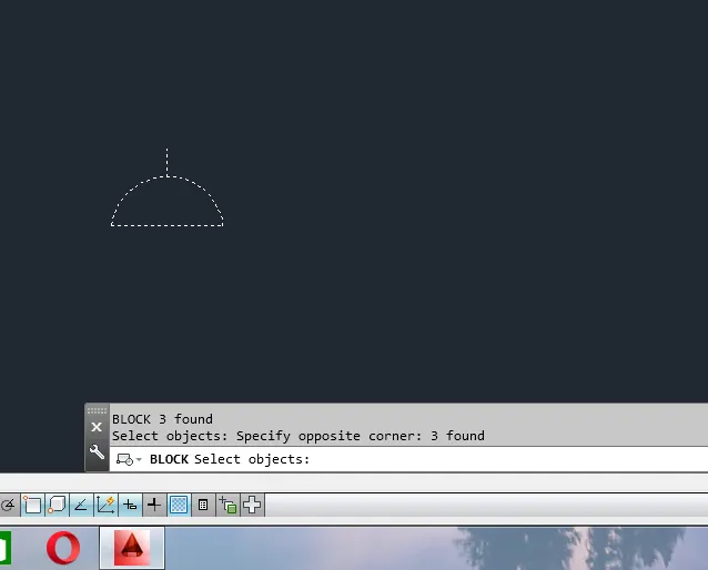
And pick the point using pick point option
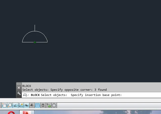
Create the single socket for lamp using arc and line
Go to block command and create the block for this object and give the name as single socket for lamp
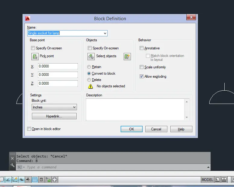
And select the objects by using select object option
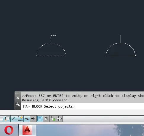
And pick the point using pick point option
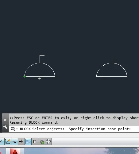
Create the double socket switch by using arc and line command
Go to block command and create this object into a block and give the name as double socket
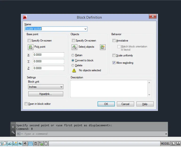
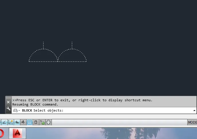
Select the object by using select object option
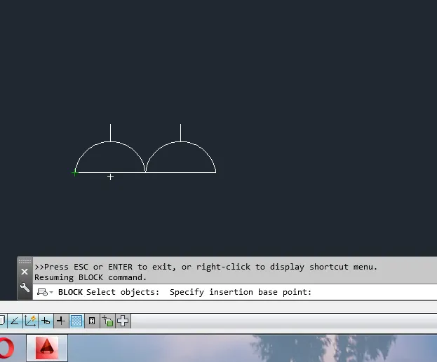
Pick the points by using pick point option
To create a floor socket single use arc and line and rectangle command
Go to block command and convert the object into block using block tool and give the name as floor socket single
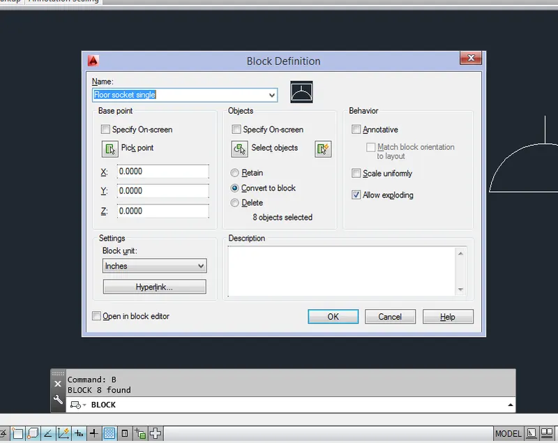
Select the objects by using select object option
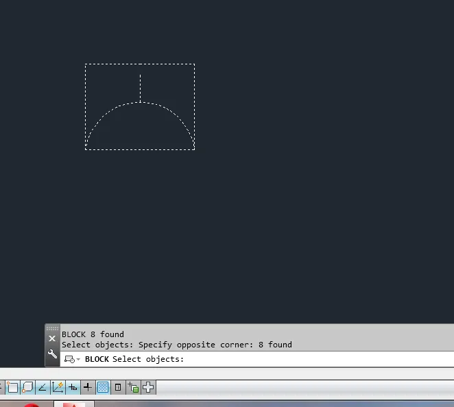
Pick the point using pick point option
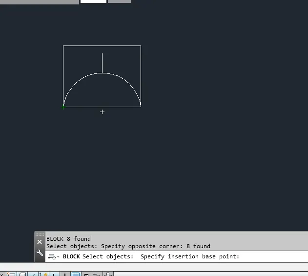
To create a floor single socket for lamp use arc, line and rectangle tool
Go to block and create a block using block command and give the name as floor single socket for lamp
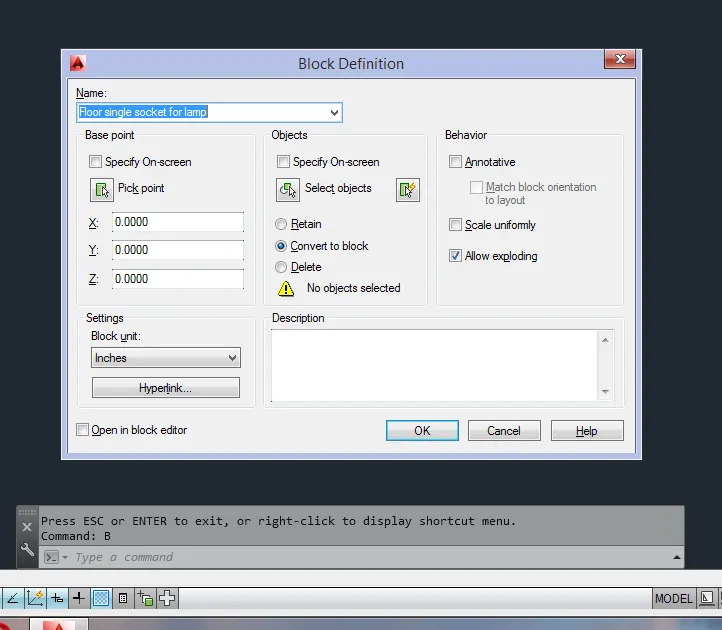
Select the objects by using select object option
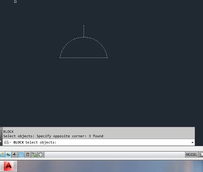
Pick the point using pick point option
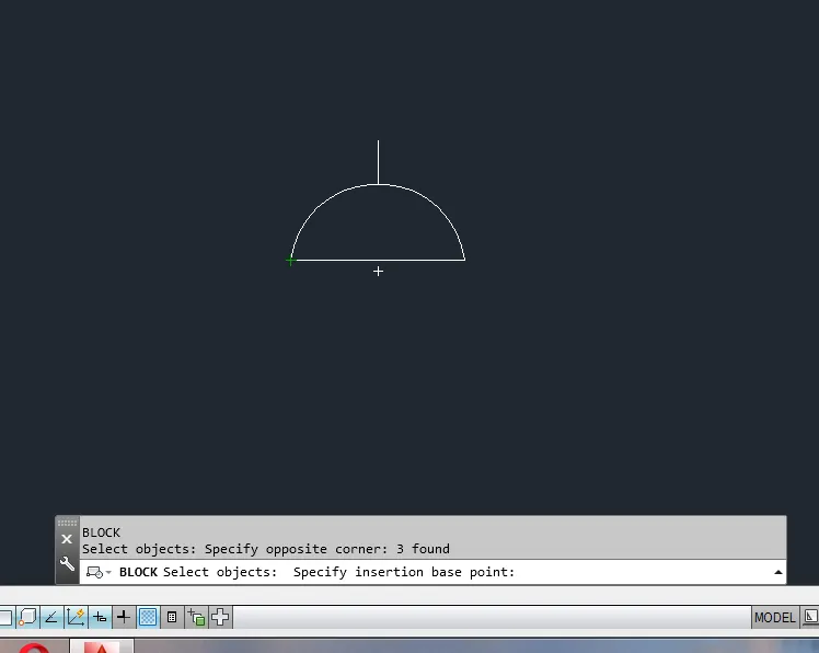
Create the floor single socket for lamp using arc line command
Go to block command and create a block and give a name as floor single socket for lamp
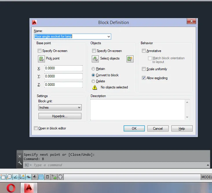
And select the objects using select object option
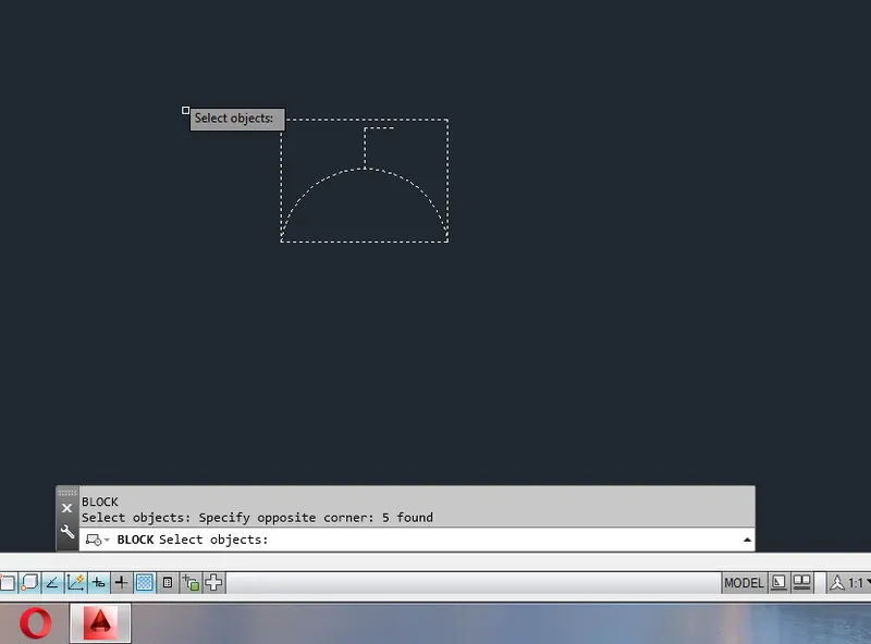
And pick the point using pick point option
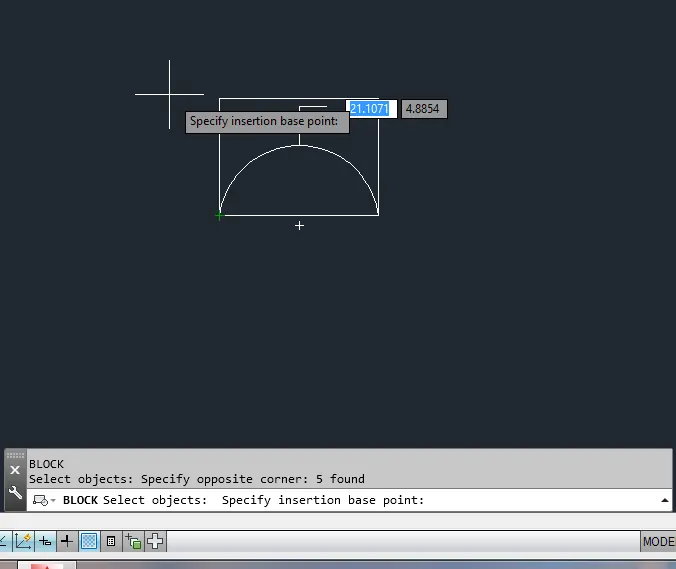
To create the floor socket double use arc and line tool for the creation
Go to block command and create a block using block tool and give the name as floor socket double
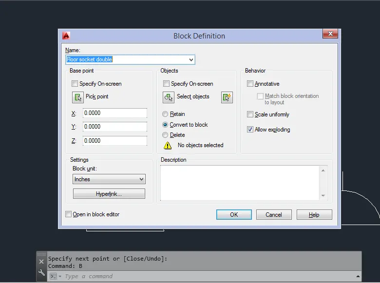
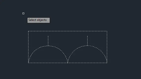
Select the objects using select object option
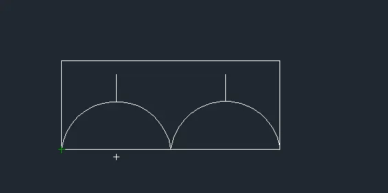
Pick the points using pick point option
To create floor socket single, telephone use triangle, line and arc command
Go to block command and create a block using block command and give the name as floor socket single, telephone
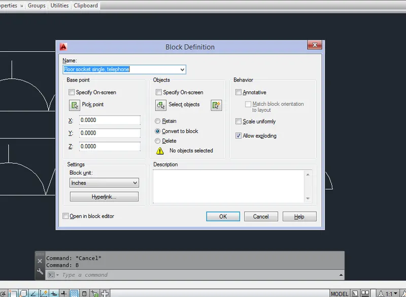
Select the objects using select objects option
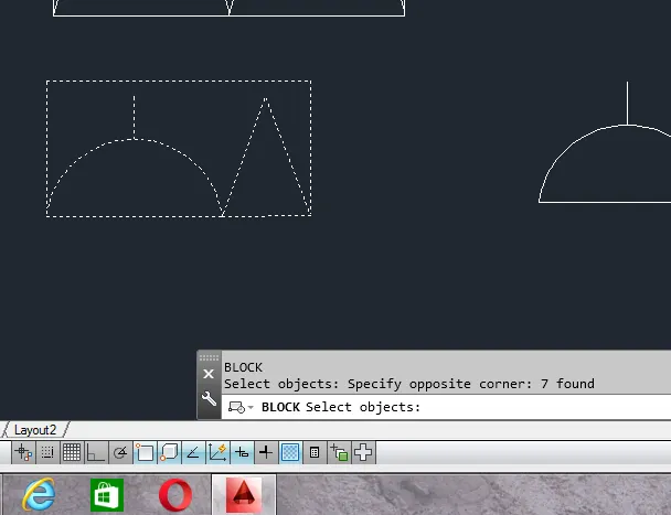
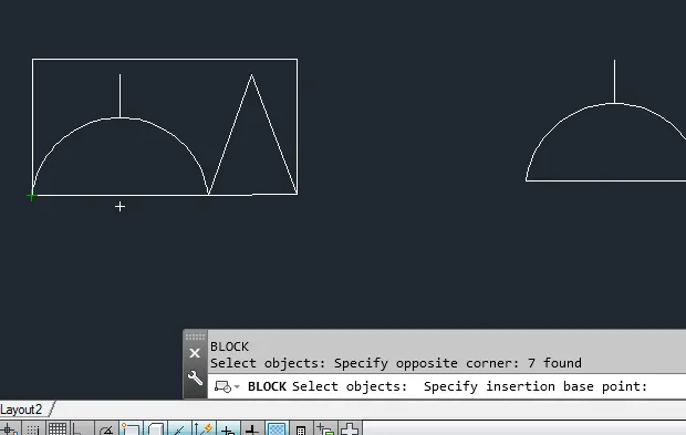
Pick the point using pick point option
To create floor socket double, telephone use arc line and triangle tool
Go to block command and create a block using block tool and give the name as floor socket double telephone
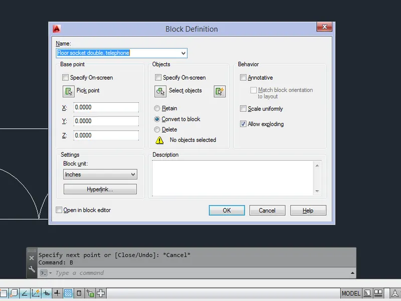
Select the objects by using select object option
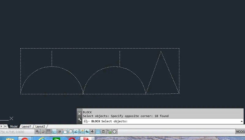
Pick the point using pick point option
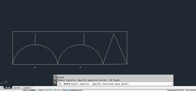
To create a telephone socket use triangle as a command
Go to block and convert this into block and give the name as telephone socket
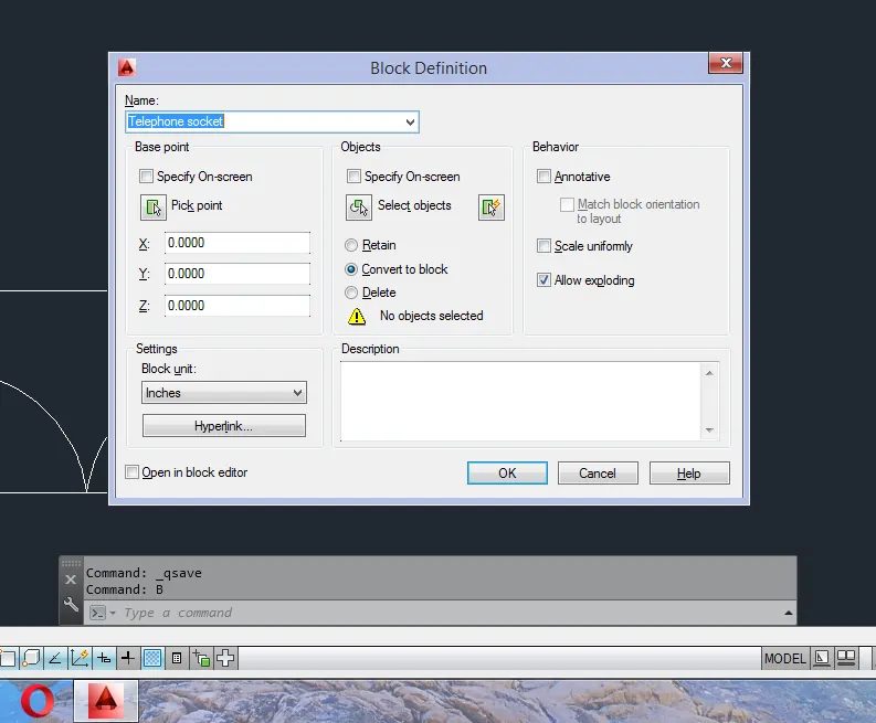
Select the objects by giving select object option
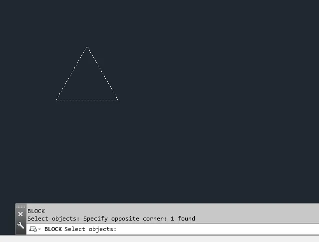
Pick the points using pick point option
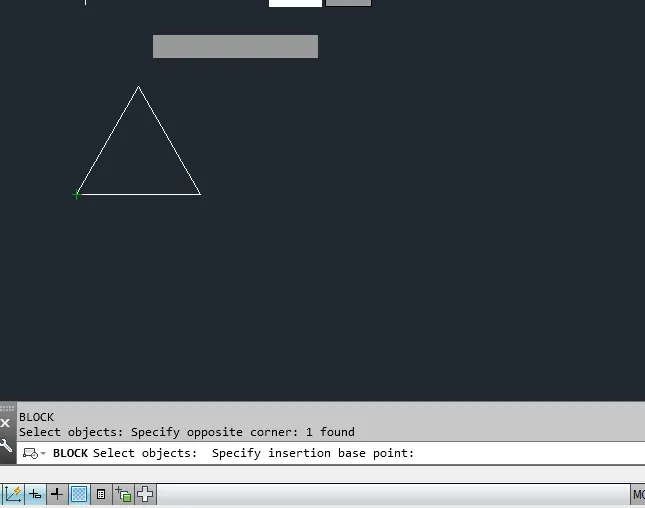
To create the internet socket use polygon and line command
Go to block command and create this as a block using block command and give the name as internet socket
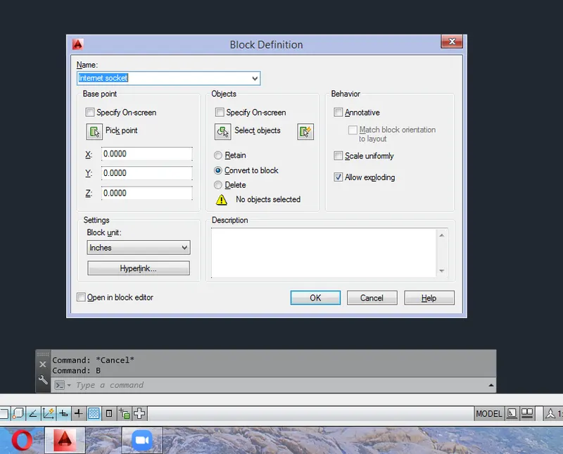
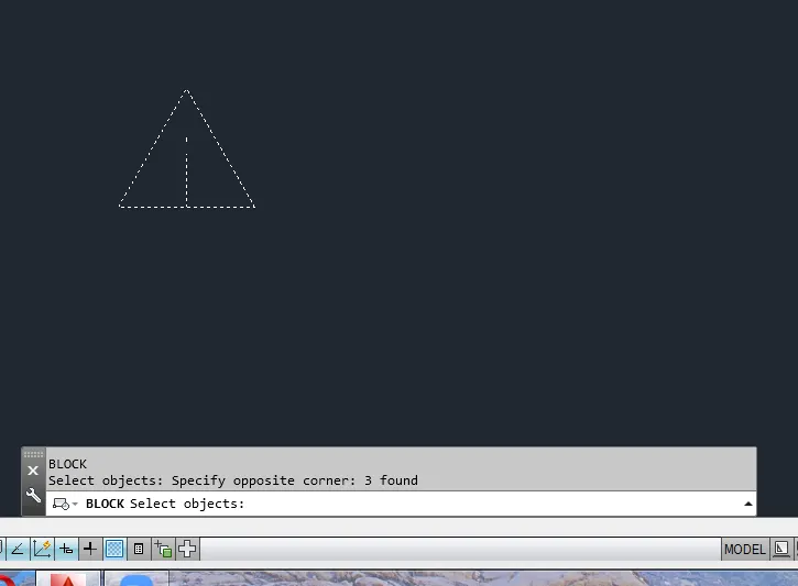
Select the objects by using select object option
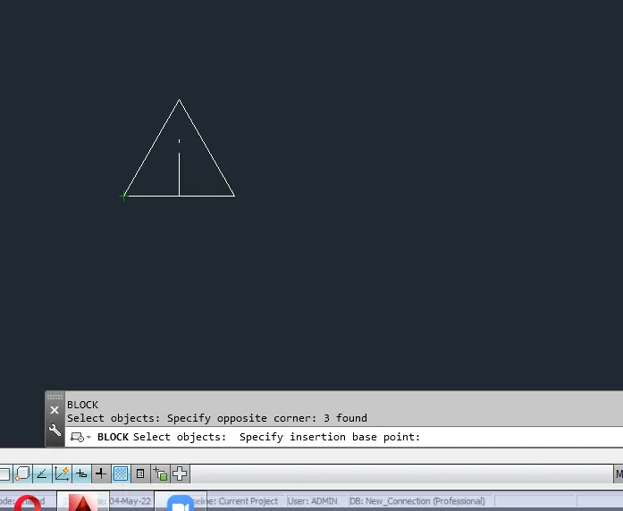
Pick the points using pick point option
To create TV socket use polygon and text option
Go to block command and convert this into a block and give the name as TV socket
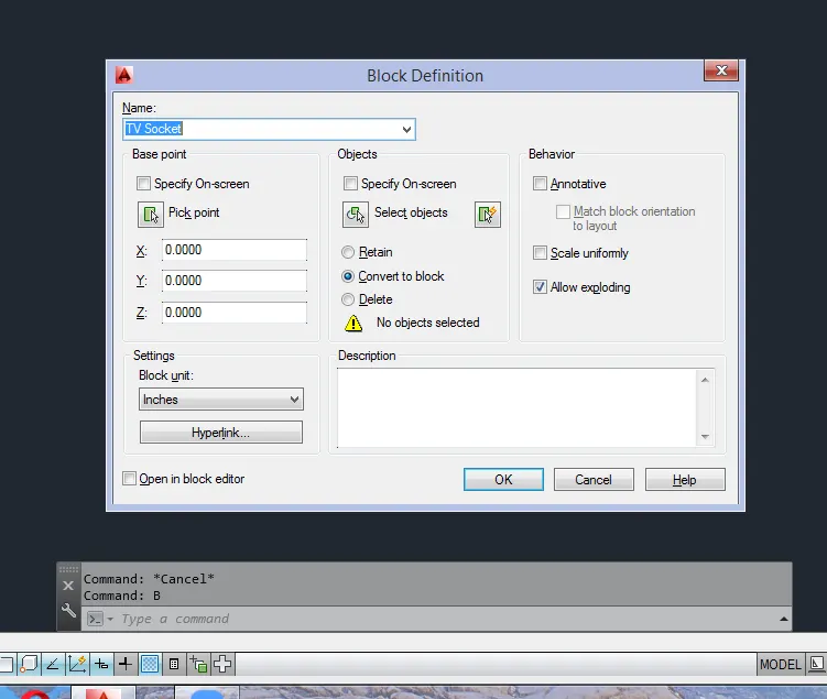
Select the objects using select object command
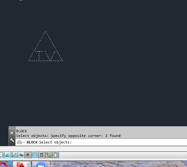
Pick the points using pick point option
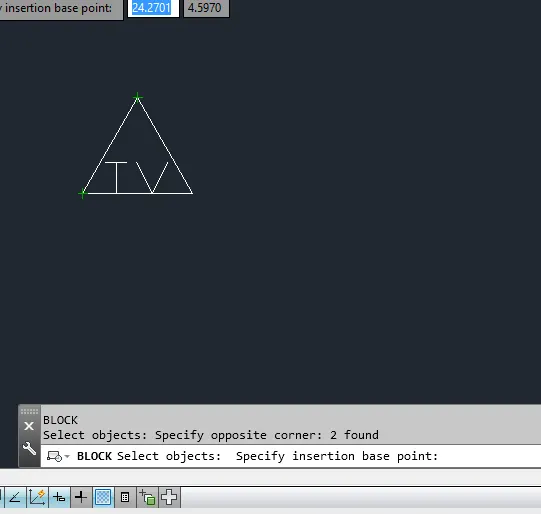
To create weatherproof socket use polygon and text command
Go to block command and create the block using block command tool and give the name as weatherproof socket
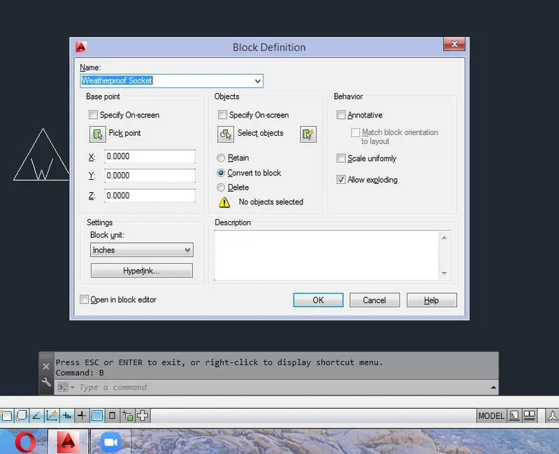
Select the objects by using select object option
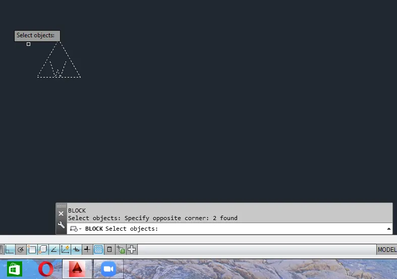
Pick the points using pick point option
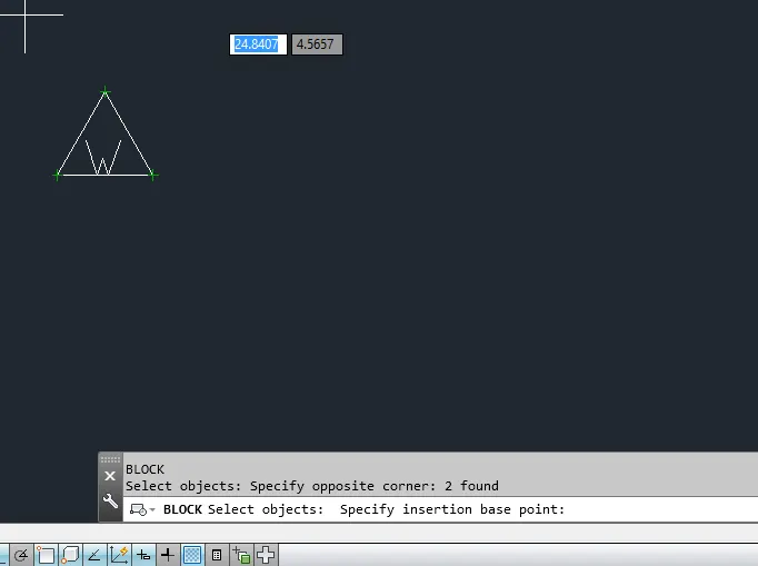
To create dect base station use line command
Go to block command and create the block using block tool and give the name as dect base station
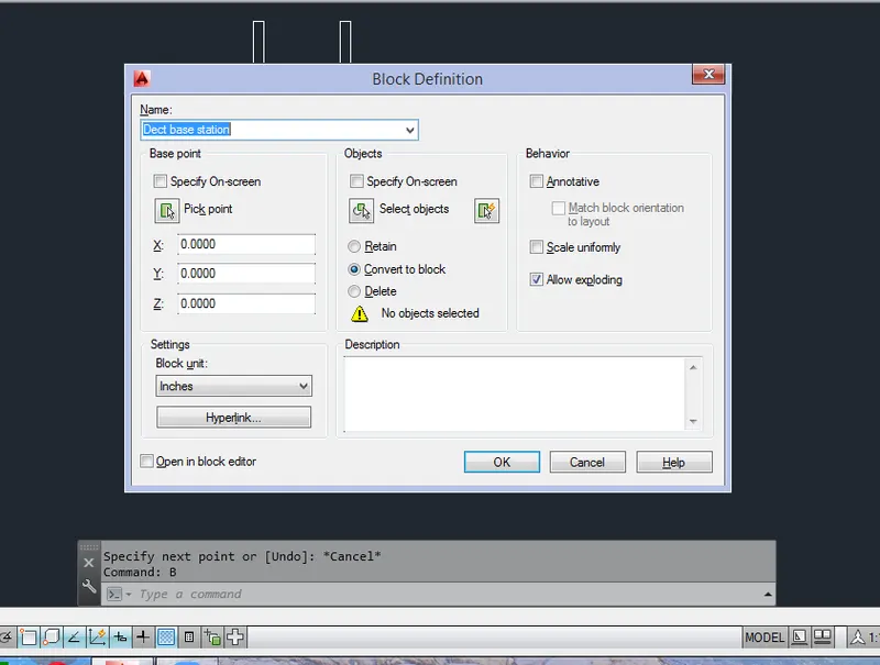
Select the objects using select object option
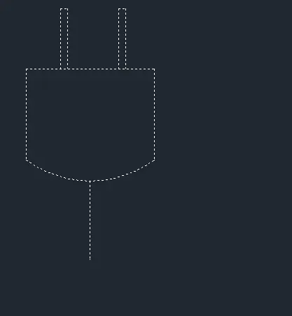
Pick the point using pick point option
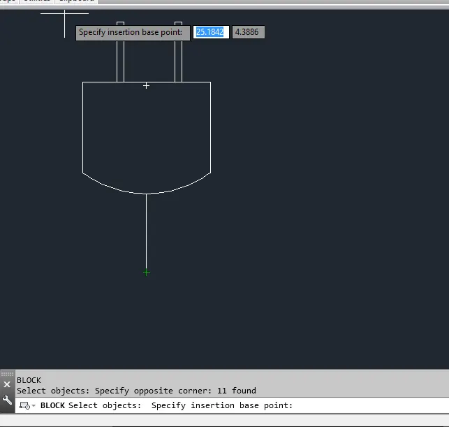
To create the wall bracket use circle and line tool
Go to block command and create a block and give the name as Wall bracket
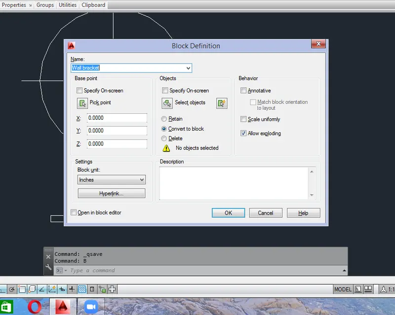
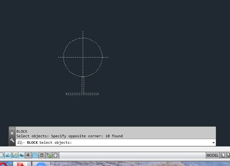
Select the objects by using selecting select object option
Pick the point using pick point option
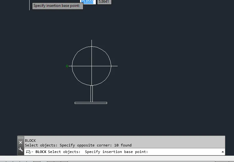
To create Picture lamp use line tool
Go to block command and give the name as picture lamp
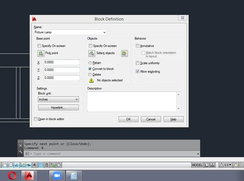
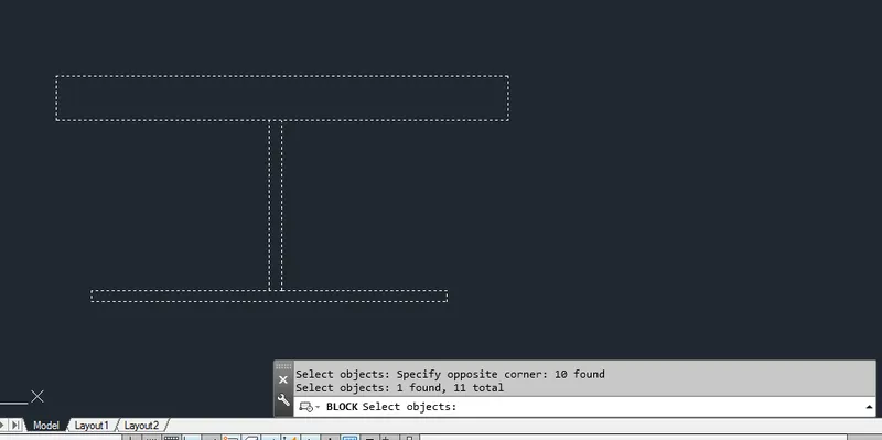
Select the objects using select object option
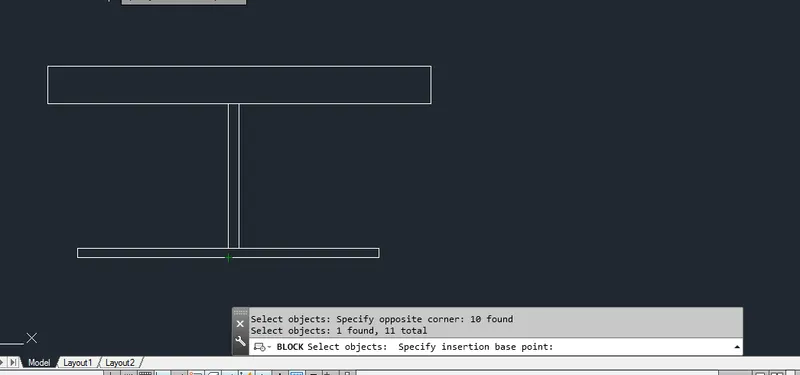
Pick the points using pick option
Then go to table command and insert the table by selecting suitable columns and rows numbers
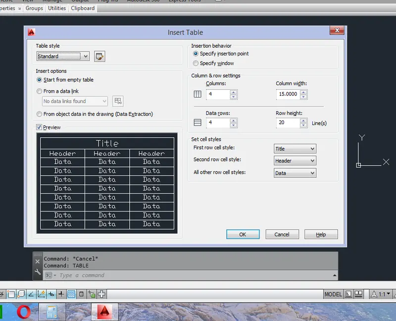
Specify insertion point on the screen
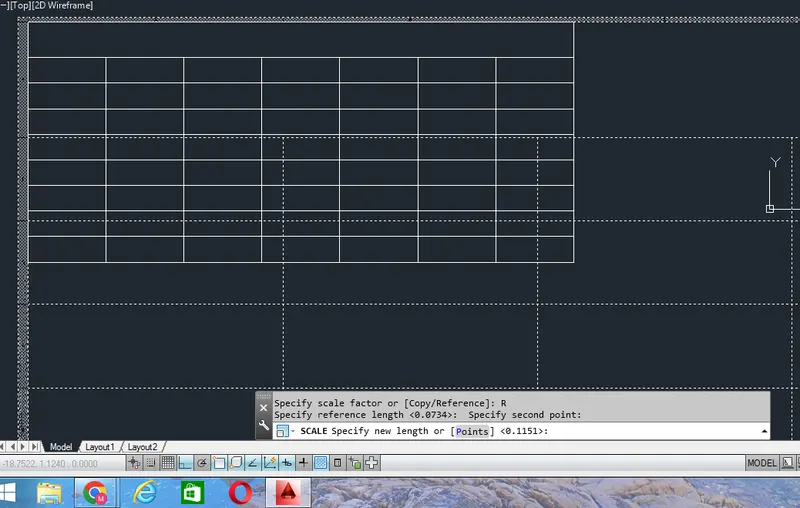
Insert the text inside a table using text command
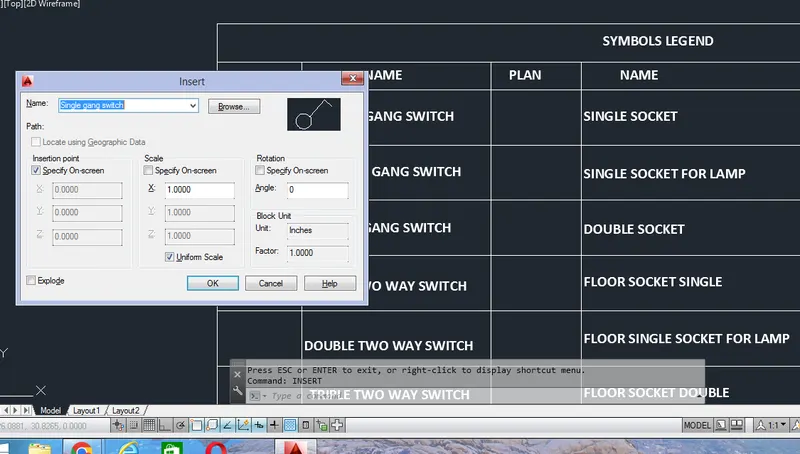
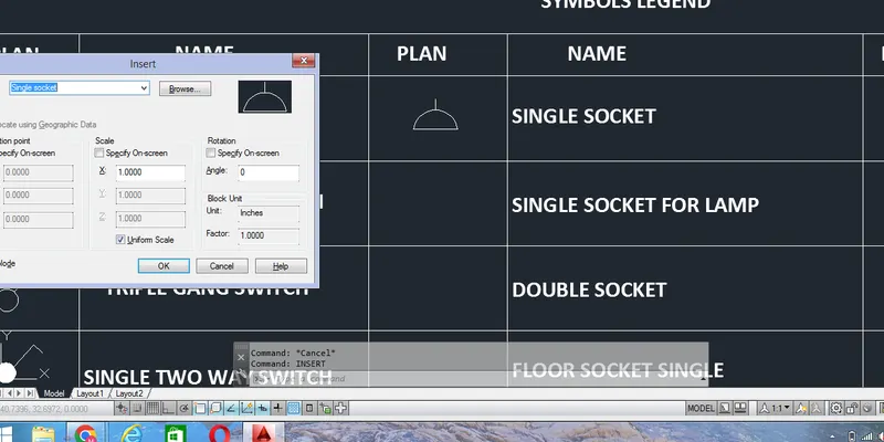
Now after adding the text inside the table insert the created block using insert option
Result:
4) Aim:
Go to start menu and select the autocad 2014 software click on that
And go to command tab and type Startup command
Give startup value as 1
Go to application menu and go to new option
Create new drawing dialogue box opens
Select units as engineering and precision as 0'00" and press finish
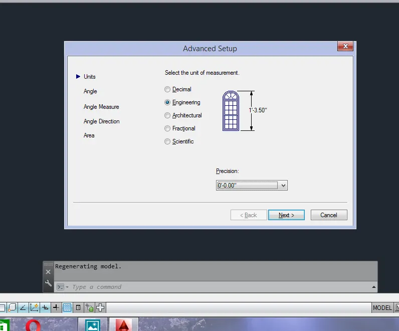
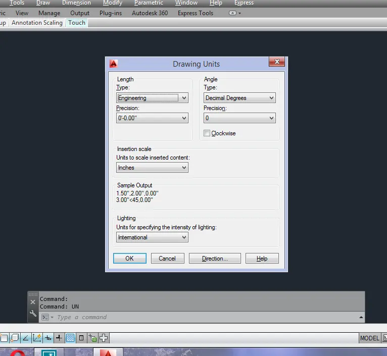
And go to units and select units as engineering and precision 0'00" and insertion scale as inches
Then go to limits command and specify lower left corner as 500' and upper right corner as 500'
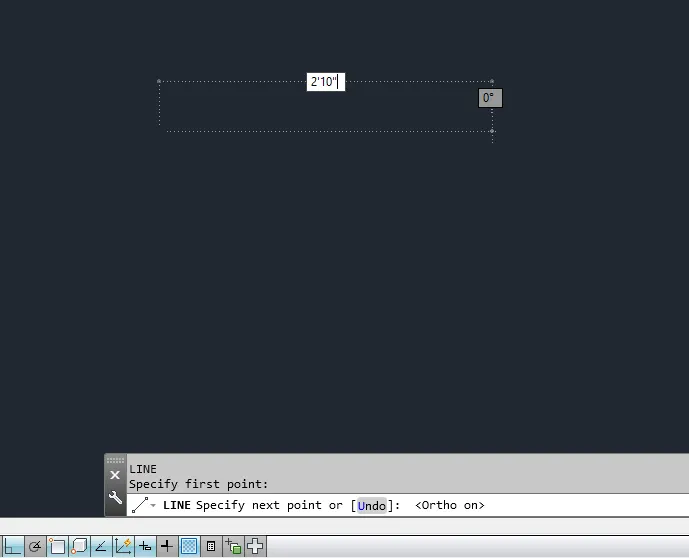
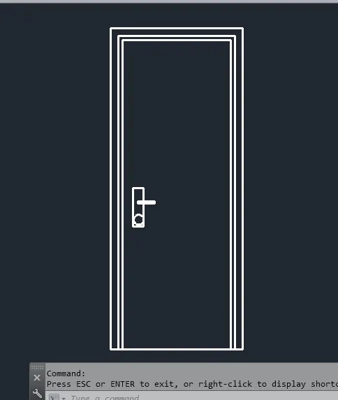
Then go to line command and draw a line of length 2'10" in horizontal direction
Again go to line command and draw a line of length 6'11" vertically downwards
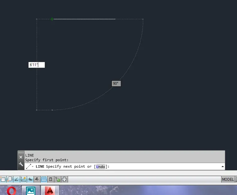
Take a offset of 2'' inside the door frame using offset tool
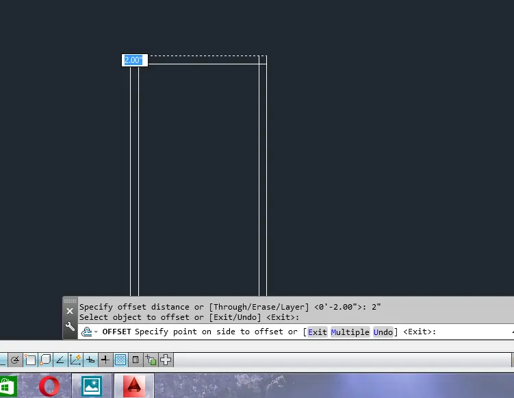
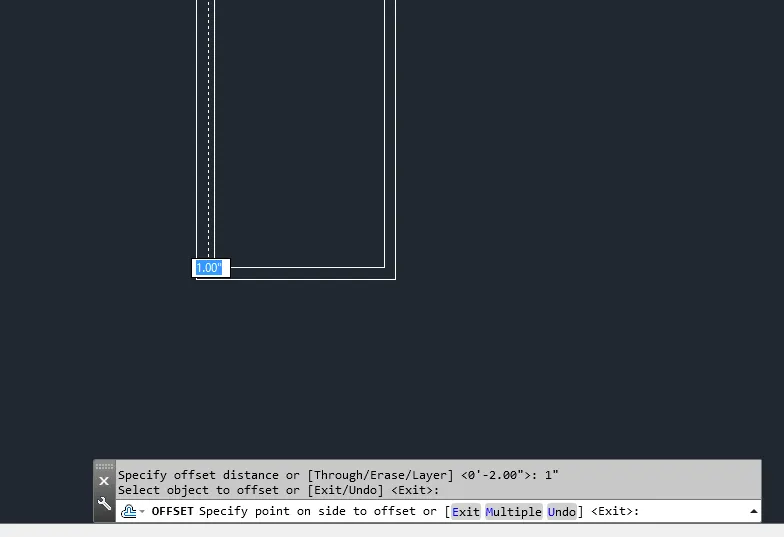
Take a offset of length 1" using offset tool inside the taken offset line
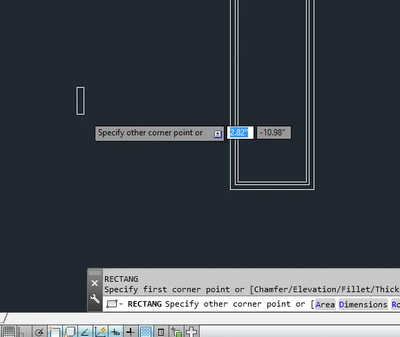
Take a rectangle command and create a small lock for the created door
Result
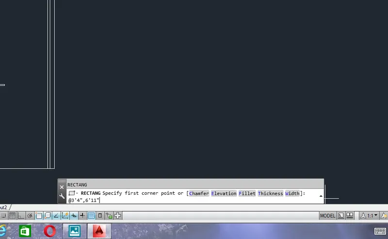
b) Create a rectangle of size 3'4" as a width and 6'11" as a length using rectangle tool
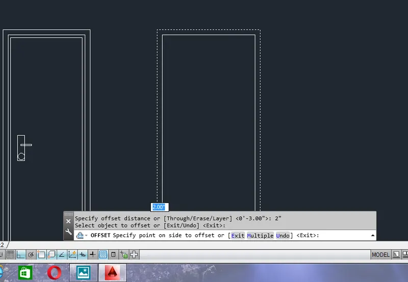
Take a offset of 2" inside the rectangle using offset command
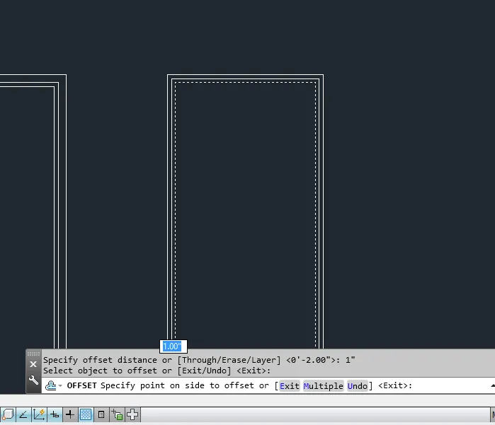
Take a offset of 1" using offset tool inside the created offset rectangle
Create a two rectangle using rectangle command and draw a two rectangle inside the door to draw a panel of a door
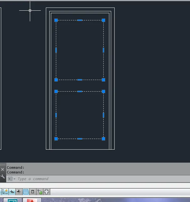
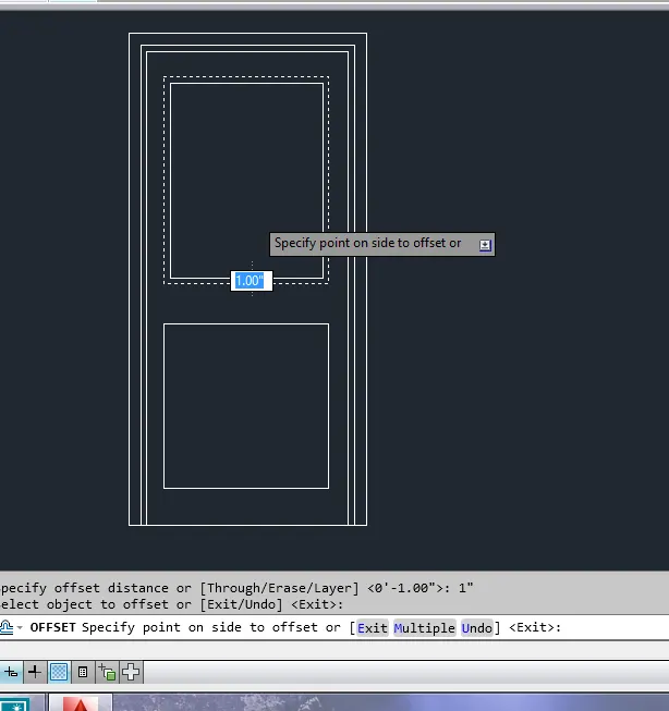
Take a offset of length 1" inside the rectangle using offset tool
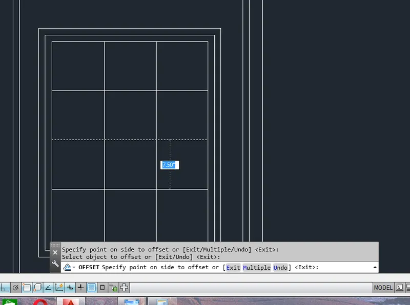
Divide the segments into 3X4 equal parts
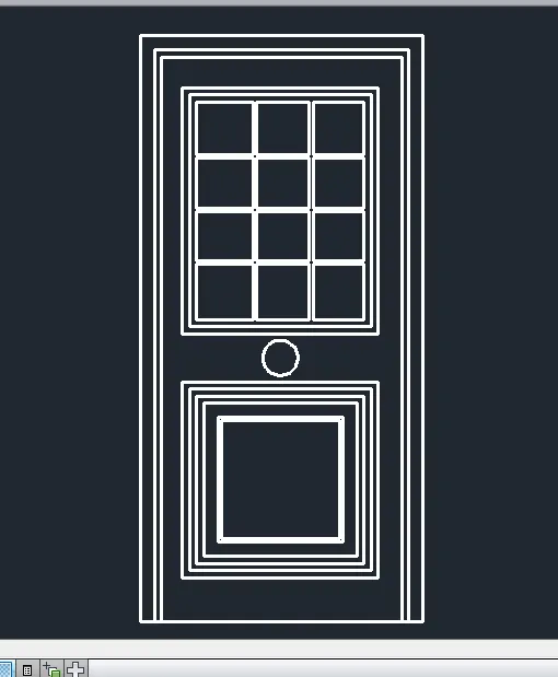
Finally the door d2 is created
Result
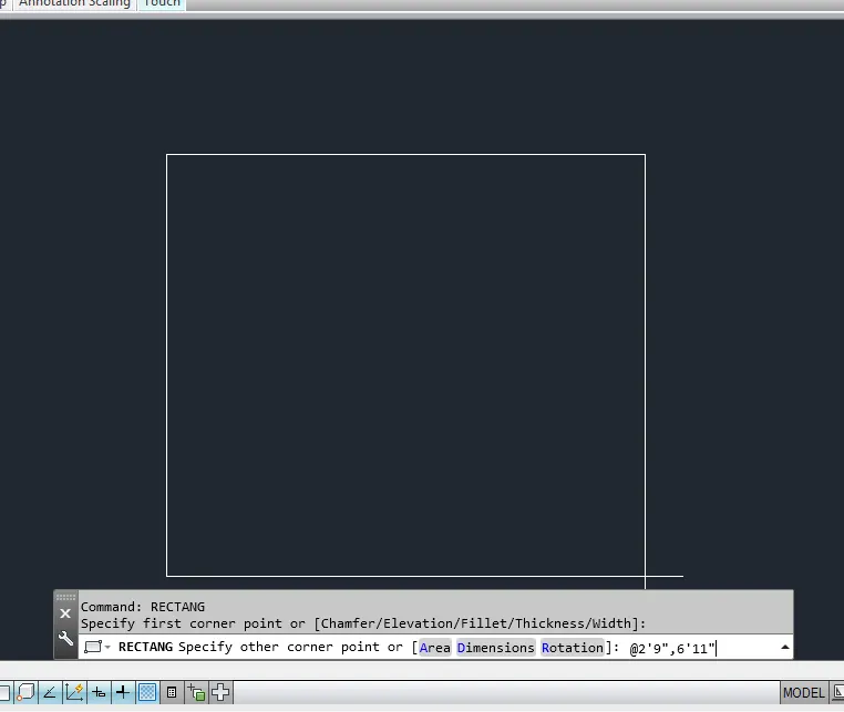
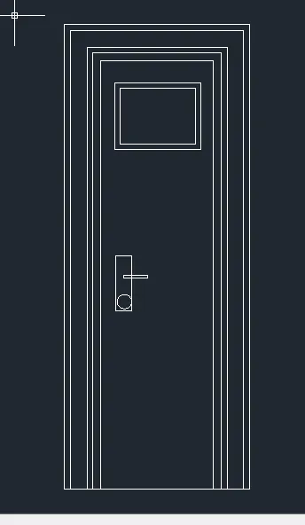
c) To create a door d3 use rectangle command and draw a 2'9" as a width and 6'11" as a length of the rectangle
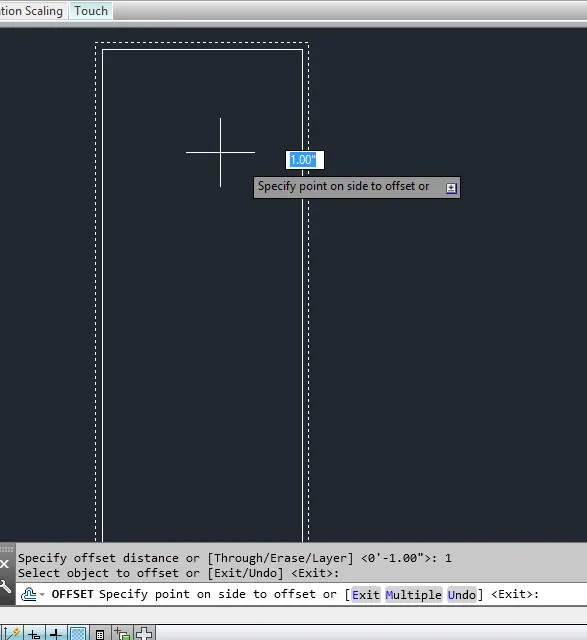
Take a offset of length 1" inside the door d3 using offset tool
 .
.
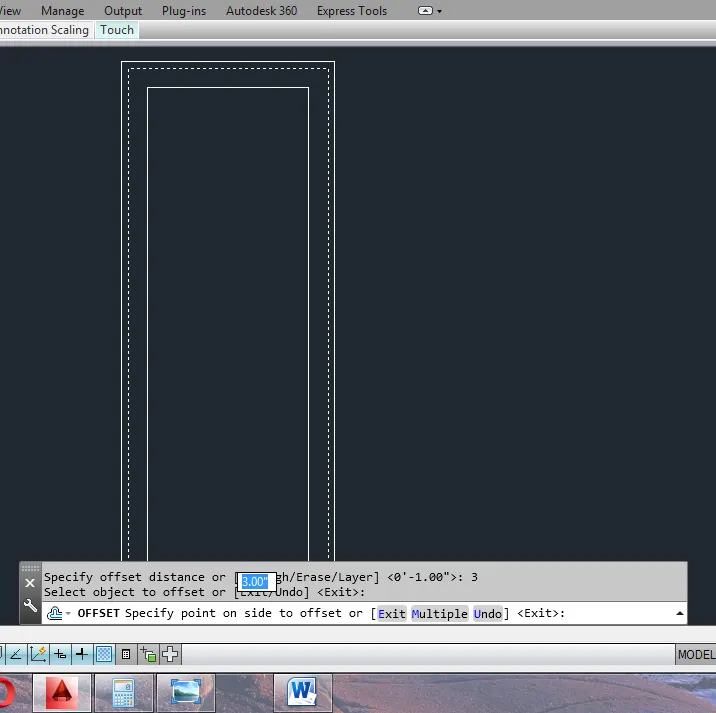
Again take a offset of length 3” using offset tool inside the rectangle
Result:
d) Create a door d4 using line command and draw a line of length 6'11" vertically downwards using line tool
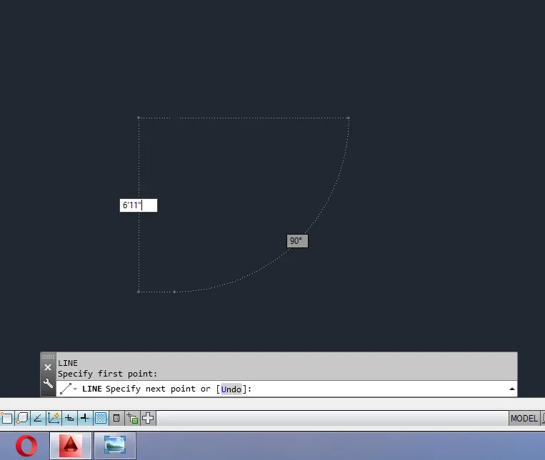
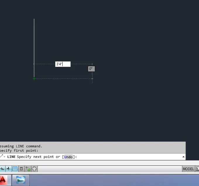
And draw a line of width 3'4" using line tool
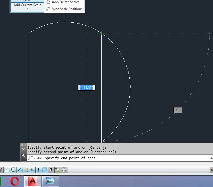
Take a arc command and create a door d3 using arc command
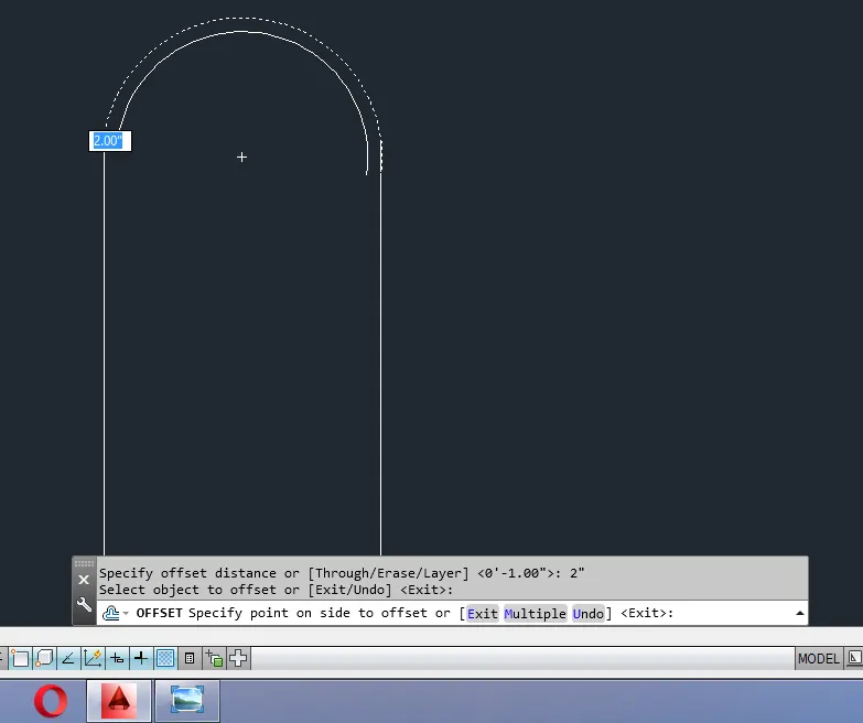
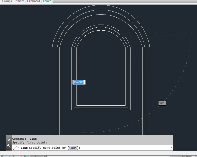
Take a offset of 2" inwards using offset tool
Take a offset of 1" using offset tool inside the door d4
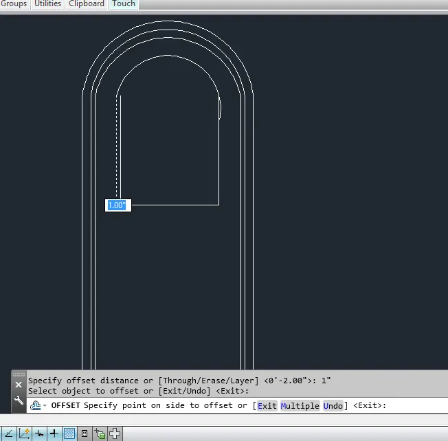
Draw a line using line tool
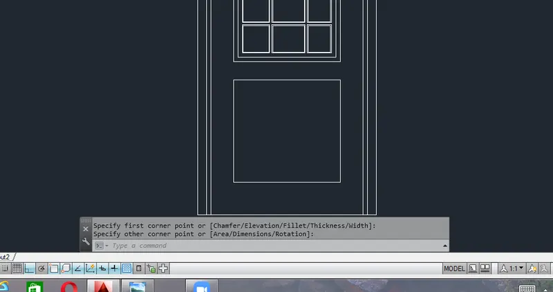
Create a rectangle inside this using rectangle command
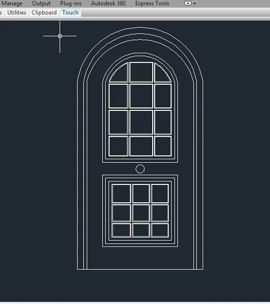
Result:
e) Copy the door d4 to create a door d5 by using copy command
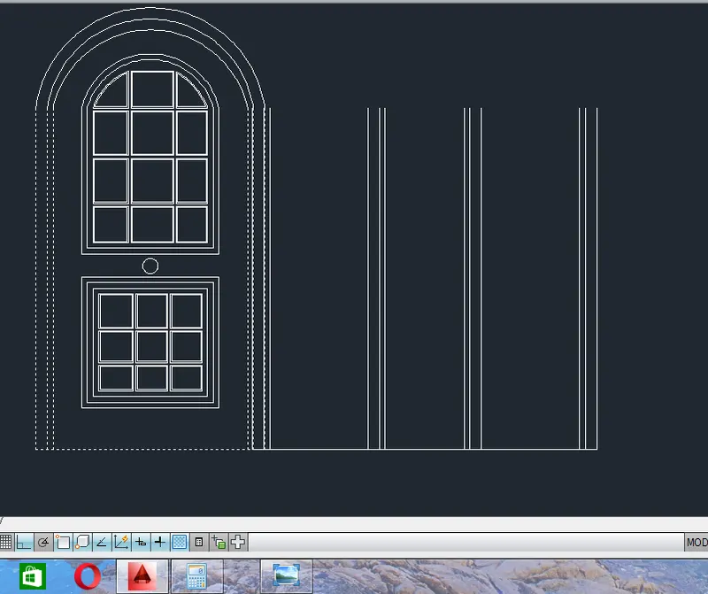
And also copy those objects which were indicated as panel of a door
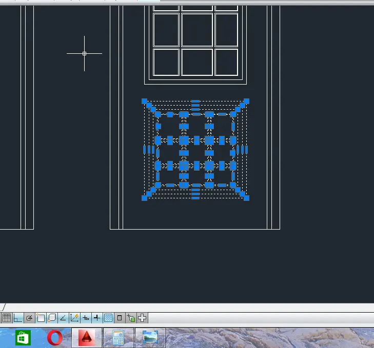
Result:
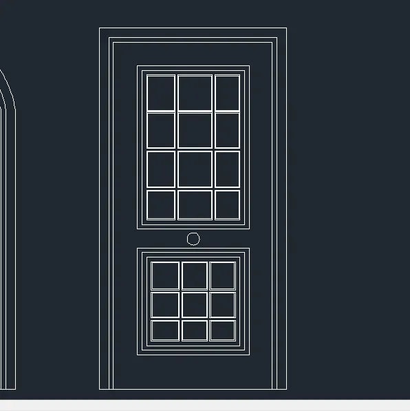
f) For the door d6 also copy the objects from the door 4 using copy tool
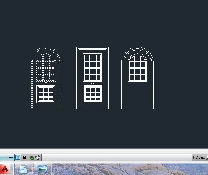
Copy the panel of a door using copy tool
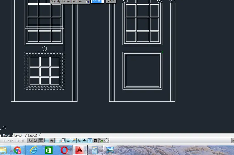
Take a offset of length 2" using offset command inside the panel
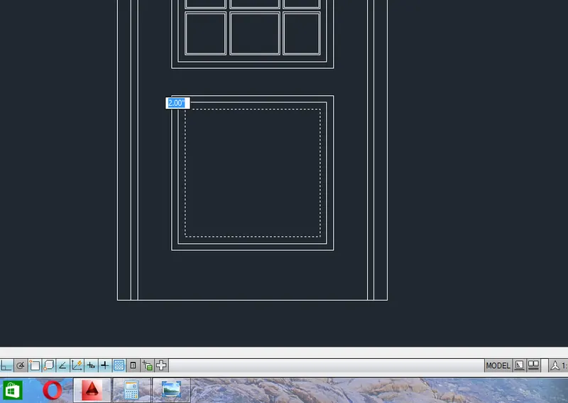
Again take a 0.5" inches of offset using offset command inside the panel of a door d6
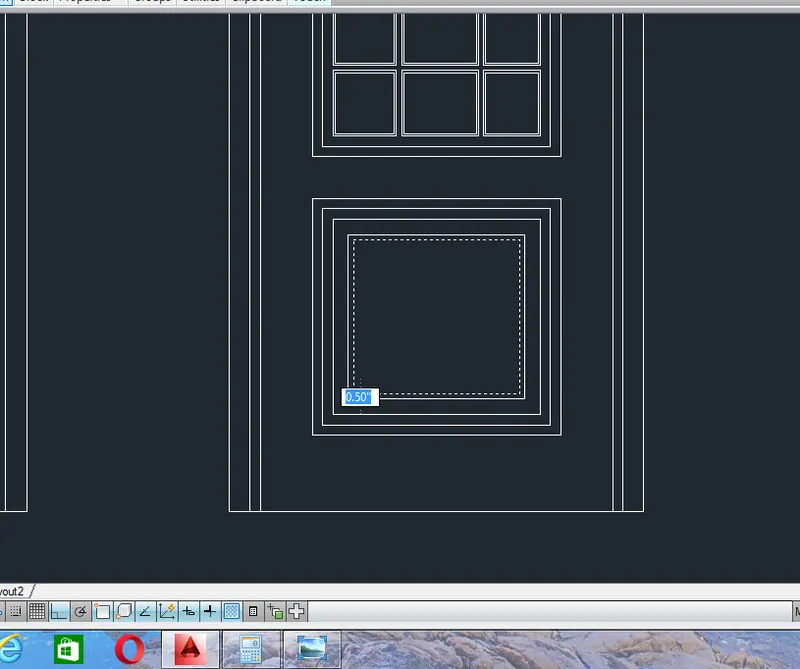
Result:
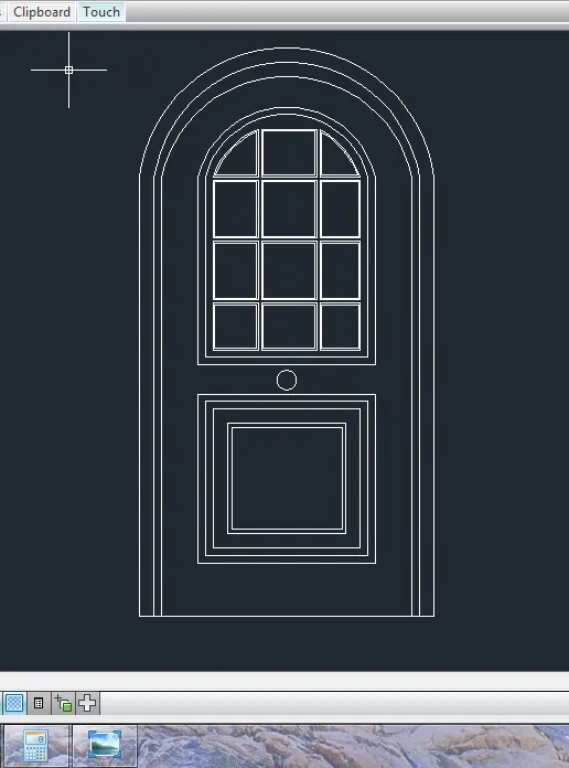
In order to create a block go to block command and save the block in the name of TYPE
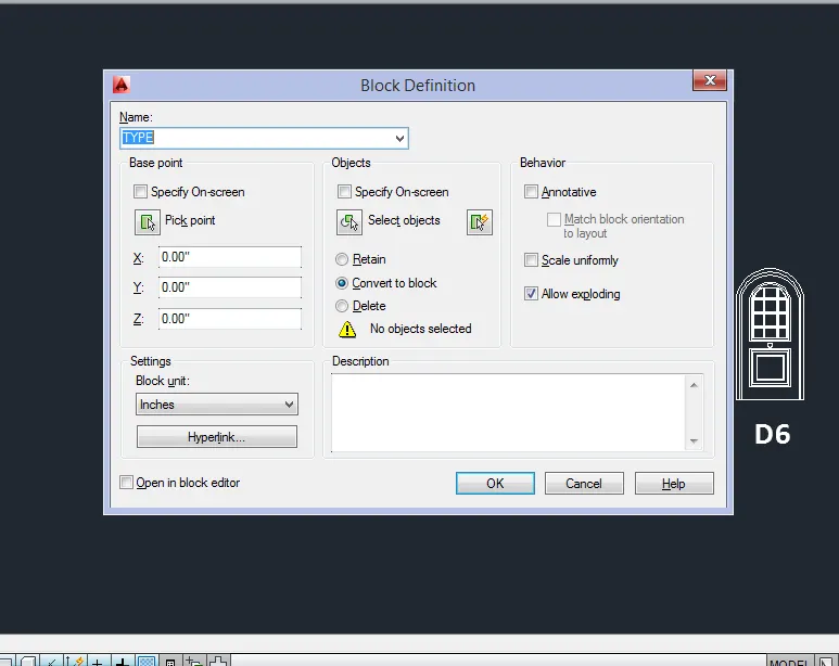
Select the objects all D1, D2, D3, D4, D5, D6 doors in the select object option
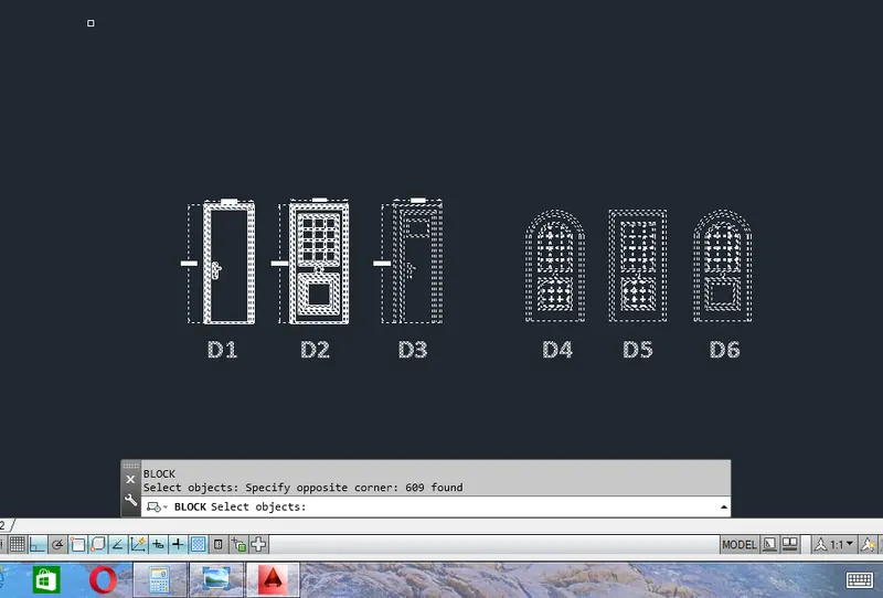
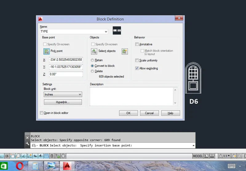
Pick the points using pick point option
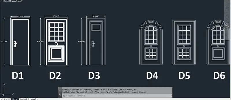
Result
5)
Aim: To design and draft given shapes by using given dimensions using autocad 2014
Procedure:
Go to start menu and select the autocad 2014 software click on that
And go to command tab and type Startup command
Give startup value as 1
Go to application menu and go to new option
Create new drawing dialogue box opens
Select units as decimal and precision 0.0 and press finish
And go to units and select units as decimal and precision 0.0 and insertion scale as millimeters
Then go to limits command and specify lower left corner as 500mm and upper right corner as 500mm
Go to line command and draw a line of length 750mm using line tool
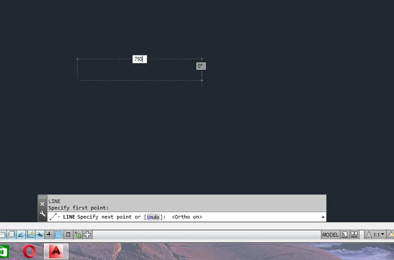
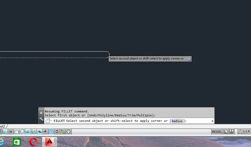
Go to fillet tool and add the fillet at the edges of a line or reinforcement steel
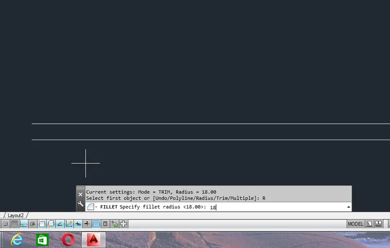
And fillet the edges using fillet command of radius 18mm
Go to block command and give the name as A(20mm)
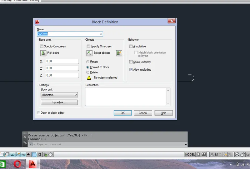
Select the objects for select objects option
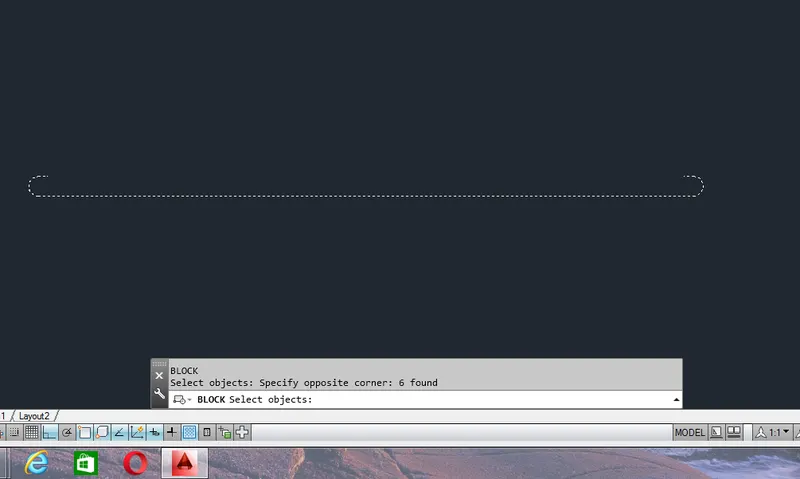
Pick the point for pick point option
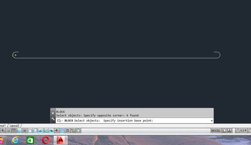
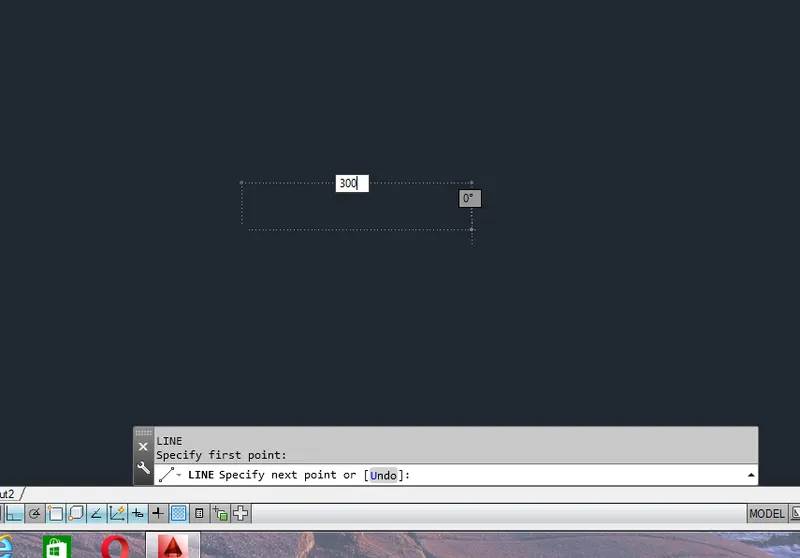
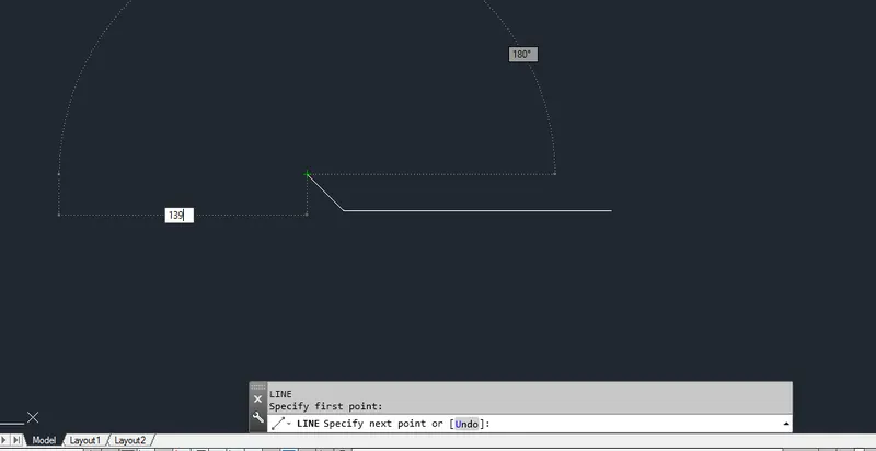
b) Take a line command and draw a line of length 300mm using line tool
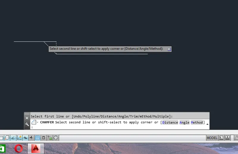
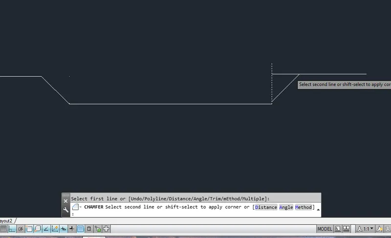
Select the chamfer command and select the distance option and give the length as 41mm and angle as 0degrees
And join the two lines using chamfer command
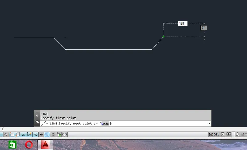
Give a line of 139mm using line command
Again take a chamfer command and give the chamfer distance as 41mm
And again take a line command and draw a line of length 139mm using line tool
Take a fillet of radius 14.5mm using fillet tool on both the sides
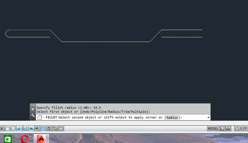
Go to block command and create a block name as B(16mm)
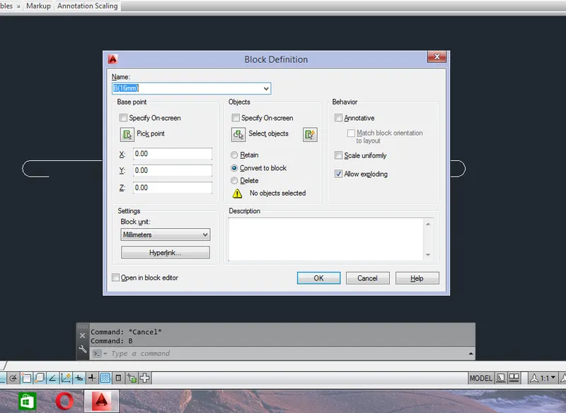
Select the objects using select object option
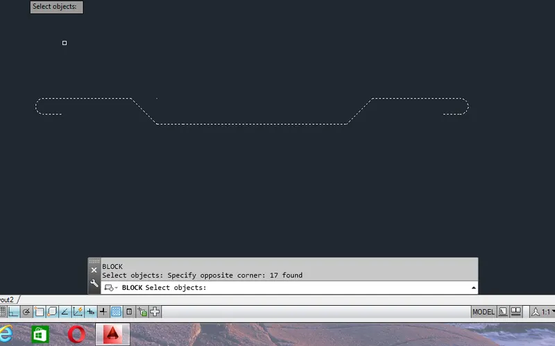
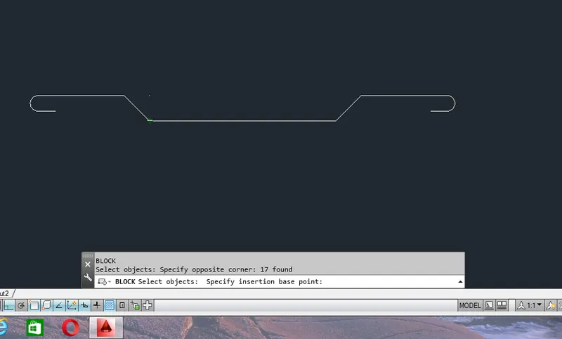
Pick the points using pick point option
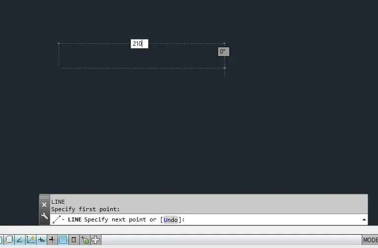
c) Again take a line of length 210mm using line tool
Take a chamfer at both the ends using chamfer tool
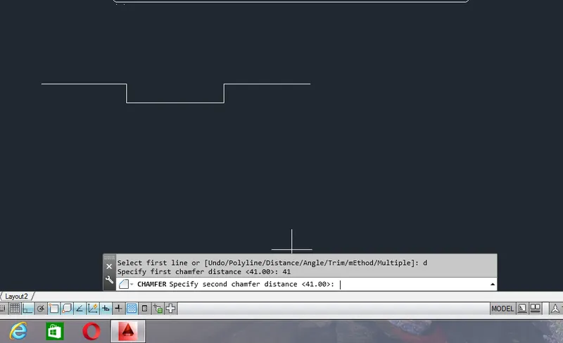
Chamfer the both the edges using chamfer tool
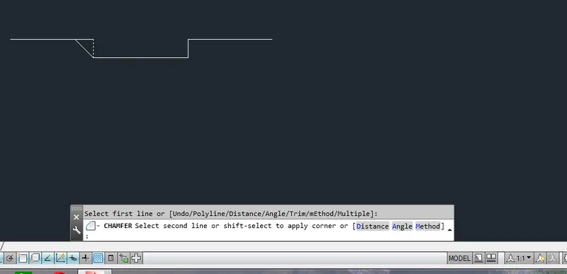
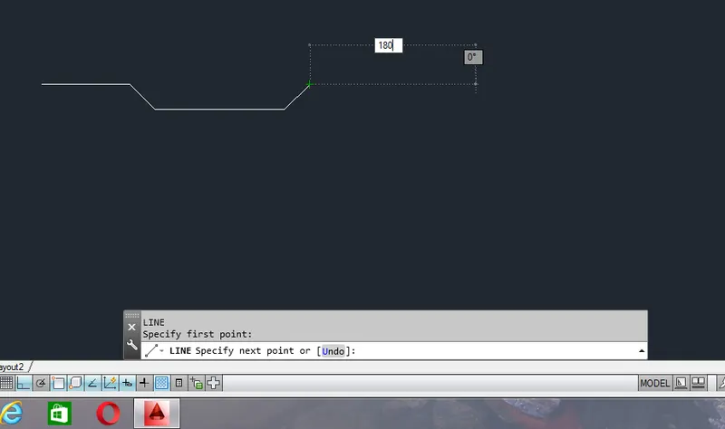
Take a line of length 180mm using line tool from the chamfered end
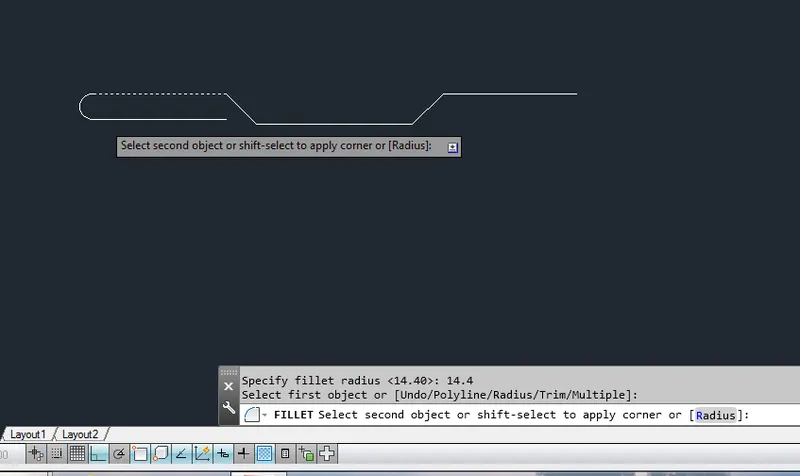
Take a fillet command and fillet both the ends using fillet tool of radius 14.4mm
Take the block command and save the block name as C(16mm)
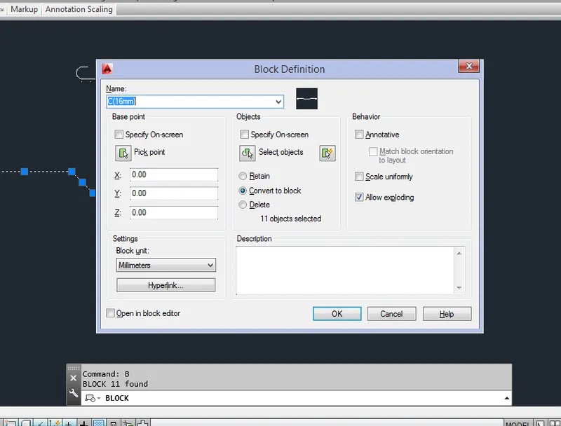
Select the objects using select object option
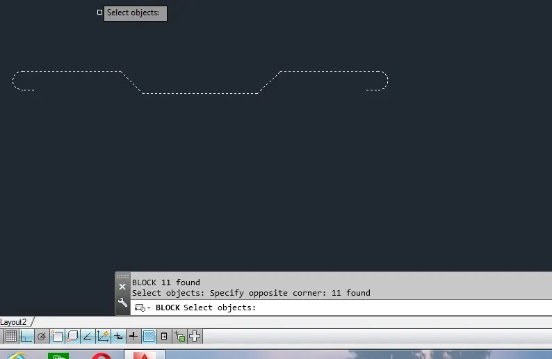
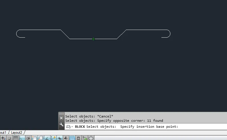
Pick the points using pick point option
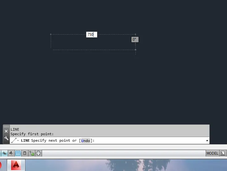
d) Take a line of length 750mm using line tool
Take a fillet of radius 11mm using fillet command at both the edges
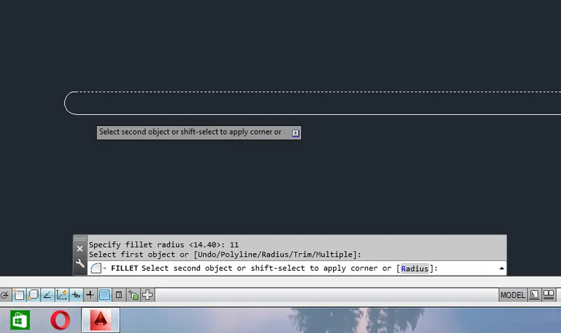
Go to block command and give the name as D(12mm)
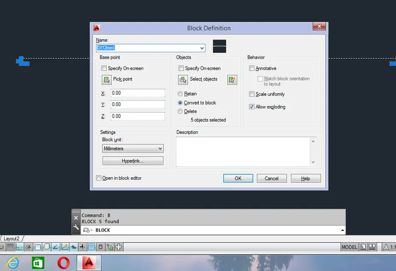
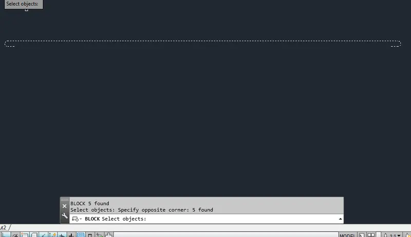
Select the objects using select object option
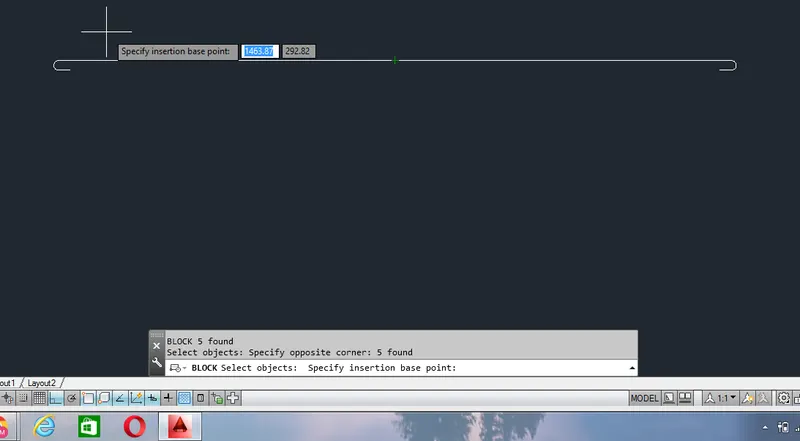
Pick the points using pick point option
e) Take a line of length 23mm using line tool as a width
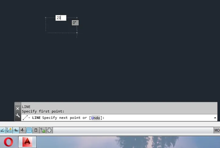
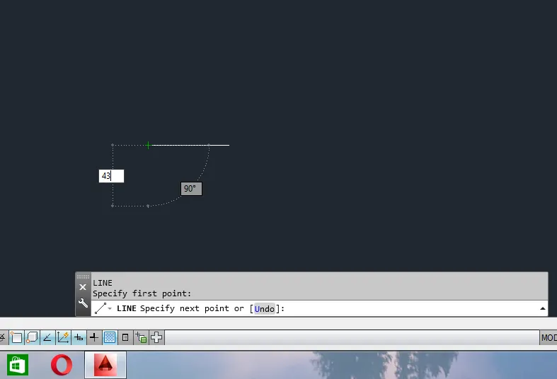
Take a line of length 43mm using line tool as a length
Take a fillet of radius 120mm using fillet option
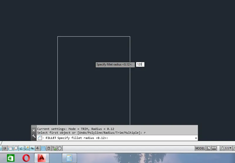
Fillet four corners of the reinforcement using fillet command
Go to block command and save the name as E(10mm)
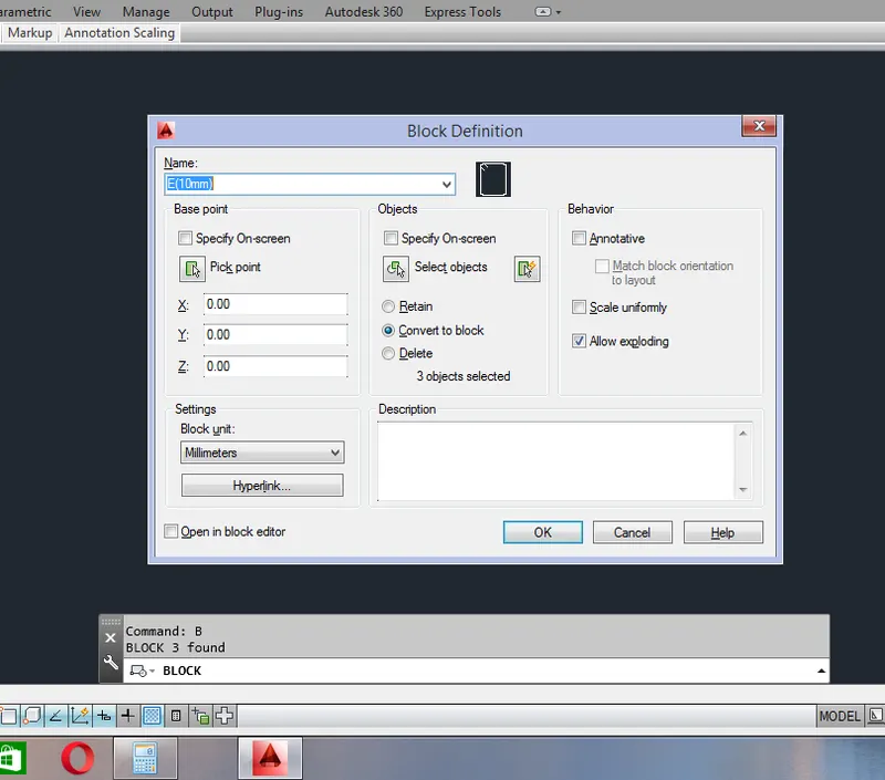
Select the objects by select object option
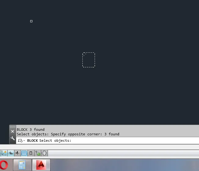
Pick the point using pick point option
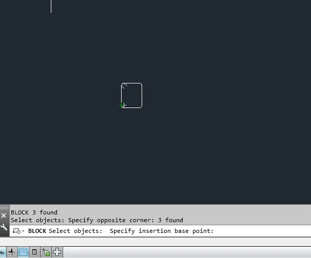
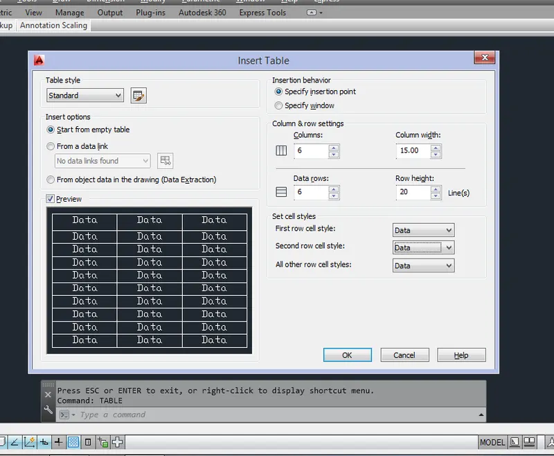
Now go to table command and insert a table
Insert table dialogue box opens and select the no of columns and rows in this dialogue box
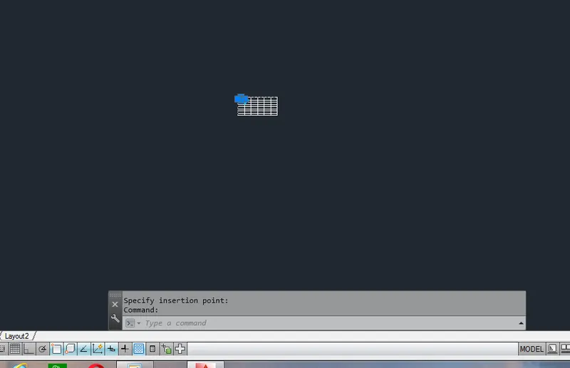
Specify insertion point option will appears and specify insertion point on the window
Add a text inside the table using text option, go to text option and add a text inside the table
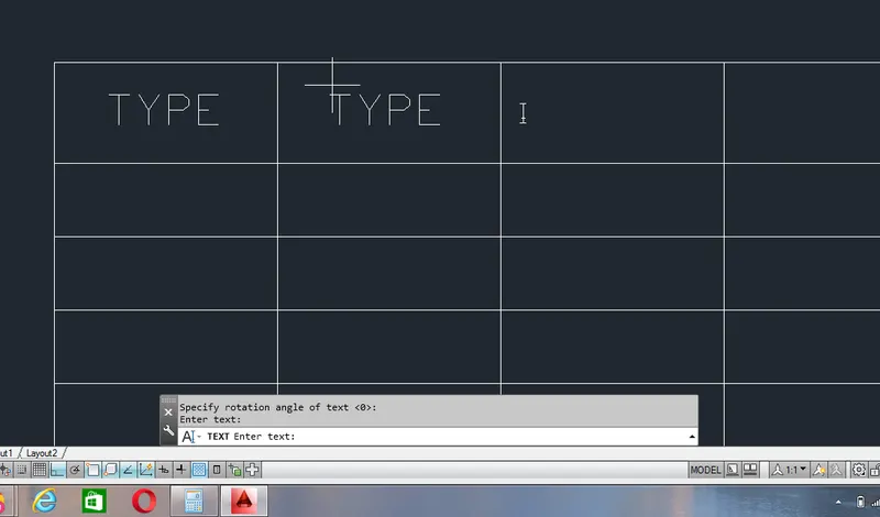
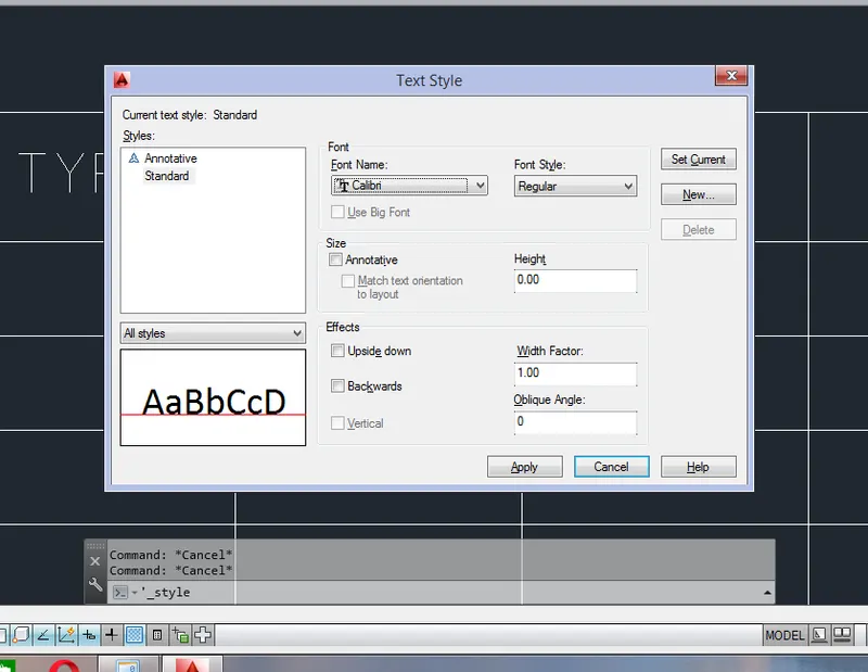
Change the text styles into a calibri style by using manage text style option
Text style dialogue box opens and select the calibri type of text
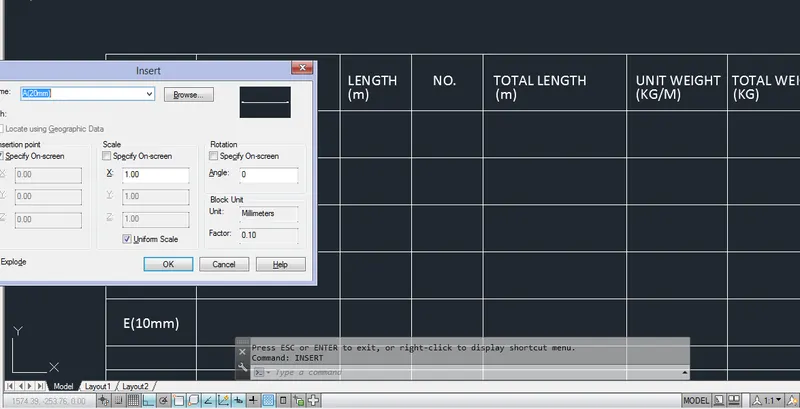
Go to insert command and insert the block by using insert command
Result: