Creating Bar Bending schedule, Different Door types, and Creation of standard drawing templates using AutoCad
- AIM
- 1. Create the templates as shown in Figures. Take the size of the title block as per industry standards or you can assume it as per the size of the paper. Use text and attributes wherever required. After creating the title block you need to save it as a block with names: Custom1_titleblock and Custom2_titleblock, respectively.
-
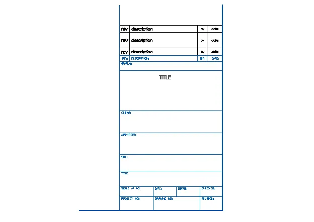
- SOFTWARE USED : AUTODESK AUTOCAD 2021
- PROCEDURE :
- Click on autocad aplication
- command : QNEW
- select the metric system
- click on ADVANCE SETTING
- Unit : decimal precision 0
- click on NEXT
- angle : decimal precision 0
- angle measure : EAST
- Angle direction : counter clockwise
- area : 100x100
- press : ENTER
- command : UN
- select decimal
- unit mm
- press : ENTER
- Command : UN (for units )
- set proper units DECIMAL
- command : LIMMAX (for limets )
- set the limets 100,100
- press : ENTER
- command : Z (for zoom )
- type A (for all )
- press : ENTER
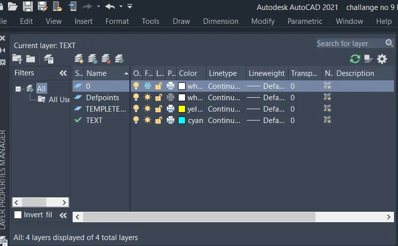
- go to the layer properties
- and create a new layer
- as shown below,
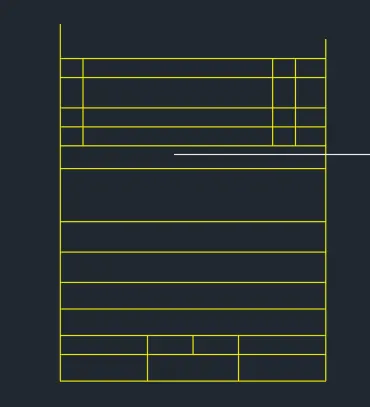
- command : REC (for rectangle )
- select a starting point
- click ON DIMENSION
- length : 350
- width : 425
- command : X (explode )
- click on rectangle
- press : ENTER
- command : o (for ofset )
- distance : 25,40,25,25,30,70,40,40,35,35.25,25
- give the ofset horizontly as above given distance
- command : TR (for triam )
- press : ENTER
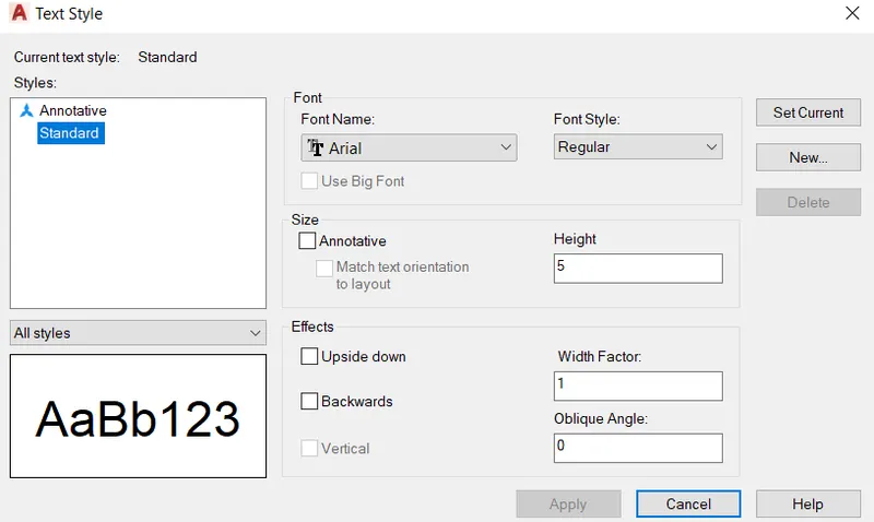
- Command : DIMENSION STYLE
- Click on MODIFY
- give heigtht 5
- select font ARIAL
- click on SET CURRENT
- PRESS : OK
- Command : MTEXT (for text )
- give the starting point
- heigth :
- rotation angle : 0 degree
- and write all TEXT by using MTEXT Command
- command : move
- select the object (TEXT )
- and place where as per requriment
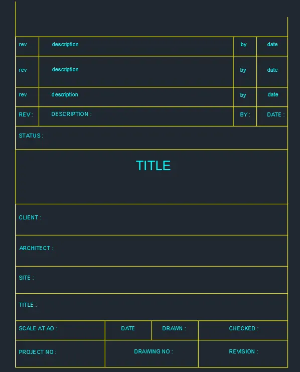
- command : B (for BLOCKS )
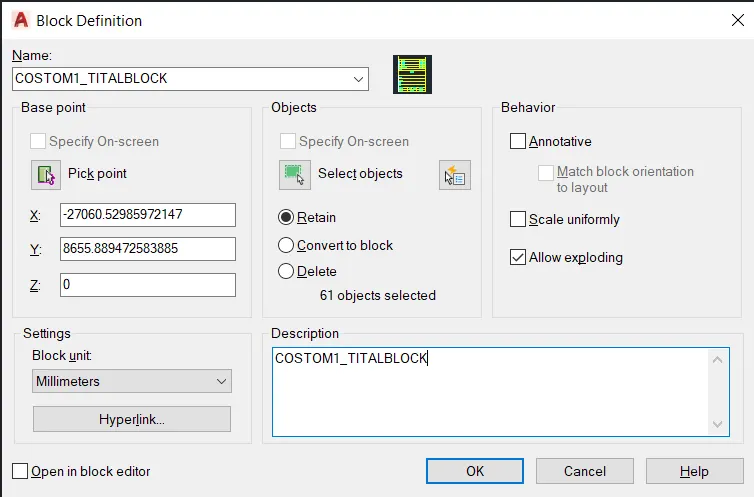
- give the NAME to block COSTOM1_TITLEBLOCK
- CLICK ON PICK POINT
- give the pick point
- press : enter
- then , SELECT OBJECT
- press : enter
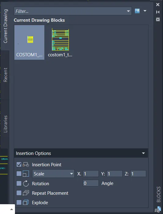
- command : I (for insert )
- select BLOCK
- And insert it where it is requried
- if size of blocks is large or small then it can be managed by command SCALE
- RESULTS :
- COMMAND USED :
- START : QNEW
- UNITS : UN
- LIMETS : LIMMAX
- RECTANGLE : REC
- OFSET : O
- TRIAM : TR
- TEXT STYLE
- TEXT : MTEXT
- BLOCKS : B
- INSERT : I
-
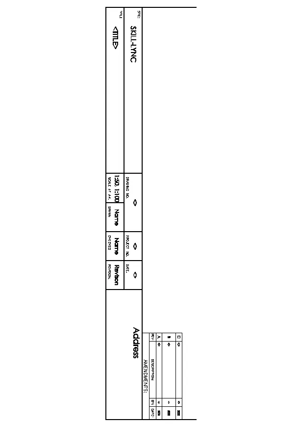
- CREATE A TEMPLETE AS SHOWN IN FIG. TAKE THE SIZE OF TITAL BLOCK AS PER STANDARDS . USE TEXT AND ATTRIBUTES WHERE REQURIED AFTER A CREATING A BLOCK YOU NEED TO SAVE IT AS A BLOCKS WITH NAME coustom2_ titleblocks RESPECTIVELY.
- PROCEDURE :
- Click on autocad aplication
- command : QNEW
- select the metric system
- click on ADVANCE SETTING
- Unit : decimal precision 0
- click on NEXT
- angle : decimal precision 0
- angle measure : EAST
- Angle direction : counter clockwise
- area : 100x100
- press : ENTER
- command : UN
- select decimal
- unit mm
- press : ENTER
- Command : UN (for units )
- set proper units DECIMAL
- command : LIMMAX (for limets )
- set the limets 100,100
- press : ENTER
- command : Z (zoom )
- type A (for all )
- press : enter
- go to the layer properties
- and create a layer
- as shown below
- command : REC (For rectangle )
- give the starting point
- length : 160
- width :1000
- press : enter
- command : x (for explode )
- click on rectangle
- press : enter
- command : O (for ofset )
- distance 80,80
- give vertically two ofset as a distance of 80
- command : REC ( for rectangle )
- give the starting point
- length :175
- width :350
- press : enter
- command : MOVE
- select the rectangle
- and placed where requried
- command : x (for explode )
- click on rectangle
- press : ENTER
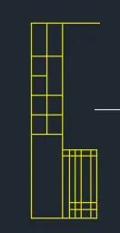
- command : O (for ofset )
- distance : 35 ,30,30,50,30
- give the horizontal ofset line to the second rectangle
- command : TR (for triam )
- triam the extra lines
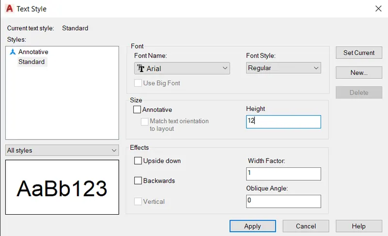
- command : TEXT STYLE
- select the font type ARIAL
- text height : 12
- set as a current
- clock on OK
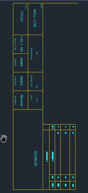
- command :MTEXT (FOR TEXT )
- give the starting point
- give the height : 12
- and rotation angle : 270
- write the text
- write all the text by using MTEXT command
- command : MOVE
- select the object (text )
- and placed as proper way
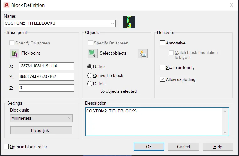
- command : B (for BLOCKS )
- give the name of blocks COSTOM2_TITLEBLOCK
- Then, click on PICK PONT
- then SELECT THE OBJECT
- PRESS : ENTER
- command :I (for insert )
- select the object
- and insert where it is requried
- if size of blocks is large or small the it will be managed by scale command
- press : enter
- RESULTS :
- COMMAND USED :
- START : QSTART
- UNITS : UN
- LIMETS : LIMMAX
- ZOOM : Z
- TRIAM : TR
- RECTANGLE : REC
- EXPLODE : X
- DIMENSION STYLE
- TEXT : MTEXT
- BLOCKS : B
- INSERT : I
-
- AIM :
-
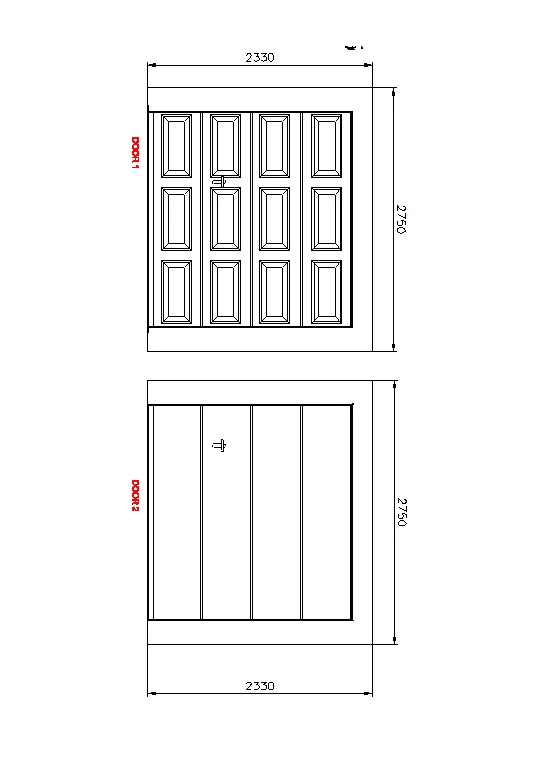
2. Create the doors type for warehouse as shown in the Figure. You need to create each door type as per standard size or given dimensions. Create the blocks of this door type after creating them.
- PROCEDURE :
- Click on autocad aplication
- command : QNEW
- select the metric system
- click on ADVANCE SETTING
- Unit : decimal precision 0
- click on NEXT
- angle : decimal precision 0
- angle measure : EAST
- Angle direction : counter clockwise
- area : 100x100
- press : ENTER
- command : UN
- select decimal
- unit mm
- press : ENTER
- Command : UN (for units )
- set proper units DECIMAL
- command : LIMMAX (for limets )
- set the limets 100,100
- press : ENTER
- command : Z (zoom )
- type A (for all )
- press : enter
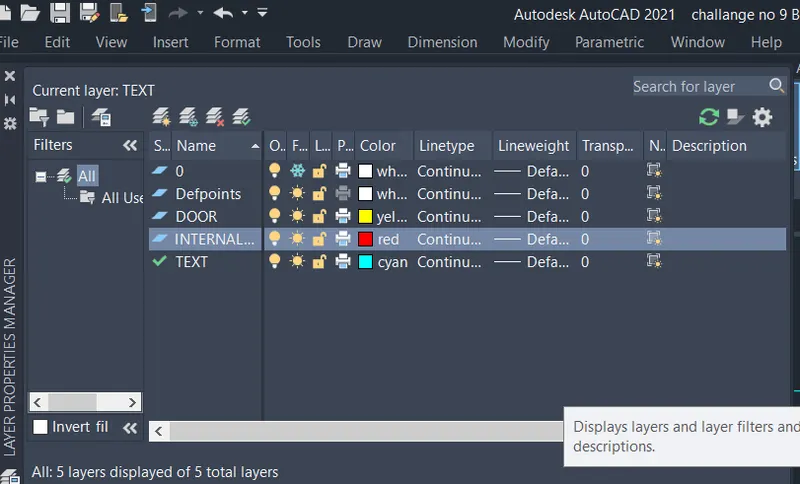
- create a new layers
- layers are created as shown below
-
- command : REC (FOR rectangle )
- give the starting point
- click on DIMENSION
- length : 2330
- width :2750
- press : ENTER
- Command : X (explode )
- click on Rectangle
- command : ofset
- distance : 200
- mark ofset line at a distance 200 mm horizontically top and bottem and vertically
- command : ofset
- distance : 20
- click on MULTIPLE
- and give the ofset line
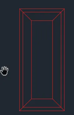
- command : REC (for rectangle )
- give starting point
- cick on DIMENSION
- length : 265
- width : 602
- press: ENETR
- command : o (For ofset )
- distance : 20 and 50 internically to the rectangle
- command : L (for line )
- put OBJECT ON
- And join the lines
- command : copy
- select rectangle and copy rectangle and placed properly
- command : MI (for mirror )
- mirror the object properly
- command : TR (for triam )
- triam the extra lines
- command : Mtext
- give the starting point
- rotation angle : 270
- and write the text
- press : enter
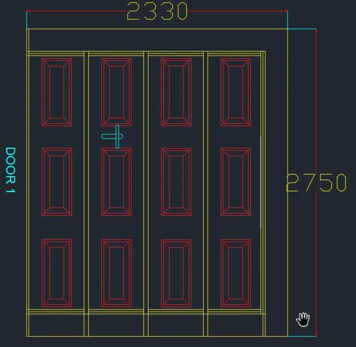
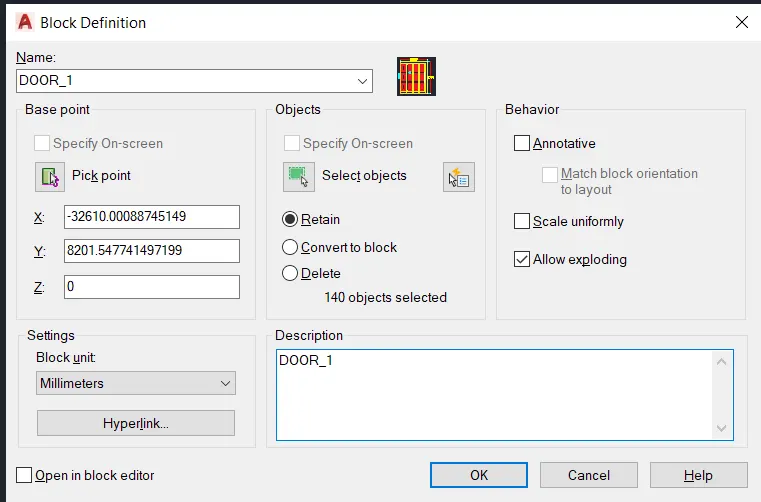
- command : B (for blocks )
- give the name of blocks is DOOR_1
- SELECT PICK POINT
- SELECT OBJECT
- press : OK
- Command : I (insert )
- select the object
- and insert where it is requried
- if size of a blocks is large or small then it is managed by scale command
- press : enter
- AIM
- CREATE DOOR FOR WAREHOUSE AND GIVE THE STANDARD DIMENSIONS . AND THEN CREATE A BOCKS OF DOOR
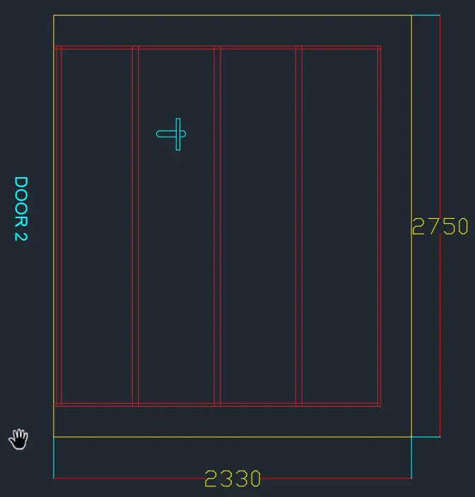
- DOOR 2
- PROCEDURE
- go to the layer properties
- select the proper layer for door
- layers are alrady created
- select door layer and make it current
- press : ENETR
- Command : REC (for rectangle )
- give the starting point
- click on DIMENSION
- length : 2330
- width : 2750
- press : enter
- command : o (for ofset )
- distance : 20
- click on MULTIPLE
- give the ofset at a distance of 20 internally to the rectangle
- command : x (for explode )
- click on rectangle
- press : ENTER
- commend : divide
- select the line
- no of segment 4
- press : enter
- put object snap ON
- command : L (for line )
- mark the line
- starting point is divide point
- command : O (for ofset )
- distance : 10
- give ofset line of divide line both left and right
- command : TR (for triam )
- triam the middle line
- command : DIMLIN (for dimension )
- give the dimension
- command : MTEXT (for text )
- give the start point
- give the proper heigth and
- rotation angle : 270
- write a text
- as shown below fig
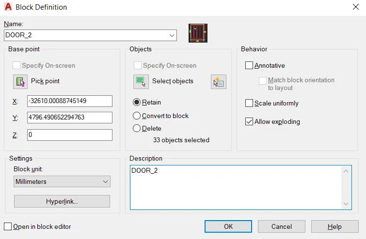
- command : B (for blocks )
- give the name of a blocks is DOOR_2
- select a pick point
- then select object
- press : OK
- Command : I (for insert )
- select the block name as DOOR _2
- and insert any where it is requried
- if the size of blocks is large of small then it will be managed by SCALE command
- RESULTS :
- COMMAND USED :
- START : QNEW
- UNITS : UN
- LIMET : LIMMAX
- OFSET : O
- RECTANGLE : REC
- LINE : L
- EXPLODE : X
- TRIAM : TR
- DIMENSION : DIMLIN
- TEXT : MTEXT
- BLOCKS : B
- INSERT : I
-
- AIM
-
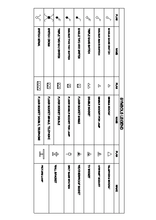
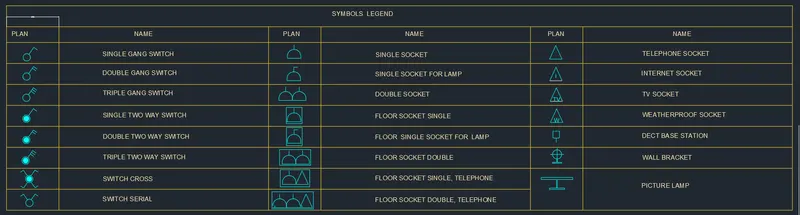
3. Create each symbol as a block with the name given in the legend. After creating the blocks arrange them in the legend as shown in the Figure.
- PROCEDURE :
- Click on autocad aplication
- command : QNEW
- select the metric system
- click on ADVANCE SETTING
- Unit : decimal precision 0
- click on NEXT
- angle : decimal precision 0
- angle measure : EAST
- Angle direction : counter clockwise
- area : 100x100
- press : ENTER
- command : UN
- select decimal
- unit mm
- press : ENTER
- Command : UN (for units )
- set proper units DECIMAL
- command : LIMMAX (for limets )
- set the limets 100,100
- press : ENTER
- command : Z (zoom )
- type A (for all )
- press : enter
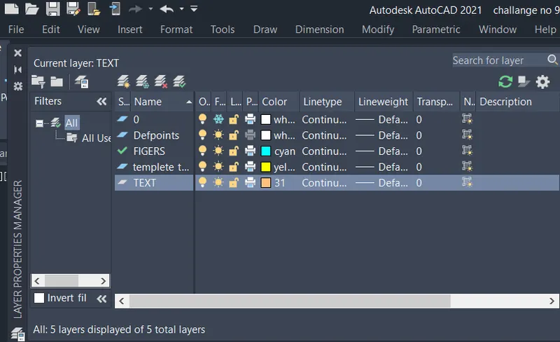
- go to the layer properties
- create the new layers
- the new layes are created below
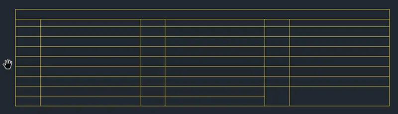
- command : REC (for rectangle )
- select the starting point
- click on DIMENSIONS
- Length : 3750
- width : 715
- press : ENTER
- command : x (for explode )
- click on rectangle
- press : ENTER
- command : o (for ofset )
- distnce : 75
- click on MULTIPLE
- and mark 9 horizontal ofset lines
- command : o (for ofset )
- distance : 250,1000,250,1000,250,1000
- mark vertical ofset line distance shown above
- press : enter
- command : TR (for triam )
- triam the extra lines
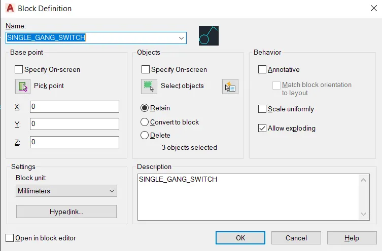
- for blocks
- command : c (for circle )
- draw a circle
- command : L (for line )
- and draw the lines

- command : B (for blocks )
- give the name of blocks is SINGLE_GANG_SWITCH
- give the PICK POINT
- SELECT THE OBJECT
- PRESS : OK
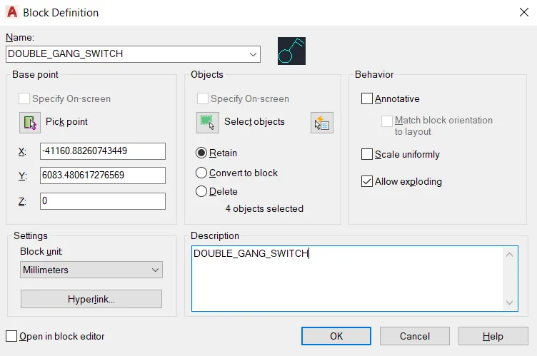
- Again for block ,
- command : c (for circle )
- draw the circle
- command : L (for line )
- draw a line
- L shape structure
- command : O (for ofset )
- distance : 10
- press : enter

- command :B (for blocks )
- give name of blocks is DOUBLE_GANG_SWITCH
- SELECT PICK POINT
- THEN SELECT OBJECT
- PRESS : OK
- for block :
- command : c(for circle )
- draw the circle
- command : L (for line )
- and draw the line
- command : O (for ofset )
- distance 5,10,15
- press : ENTER

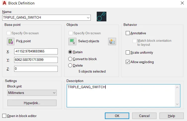
- Command : B (for blocks )
- give the name of blocks is TRIPLE_GANG_SWITCH
- give the pick point
- and then select the object
- press : ENTER
- for blocks
- command : circle
- and draw the circle
- command : L (for a line )
- draw the line
- command : DO (for donut )
- and give donut to the internal circle

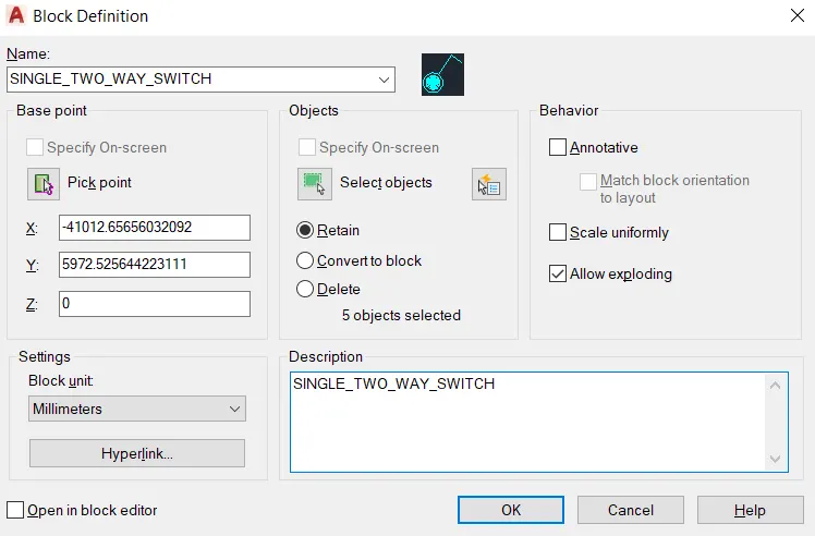
- command : B (for blocks )
- give the blocks name is SINGLE_TWO_WAY_SWITCH
- GIVE THE PICK POINT
- SELCT THE OBJECT
- PRESS : ENTER
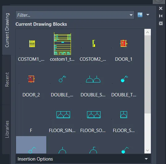
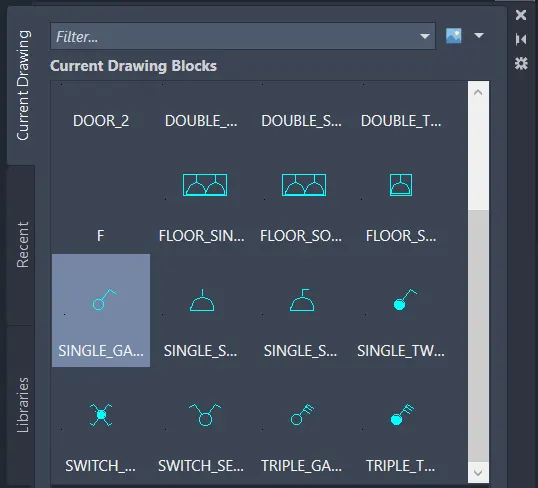
- in this way create a symbols and make its blocks
- Command :MOVE
- select the object
- and placed properly in a table
- command : MTEXT (for text )
- and write all text
- commad : MOVE
- and placed all text properly
- RESULTS :
- COMMAND USED:
- START : QNEW
- UNITS : IN
- LIMETS : LIMMAX
- ZOOM : Z
- LINE : L
- RECTANGLE : REC
- OFSTET : O
- TRIAM : TR
- TEXT : MTEXT
- BLOCK : B
- DONUT : DO
- INSERT : I
- AIM :
-
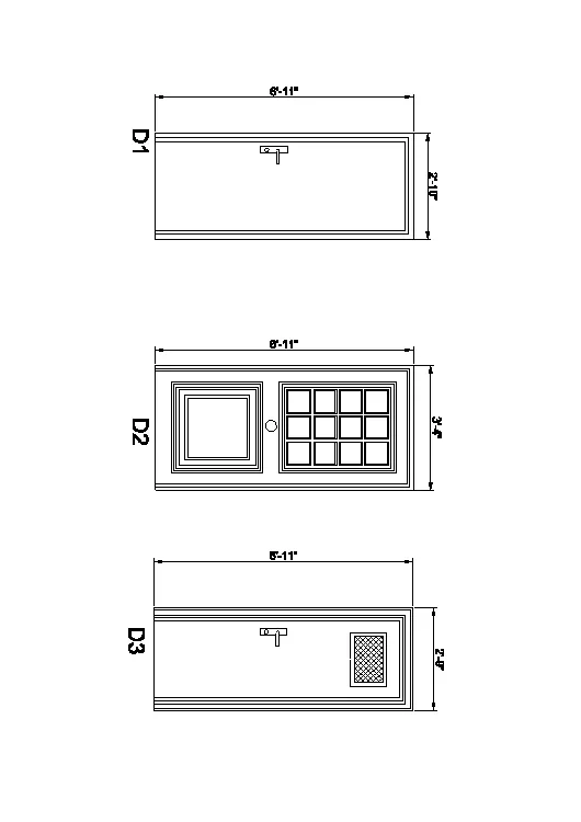
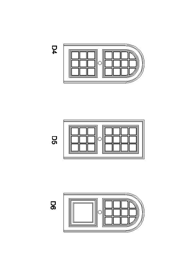
4. Create the door type for residential building as a block. Save the name of the blocks as type. Use given dimensions or assume dimensions as per industry standards.
- PROCEDURE :
- Click on autocad aplication
- command : QNEW
- click on ADVANCE SETTING
- Unit : ENGINEERING precision 0',0"
- click on NEXT
- angle : DECIMAL precision 0
- angle measure : EAST
- Angle direction : counter clockwise
- area : 100'x100'
- press : ENTER
- command : UN
- select ENGINEERING
- unit INCHES
- press : ENTER
- Command : UN (for units )
- set proper units DECIMAL
- command : LIMMAX (for limets )
- set the limets 100',100'
- press : ENTER
- command : Z (zoom )
- type a for all
- press : enter
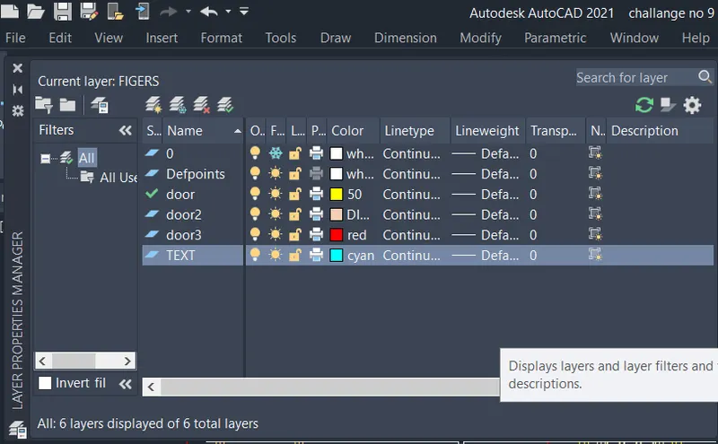
- go to the layer propertices
- create a new layer
- the layer shown below
- DOOR 1:
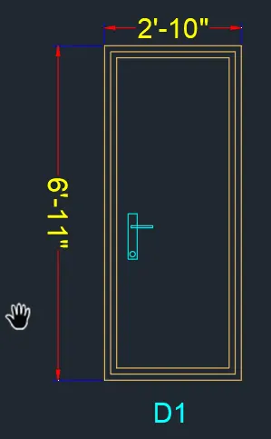
- Command : REC (for rectangle )
- give the starting point
- click on DIMENSION
- length : 2',10"
- width :6',11"
- press : enter
- Command : O (for ofset )
- distance : 2"
- again
- command : o (for ofset )
- distance : 2"
- and give the ofset internally
- command : REC (FOR RECTANGLE )
- and draw the rectangle
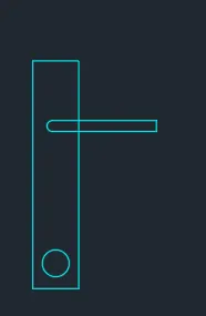
- command : C (for circle )
- and draw the circle inside the rectangle
- command : DIMLIN (for dimension )
- give the dimension to the door
- command : MTEXT (FOR TEXT )
- write a text
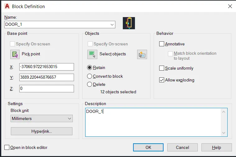
- command : B (for block )
- give the block name is DOOR_1
- SELECT the pick point
- then select the object
- press :OK
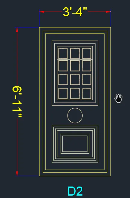
- FOR DOOR 2 :
- PROCEDURE :
- command : REC (for rectangle )
- select the start point
- click on DIMENSION
- length : 3',4"
- width : 6',11"
- press : enter
- command : O (for ofset )
- distance :2",2",4"2",2"
- give the ofset internally distance is given above
- command : REC (for rectangle )
- select the startig point
- click on DIMENSION
- length : 5"
- width : 5"
- press : enter
- command : O (for ofset )
- distance : 0.2"
- give the ofset outside to the rectangle
- command : MI (for mirror )
- and mirror the object
- as shown in below diagram
- command : C (for circle )
- draw the circle
- command : REC (for rectangle )
- draw the rectangle below the circle
- command : o (for ofset )
- distance : 1",1",1",1",2",1"
- give the ofset internally distance shown above to the rectangle
- command : DIMLIN (for dimension )
- give the dimension
- command : MTEXT (for text )
- then write the text
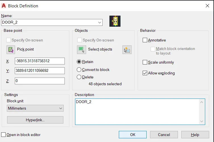
- command : B (for a blocks )
- give the blocks name DOOR_2
- SELECT THE PICK POINT
- THEN SELECT THE OBJECT
- PRESS : ok
- FOR DOOR 3:
- PROCEDURE :
- command : REC (for rectangle )
- select the start point
- click on DIMENSION
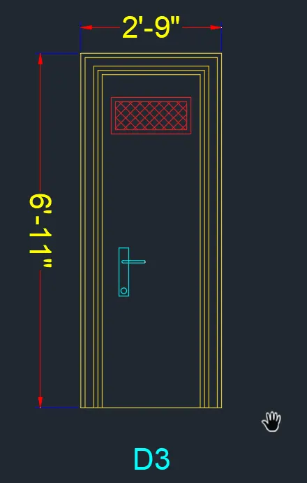
- length : 2',9"
- width : 6',11"
- press : ENTER
- command : O (for ofset )
- distance : 1",2"1",1"
- give the ofset internally to the rectangle
- command : REC (for rectangle )
- select the start point
- click on DIMENSION
- length : 1',7"
- width :9"
- press : enter
- command : O (for ofset )
- distance :1"
- give the ofset internally to the rectangle
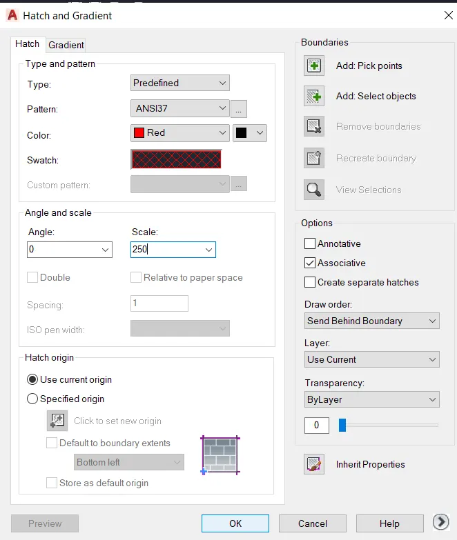
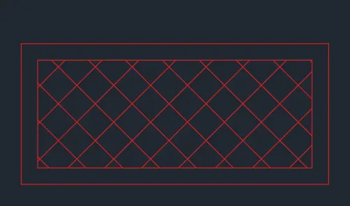
- command : HATCH
- hatch patern shown below,
- command : copy
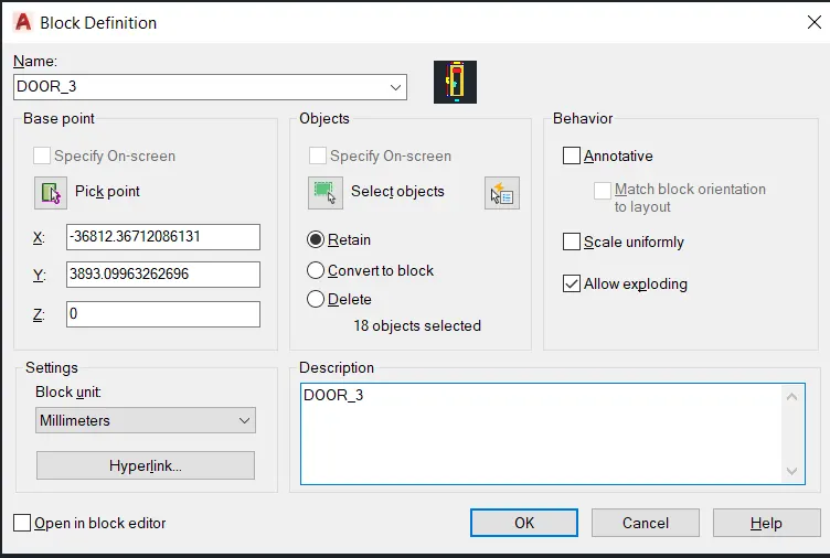
- copy the handle of door and placed in door 2
- command : TR (for triam )
- triam the extra lines
- command :DIMLIN (for dimension )
- give the dimension
- command : MTEXT (for text )
- write the by using command
- FOR DOOR 4 :
- PROCEDURE :
- command : REC (for rectangle )
- select the start point
- click on DIMENSION
- length : 6',3"
- width : 4'
- press : ENTER
- command : X (for explode )
- click on rectangle
- press : enter
- command : F (filite )
- give the filite radius
- then select the line
- and filite it
- command : TR (for triam )
- triam the extra part
- press : ENTER
- command : JOIN
- joint the lines and filite part
- press : ENTER
- command : O (for ofset )
- distance :3" and then 2"
- give the ofset distance 3" and 2" internally
- command : REC (for rectangle )
- select the start point
- click on DIMENSION
- length : 2',9"
- width : 3',2"
- press : ENTER
- Command : F (for filite )
- give the filite radius
- and filite it
- command : TR (for triam )
- triam the extra lines
- command : JOIN
- join the rectangle and filite portion
- command : AR (for array )
- by using array command draw the interal portions
- command : C (for circle )
- draw the circle below the rectangle
- command : REC (for rectangle )
- select the start point
- click on DIMENSION
- Length : 2',9"
- width :1',8"
- press : enter
- command : O (for ofset )
- give the ofset to the rectangle
- command : RECTANGLE
- draw the rectangle inside the large rectangle
- command : AR (for array )
- array this intsrnal rectangle
- and draw this part
- command : MTEXT (for text )
- write the text
- press : ENTER
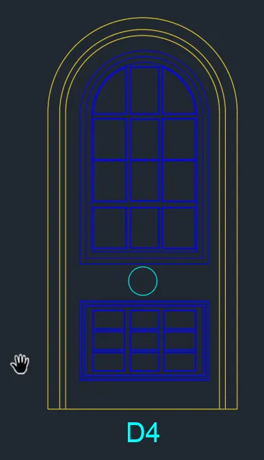
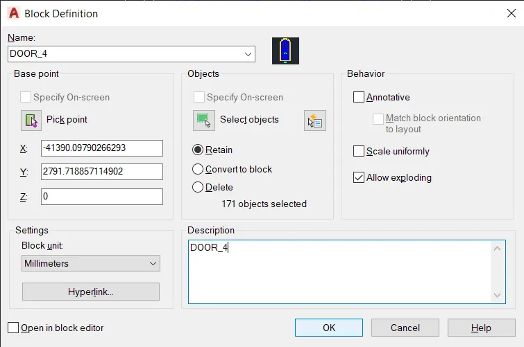
- FOR DOOR 5:
- PROCEDURE :
- command : REC (for rectangle )
- select the start point
- click on DIMENSON
- length :4',1"
- width : 7'7"
- press : ENTER
- Command : O (for ofset )
- distance : 2" 1" ,1"
- give the ofset to the rectangle internally distance shown above
- command:REC (For rectangle )
- select the start point
- click on DIMENSON
- Length : 2',7"
- width :3'9"
- press : ENTER
- command : O (for ofset )
- distance 1"
- give 3 no of ofset internally to the rectangle at a distance of 1"
- command : REC (for rectangle )
- draw the rectangle
- command : AR (for array )
- array this rectangle
- then
- commad: C (for circle )
- draw the circle
- then command REC (for rectangle )
- draw the rectangle
- then command : O (for ofset )
- give the ofset to the rectangle
- command : REC (for rectangle )
- draw it and then array it
- command : MTEXT (for text )
- write the text
- press : ENTER
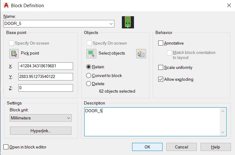
- command : B (for blocks )
- give the name of blocks is DOOR_5
- select the pick point
- then select the object
- press : OK
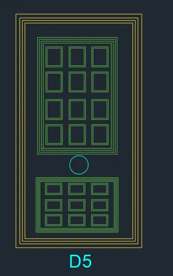
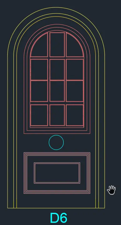
- FOR DOOR6 :
- PROCEDURE :
- Command : REC (For rectangle )
- select the start point
- click on DIMENSION
- length :3',9"
- width :6',3"
- press : ENTER
- COMMAND : X (For explode )
- click on RECTANGLE
- press : enter
- command : F(filite )
- give the filite radius
- click on lines
- and filite it
- command : TR (for triam )
- triam the extra lines
- command : JOIN
- click on rectangle and filited portion
- press : ENTER
- COMMAND : O (for ofset )
- distance : 2" and 1"
- give the ofset at a distance given above internally to the door
- command : REC (for rectangle )
- give the start point
- click on DIMENSION
- length : 2',9"
- width :3',2"
- press : ENTER
- command : F(for filite )
- give the filite radius
- click on lines
- and filite it
- press : enter
- command : TR (for triam )
- triam the extra lines
- command : JOIN
- joint it rectangle and filited portion
- command : O (for ofset )
- distance : 1", again 1"
- press : enter
- command : REC (for rectangle )
- draw the rectangle
- command : O (for ofset )
- distance 0.2"
- press : enter
- command : AR (for array )
- array this rectagle
- command : C (for circle )
- draw the circle
- command : REC (for rectangle )
- draw the rectangle
- command : O (for ofset )
- give the ofset to the circle
- as shown beow fig
- command : MTEXT (FOR TEXT )
- give the text
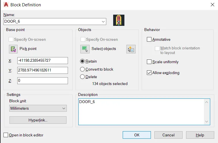
- command : B (for blocks )
- give the name of blocks is DOOR_6
- Select the pick point
- then select the object
- and click : OK
- RESULTS :
- START : QNEW
- UNITS : UN
- LIMETS : LIMMAX
- ZOOM : Z
- OFSET : O
- RECTANGLE : REC
- TRIAM : TR
- LINE : L
- CIRCLE : C
- EXPLODE : X
- TEXT : MTEXT
- DIMENSION : DIMLIN
- BLOCKS : B
- INSERT : I
- DOOR 1 :
-
- FOR DOOR 2 :
- FOR DOOR 3 :
-
- FOR DOOR 4 :
-
- FOR DOOR 5 :
-
- FOR DOOR 6 :
-
- AIM :
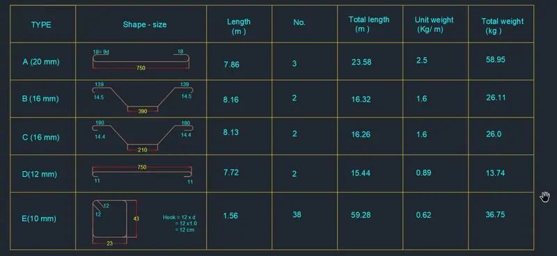
- 5. Create each shape as a block as shown in the Figure. Save the block and insert them on the table as shown in the Figure.
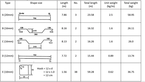
- PROCEDURE :
- Click on autocad aplication
- command : QNEW
- select the metric system
- click on ADVANCE SETTING
- Unit : decimal precision 0
- click on NEXT
- angle : decimal precision 0
- angle measure : EAST
- Angle direction : counter clockwise
- area : 100x100
- press : ENTER
- command : UN
- select decimal
- unit mm
- press : ENTER
- Command : UN (for units )
- set proper units DECIMAL
- command : LIMMAX (for limets )
- set the limets 100,100
- press : ENTER
- command : Z (zoom )
- type A (for all )
- press : enter
- go to the layer properties
- and create a new layer
- created layer are shown below
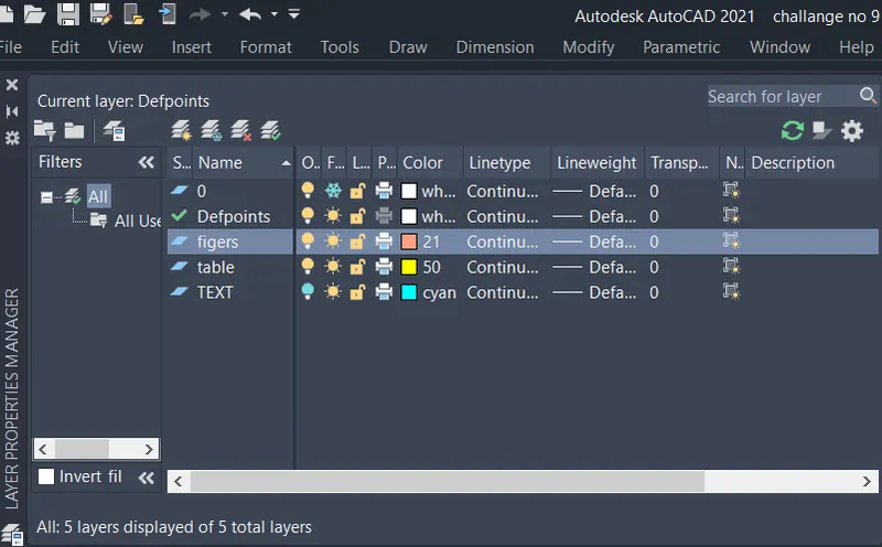
- command : REC (for rectangle )
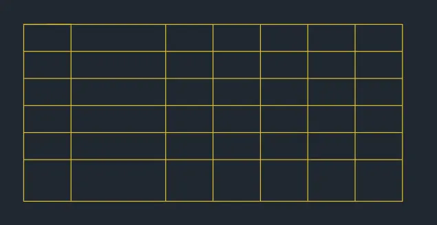
- give the start point
- click on DIMENSION
- length : 2800
- width : 1300
- press : ENTER
- Command : X (for explode )
- click on RECTANGLE
- press : ENTER
- command : O (for ofset )
- distance : 200
- click on MULTIPLE
- and give the horizontal distance
- press :ENTER
- THE TABLE IS PREPARED
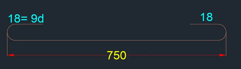
- command : L (for line )
- draw the line distance of 750
- command : o
- distance : 38
- command : F (filite )
- give the filite radius
- and filete it
- command : TR (for triam )
- triam the extra lines
- presss : ENTER
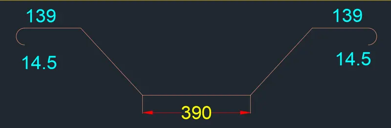
- inthis way draw the all figers shown below
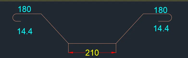
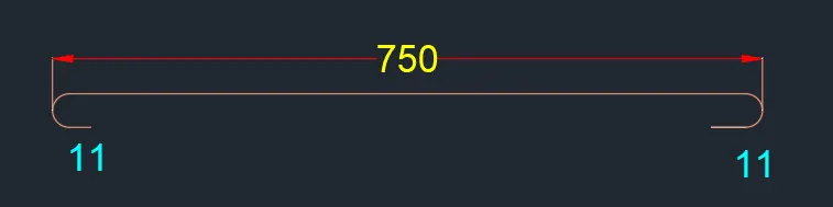
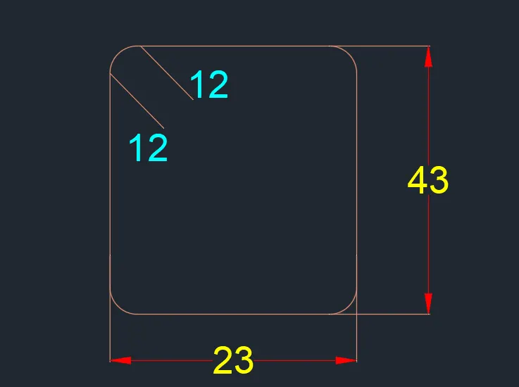
- command :MTEXT (For text )
- write the all text
- press : enter
- command : MOVE
- select the object (text and figers )
- and placed it properly
- press : enter
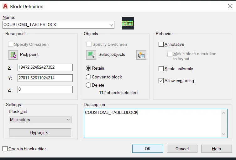
- command : B (for blocks )
- give the name of block is COUSTOM3_TABLEBLOCK
- select the pick point
- then select the object
- press : OK
- RESULTS :
- COMMAND USED :
- START : QNEW
- UNITS : UN
- LIMETS : LIMMAX
- ZOOM : Z
- RECTANGLE :REC
- LINE : L
- FILETE : F
- OFSET : O
- EXPLODE : X
- TEXT :MTEXT
-