Creating Bar Bending schedule, Different Door types, and Creation of standard drawing templates using AutoCad
AIM:
- Template, Inserting Text and Attributes
- Doors of Warehouse and Placing it in blocks
- Electrical legends and making it blocks
- Different types of door for Residential project
- Drawing bars, making it as block and making it as a table as bar bending schedule.
Commands used:
Insert, Attributes, field, Rectangle, Array, Polyline/Line, Multi-text/Text, Offset, Extend, Fillet, Mirror, Trim, Move, Block, Block edit, Rotate, Hatch, Annotate.
INTRODUCTION:
1). Aim: Creating Templates, Inserting Text and Attributes.
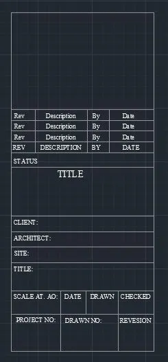
- Custom 1_Title Block
- Custom 2_Title Block
PROCEDURE
Custom 1_Title Block:
- Create a rectangle of size 66.63mm and 158mm
- Divide it with line for the text box into columns
- For rows, take offset of 5,10,5,5,8,30,15,15,20,20,10,15 mm
- By multiline text, type rev, description, by, date on the first row by text height 2.5 & style-Times New roman.
- As it repeated in the other two rows, take array give column as1, row as 3, spacing b/w rows as 7.
- Again, use multiline text & type the required text in caps with text height 1.5 & style as Times New Roman.
Creating block:
Command : B- block definition dialogue box appears- give name as’ Custom 1Title block’ select pick point & select a point in the table – select the object – select the whole table including the text give scale uniformly & tick allow exploding select convert to block option.
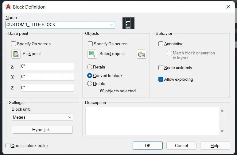
As we have selected retain the object it will be retain & same as the actual drawing & a block is created for the objects that we have selected, if we want to use the block go to insert select the object & insert it.
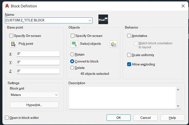
Custom 2_Title Block:
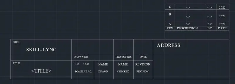
Draw rectangle of 252 & 46mm lines divide to the required rows & columns.
With the use of multiline text insert the following height 2.5
Create a small rectangle at the right corner, explode it, create rows & columns.
By attributes, create the text inside it, command ‘ ATT ‘ – attribute the definition dialogue box appears.
Insert the tagline- tag we are giving, visible before creating the block.
Prompt: Question we need to add what we need to enter.
Default: the value shown in drawing after making it as a block.
For. Eg. In the first row 1st column ‘ C ‘ is the text to be displayed, command &’ ATT ‘
Place the tagline on the place we need to hear 1st row 1st column of the box created. Create attributes similarly for the rest of the text, the attributes created are:
Now create a block command ‘ B’ with name Custom 2 title block, select the whole title block & make it as a block, after creating it as a block we can see that all attributes will change to their default values.
2). Aim: Creating Doors for Warehouse & placing it in blocks
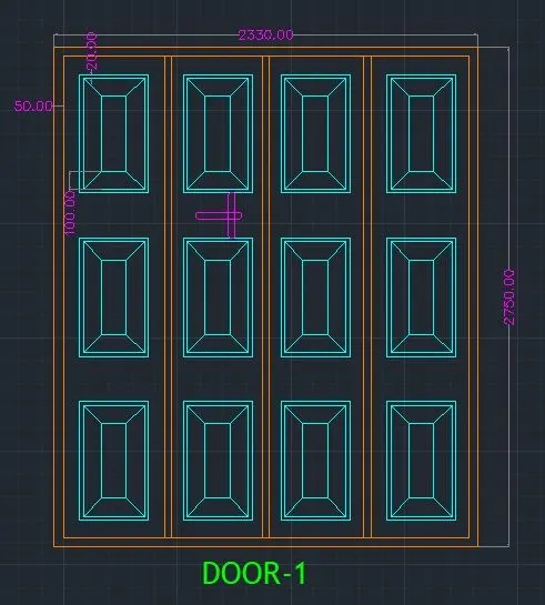
- Door-1 -2330 x 250 mm
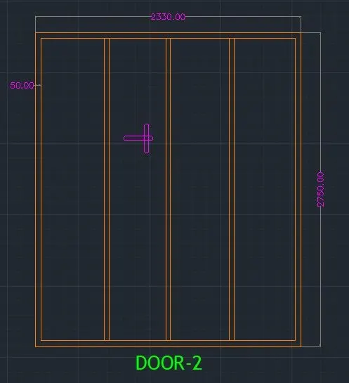
- Door-2 – 2330 x 2750 mm
PROCEDURE
Door-1 -2330 x 250 mm:
Create a rectangle of size 2330 x 2750mm
Offset 50mm as a frame 90mm for the left side, Explode the rectangle
By divide ‘ DIV’ divide the top line into 4 segments from the division point draw lines vertically to divide it into shutters.
Offset 25mm on both sides for the thickness, delete the centre line.
Create a rectangle to show the panels. Offset 20mm from the 1st rectangle & offset 100mm from the 2nd rectangle. Draw lines joining the corners of the outside & inside rectangle.
Create the panel as a block, so that it is easy to copy, create lock by rectangle
Command, and fillet the corners with radius 5mm.
By using the copy all the frames are copied.
Layer is created & all the objects are kept in different layers.
Creating block:
Command: B – give name as door-1 > pick point > select corner point > select object > select the full object > OK. Select scale uniformly & allow exploding.
Door-2 -2330 x 250 mm:
Create a rectangle of size 2330 x 2750mm
Offset 50mm as a frame 90mm for the left side, Explode the rectangle
By divide ‘ DIV’ divide the top line into 4 segments from the division point draw lines vertically to divide it into shutters. To make the points visible, command ‘ DDPTYPE ‘ select the style of point.
Offset 25mm on both sides for the thickness, delete the centre line.
create lock by rectangle
Command, and fillet the corners with radius 5mm.
Layer is created & all the objects are kept in different layers.
Creating block:
Command: B – pick a corner point > select the whole door > tick the box of scale uniformly > explode.
3). Aim: To Create Electrical Legends
- Create each electrical symbol
- Creating them as block
- Arranging them in legends
PROCEDURE
Create Each Electrical Symbol:
- Single gang switch: Draw a circle of radius 64mm & with line vertical & horizontal line perpendicular to the inclined as required.
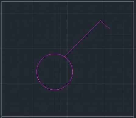
- Double gang switch: Draw circle & draw two horizontal lines & a vertical incline line.
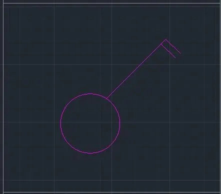
- Triple gang switch: Draw circle & draw 1 vertical incline line. Three horizontal lines.
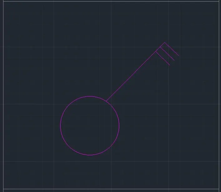
- Single two way switch: Draw same as single gang switch & with donut command give internal dia as zero & for external diameter select it in circle.
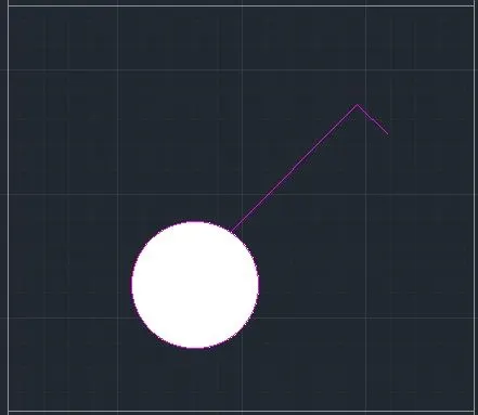
- Double two wat switch: Draw same as double gang switch & create donut.
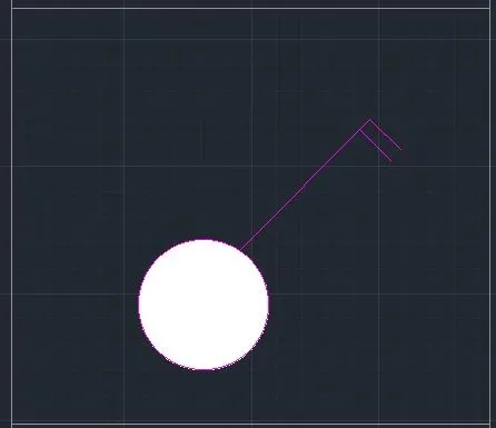
- Triple two way switch: Draw same as triple gang switch & create donut.
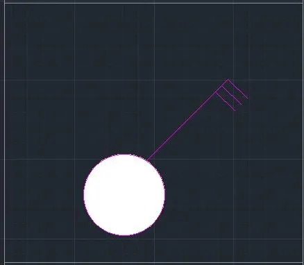
- Switch cross: Create a circle & donut inside & with line command draw an inclined vertical & perpendicular horizontal. Mirror the line in both directions.
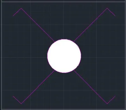
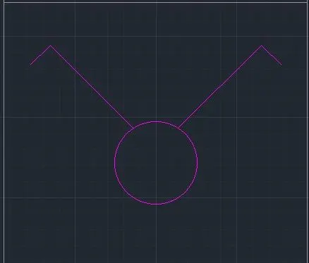
- Switch serial: Copy the switch cross & delete two bottom lines, remove the donut also.
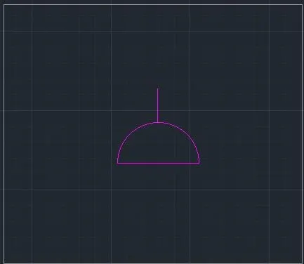
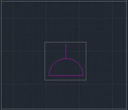
- Single socket: Create a circle, divide it into half & draw a line at the top.
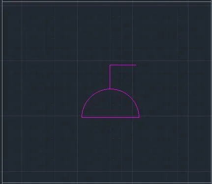
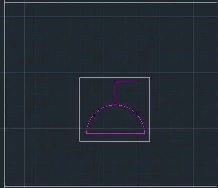
- Single socket for lamp: From the single socket, draw a horizontal line perpendicular to vertical.
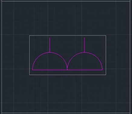
- Double socket: Draw the single socket & copy it to create same & place it using snap on.
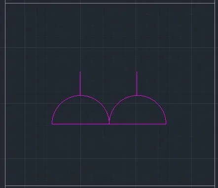
- Floor socket single: Draw a rectangle surrounding single socket.
- Floor single socket for lamp: Draw a rectangle surrounding single socket for lamp.
- Floor socket double: Create two single socket & place a rectangle surrounding it.
- Floor socket single telephone: Draw a single socket, a triangle & surrounded by a rectangle.
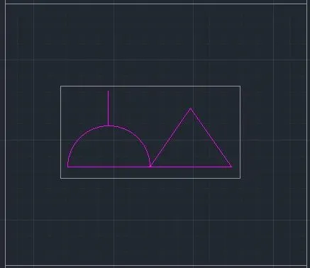
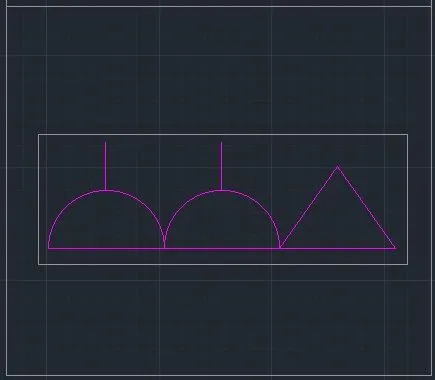
- Floor socket double, telephone: Draw 2 single socket & a triangle surrounded by a rectangle.
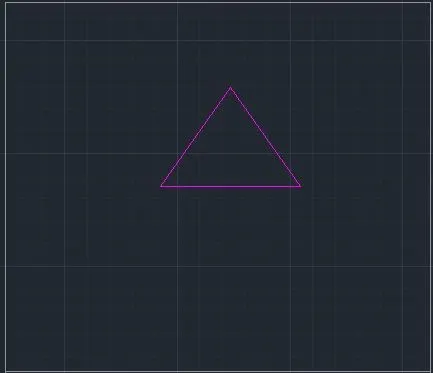
- Telephone socket: Draw a triangle.
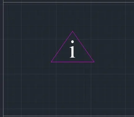
- Internet socket: Insert text ‘’ I ‘’ in the triangle.
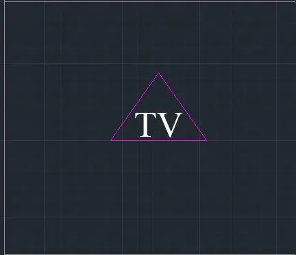
- TV socket: Insert text ‘’ TV ‘’ in the triangle.
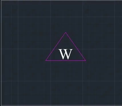
- Weatherproof socket: Insert text ‘’ W ‘’ in the triangle.
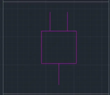
- Duct base section: Draw a rectangle – select the bottom grip point – select add vertex – them pull the vertex to create a bend, with line draw the lines.
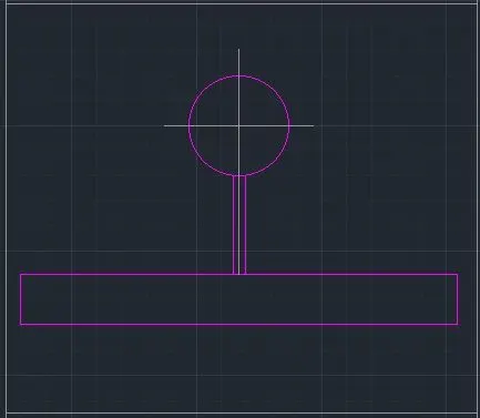
- Wall bracket: With rectangle draw the base, create a circle a circle, draw a line connecting the rectangle & circle, draw a cross line inside the circle.
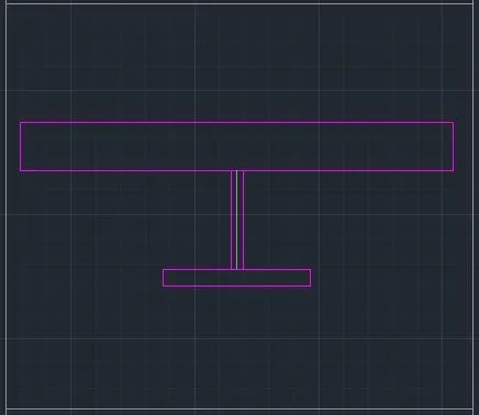
- Picture lamp: Draw two rectangles connected by a line.
Creating them as block:
Command: B – give name as single gang switch > pick a point > select object > tick scale uniformly & allow exploding options.
Similarly define each one of them as block giving the respective names. Do the same procedure for the remaining symbols.
Creating & Arranging them in legends:
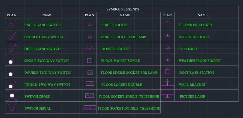
First create a rectangle table having 10 rows & 6 columns.
Place each of the blocks in the respective rows & columns.
To enter text with the block from the insert tab – select object – select block.
Eg. For single gang switch – select from the field – select uppercase in format.
Place the text in the respective rows give text height to 150. Similarly place all the title inside the legends.
4). Aim: to draw the doors of residential project & create it as block.
- D1
- D2
- D3
- D4
- D5
- D6
PROCUDURE:
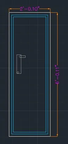
- D1 – 2’ 10’’ x 6’ 11’’:
Draw rectangle with dimension 2’ 10’’ & 6’ 11’’. Draw offset 1.5’’ for frame draw offset 1’’ for shutter.
Draw lock by two rectangles perpendicular to each other & fillet the corners with radius 0.1’’ & circle, write text by multiline text ‘’ D1’’.
Create it as block ‘B’ > give names as type > D1 – pick a corner point > select the object then block is created.
- D2 – 3’ 4’’ x 6’ 11’’:
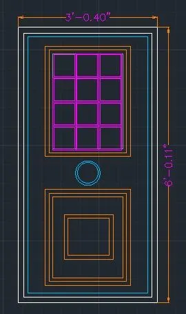
Draw rectangle with dimension 3’4’’ & 6’11’’, draw offset 1.5’’ for frame, draw offset 1’’ for shutter.
Draw rectangle for panel 1’ 11’’ & 2’ 9.1’’, then 1’’ two times, draw a rectangle 5.4’’ x 5.7’’, offset 0.3’’.
Copy it with copy command ‘ CO’ > select mode > select the rectangle > select array > enter no: of array as 3 > place it as required, copy the 3 rectangles to 4 rows.
For the second panel draw a rectangle of 1’ 11’’ x 2’ 0.6’’, offset 1’’ 3 times draw another rectangle inside this of 1’ 0.8’’ x 1’ 1.2’’ & offset 1’’.
Draw lock by circle in b/w the two panels, write text by multiline text ‘ D2’.
Create it as block ‘ B’ > give name as type-D2 > pick a corner point > select the object, then block is created.
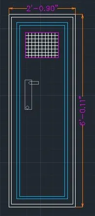
- D3 – 2’ 9’’ x 6’ 11’’:
Draw a rectangle of 2’ 9’’ x 6’ 11’’.
Offset 1’’ for thickness, 2’’ offset for frame. 1’’ thickness, offset 1.5’’ as shutter thickness.
Draw a rectangle at the top for ventilation 1’ 3’’ x 9’ 3’’, give offset 1’’ for thickness, hatch inside the rectangle.
Create lock by rectangle two of them, perpendicular to each other & a circle.
Create it as a block command: B > give name as type D3 > pick point > select object > tick scale uniformly & explode all.
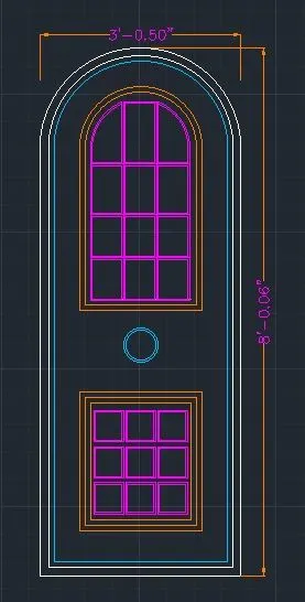
- D4 – 3’ 9’’ x 8’ 7’’:
Draw rectangle REC of dimension 3’ 9’’ x 6’ 10’’, explode it & create an arc with 2 > point method with both point as the endpoints, offset the arc & the line with 1.5’’ & then 1’’.
Offset 8’’ from arc & rectangle for panel & divide it into two, take 1’’ offset 2 times to show the thickness on top figure & bottom rectangle, create rectangles inside the panel.
For lock, create a circle, make it a block, name as type D4 > pick a point & select the object tick the dialogue box of uniform scale & explode all.
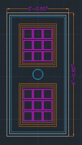
- D5 – 3’ 5’’ x 6’ 8’’:
Draw a rectangle of 3’ 5’’ x 6’ 8’’, offset 1.5’’ for frame offset 1’’ as shutter thickness, create another rectangle inside with offset 4.4’’.
Create another rectangle on the bottom 2’ 2.9’’ x 2’ 2.6’’, offset 1’’ two times for both rectangles.
Create rectangle inside for panels with offset 0.5’’, copy it for 3 columns & 4 rows, similarly copy it in bottom rectangle for 3 rows & 3 columns.
Create it as block command: B > give name as type D5 > pick point > select object > tick scale uniformly & explode all.
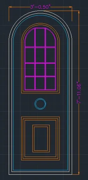
- D6 – 3’ 5’’ x 7’ 11.6’’:
Draw rectangle REC of dimension 3’ 5’’ x 7’ 11.6’’, Explode it & create an arc with 2 point method with both point as the endpoints, offset the arc & the line with 1.5’’ & then 1’’ for frame.
Offset 8’’ from arc & rectangle for panel & divide it into two, take 1’’ offset 2 times to show the thickness on top figure & bottom rectangle, create rectangles inside the top panel, 3 row & 4 columns.
For bottom panel, offset the rectangles by 1’’ 3 time as & 3.3’’ & again 1’’, for lock create a circle.
Make it a block, name as type D6 > pick a point & select the object tick the dialogue box of uniform scale & explode all.
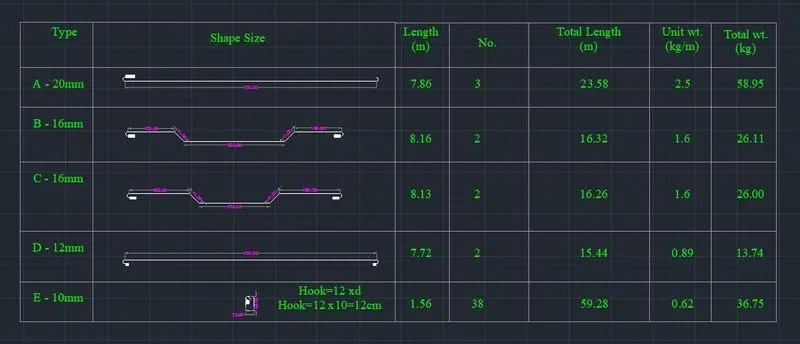
5). Aim: To Create bar bending schedule & insert it as block.
- Drawing each shape
- Creating it as block
- Inserting it in table as Bar Bending Schedule.
PROCEDURE:
- Drawing each shape:
A-20 mm
Draw a line of 750 cm for straight bar create arc for the bend, create on one side & mirror it on another side.
B-16 mm
Draw line of 300 mm for straight bar, draw vertical line of 41 cm & extend a horizonatal line & draw a line included at 45 degree from the base of vertical line up to horizontal line.
Trim off the unwanted lines, copy the same on the other side, draw a horizontal line of 139 cm & copy it on other side, draw bend with arc & mirror the same on other side.
C-16 mm
Draw a line of 210 cm, draw vertical line of 41 cm & extend a horizontal line & draw a line inclined at 45 degree from the base of vertical line up to horizontal line.
Trim off the unwanted lines, copy the same on the other side, draw a horizontal line of 180 cm & copy it on other side. Draw bend with arc & mirror the same on other side.
D-12 mm
Draw a line of 750 cm for straight bar, draw an arc downwards, mirror it on the other side.
E-10 mm
Draw a rectangle of 23 cm & 43 cm, fillet the corner with fillet radius 5 cm, draw two line of 120 cm.
Create each of them as block by using command: B > give name as A > pick a point > select the object > select delete > tick box of scale uniformly & explode all.
Similarly create 5 blocks: A,B,C,E & insert each of the bars as blocks.
Inserting blocks in the table:
Craete a table with rectangle & divide it into 6 rows & 7 columns, with multiline text enter type, shape size, length, no, total length, unit weight, total weight & all other text, by command ‘ I ‘ insert each of the block in respective columns.
RESULT:
Template is drawn and text and attributes are inserted.
Doors of warehouse are drawn and placed it in blocks.
Electrical legends are created and it is made into blocks.
Different types of door for residential project are drawn and are placed in blocks.
Bars are drawn and made it as blocks and inserted it in table as bar bending schedule.