Creating Architectural and Structural model with 3D rendering using REVIT
ANSWER:
Aim:-
To create a architectural and structural model with 3D rendering using with Revit tool.
Introduction:-
In this project we are going to see about how to create a architectural and structural model with 3D rendering also for using the revit software. In this project I can choose the Multi-unit residential appartment building. Take the reasonable assumption for geographic ans location of our project. The assumption are matching with the NBC rules. Use the structural model to load the components like foundation, column, beam, flooring, floor opening for elevation and structure. In the architectural components to add walls with fancy finising and interior partition walls and etc,. Then sheet settings for floor plan with annotation, Elevation and sections also. Then we going to do a render process of interior rooms, out showing topographic feature and structural framing. Finally prit the set of drawing sheet sets and submit the drawings to the architectural and structural model.
Procedure:-
Step - 1:- Select the structure type:
- I can choose the Multi-story appartment buildings.
Step - 2:- Assume the assumption requirements for NBC requirements:
- On my project building height was 13m. It's comes under the NBC norms.
- The building area also greater than 40 sq.m.
- On room sizes alo greater than 15.5 sq.m.
- The interior and exterior wall height of all rooms is 3m. and the NBC norms minimum height was 2.1m.
- The wall thickness was exterior 200mm and partition wall is 150mm. it's applicable for the NBC norms.
- The passage way was 6m upto 75m length.
Step - 3:- Structural Model:
a. Foundation:-
- We already have the comined gridlines of architectural and structural model.
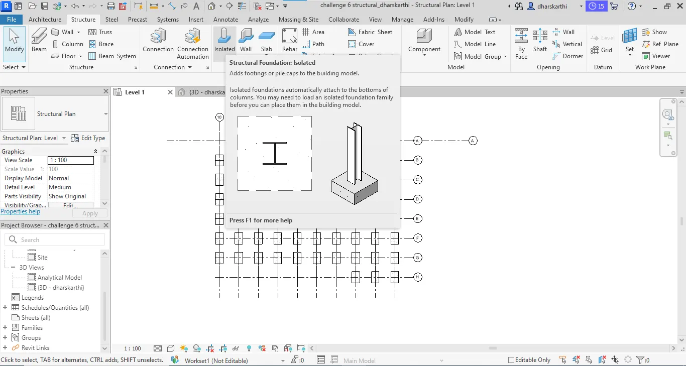
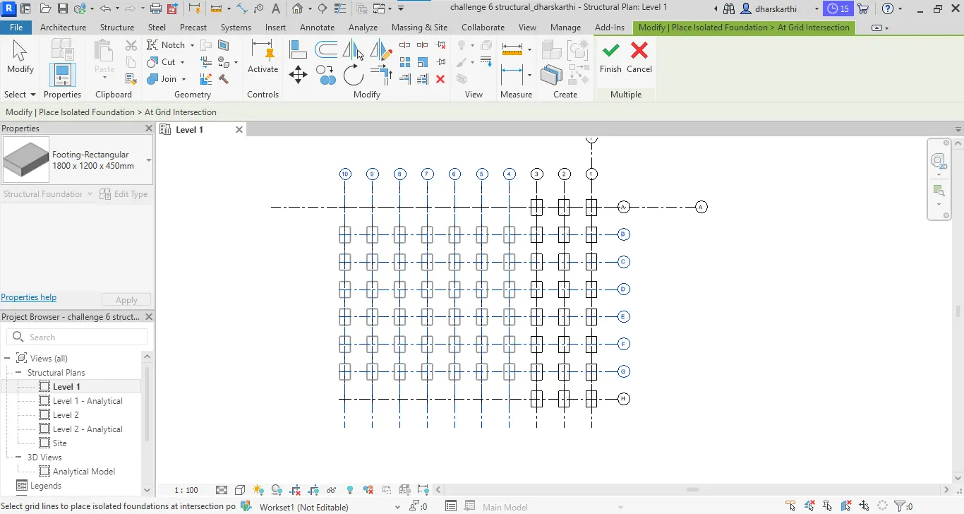
- We choose the structural model then select the Isolated footing tool then place it on all grid intersection points then finish it.
b. Columns:-
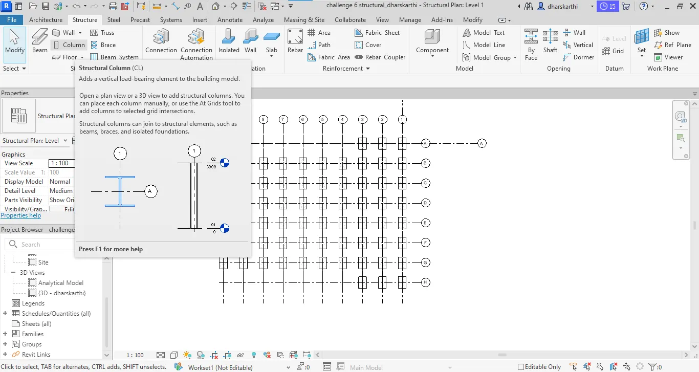
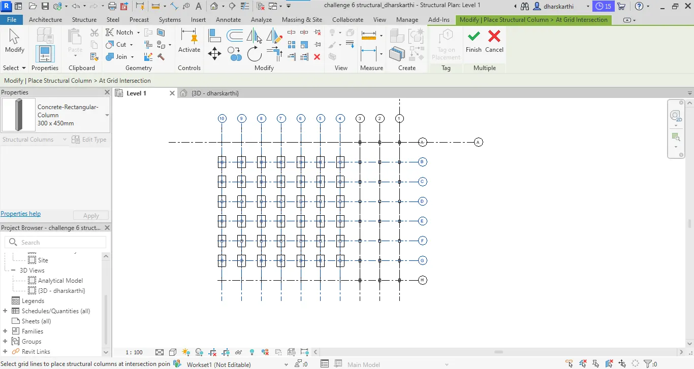
- Select the Structural column tool then choose at grid option then select the multiple intersection point of all grid lines then finish it and place the columns.
c. Beams Connected to columns:-
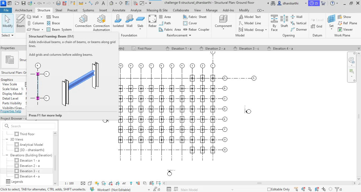
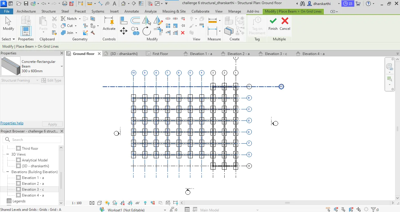
- Select structural beam option then choose at grid option then select all the connected grid lines then finish it to place all the beams.
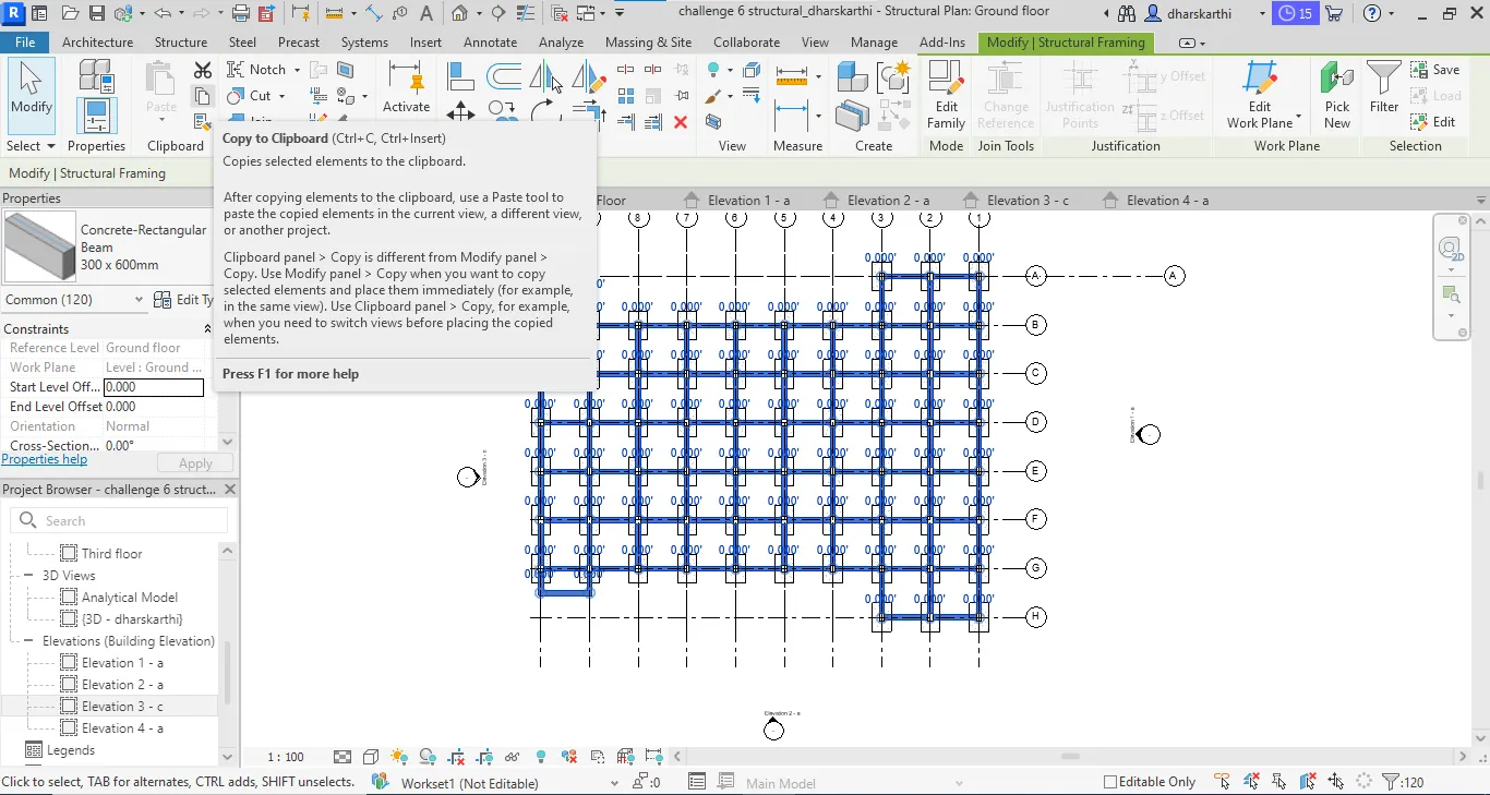
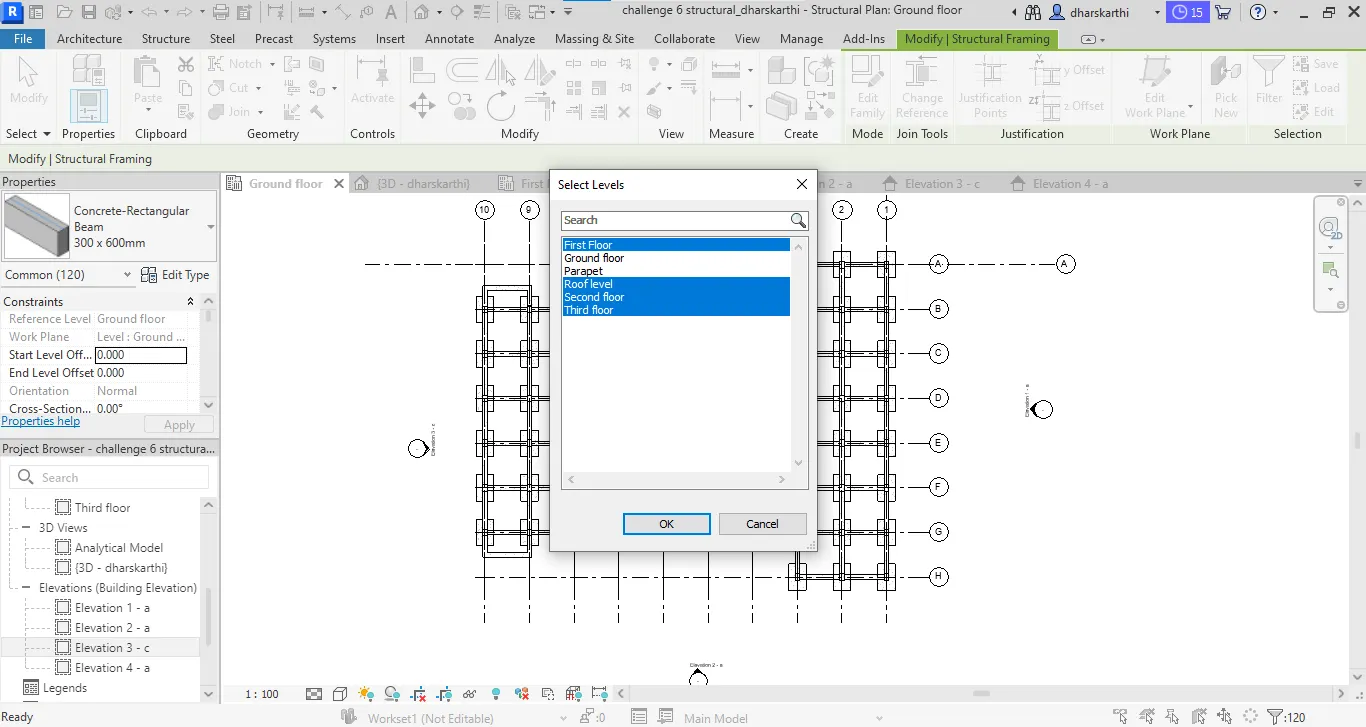
- Select all the columns and beams then copy to clipboard then paste it to alligned levels then select the levels and paste it to create a stucture of a building.
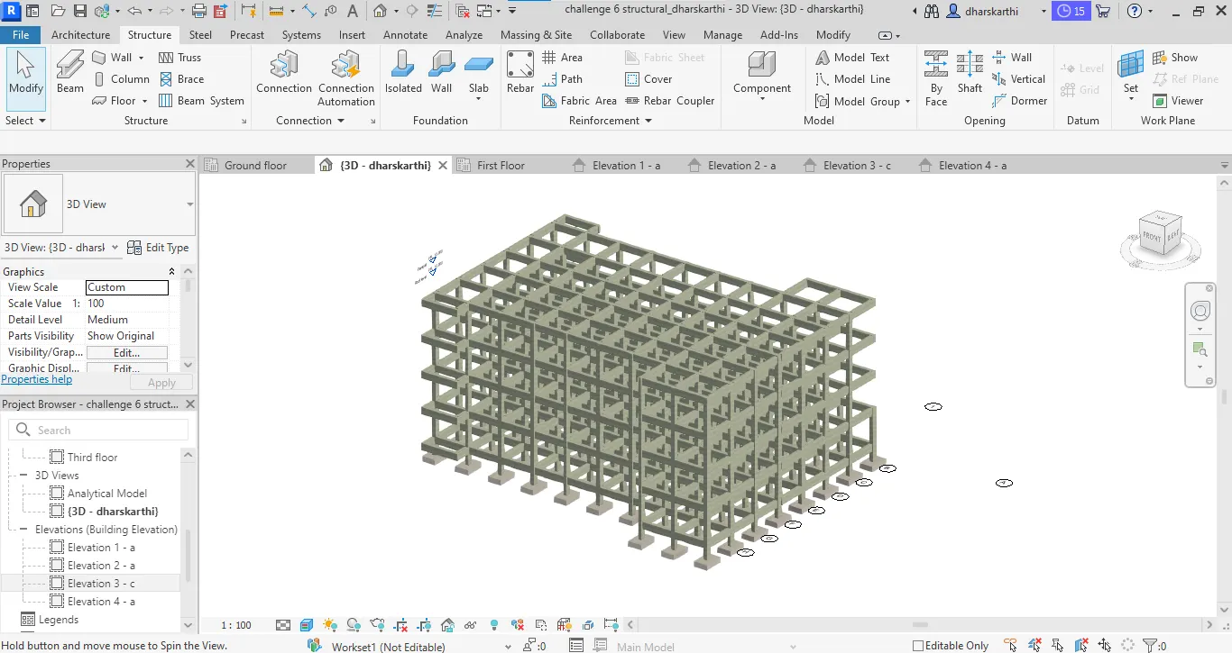
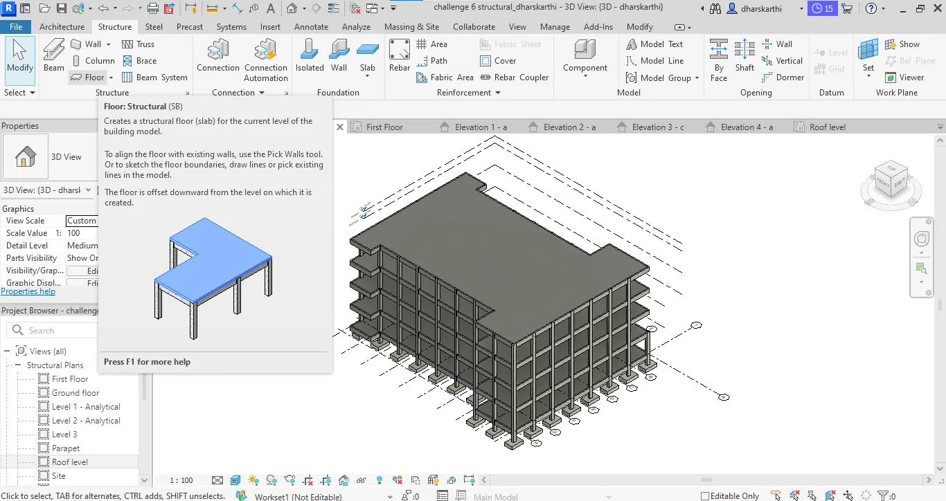
d. Floor or decks:
- Selec the structural floor option then choose the pick line or draw line tool to draw a floor boundarys then finish it. the floor was created.
- Then copy to clipboard the floor and paste it to alligned levels then place it to all other floors.
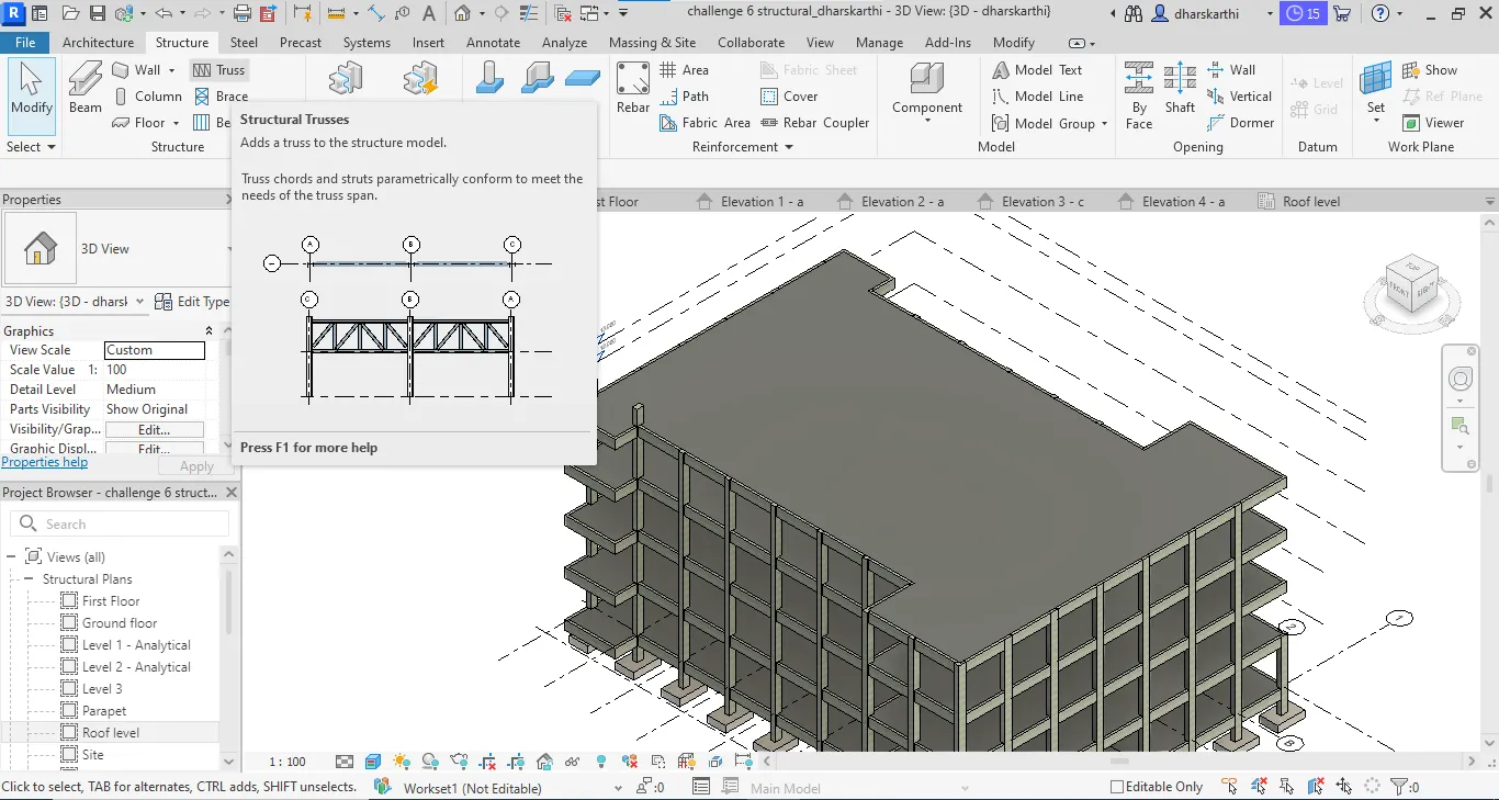
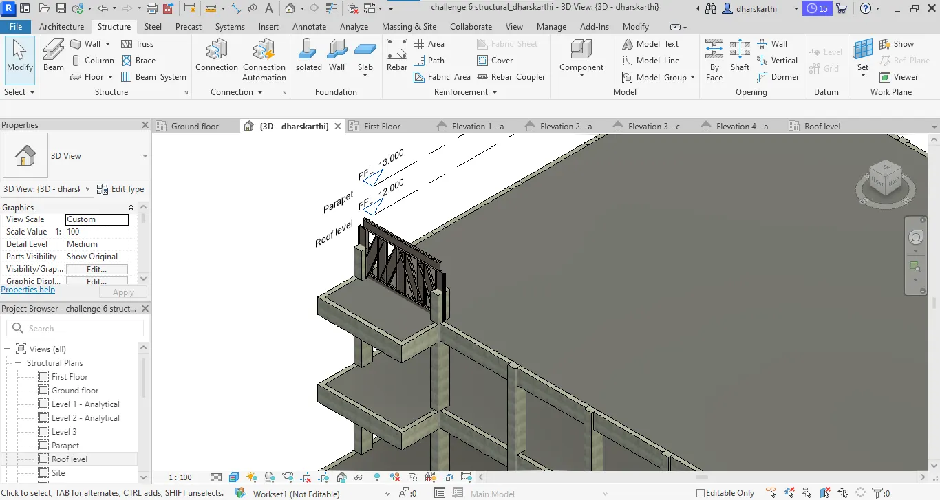
e. Roof framing/Truss:
- Select the truss option then choose pick line tool and place the trusses where you want.
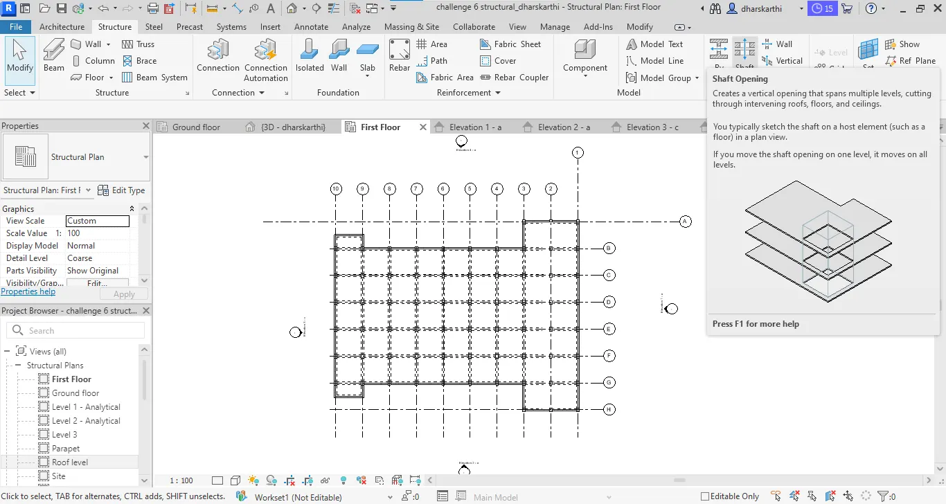
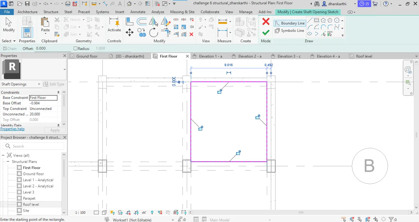
f. Floor openongs for staircase and elevators:-
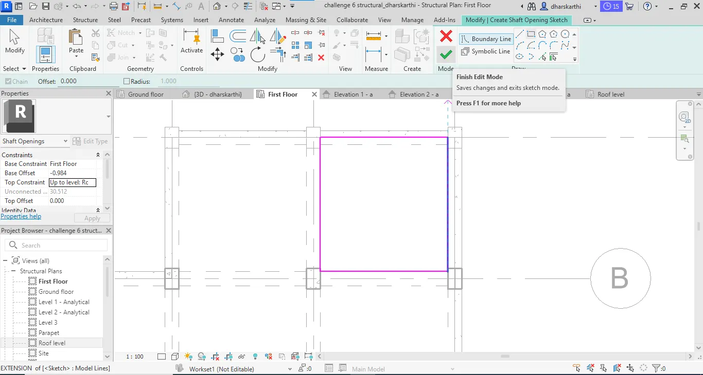
- Go to any structural plan and select the shaft tool then create a shaft opening size and where you want and the base constraint of ground floor 0.00 and the top constraint of the roof level was 0.00.
- Then finish it to created the shaft opening for elevators and staircases.
Step - 4:- Architectural Model:
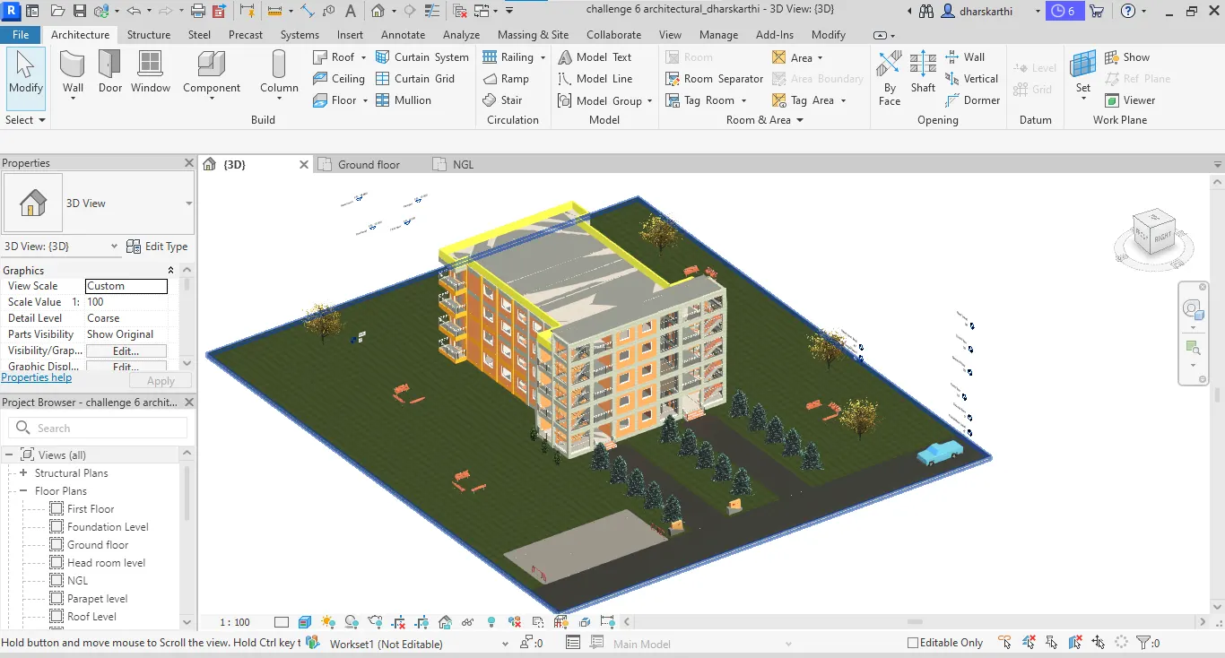
a. Wall layout with appropriate material and finishing:
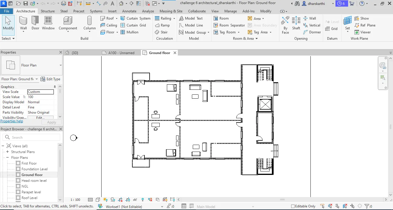
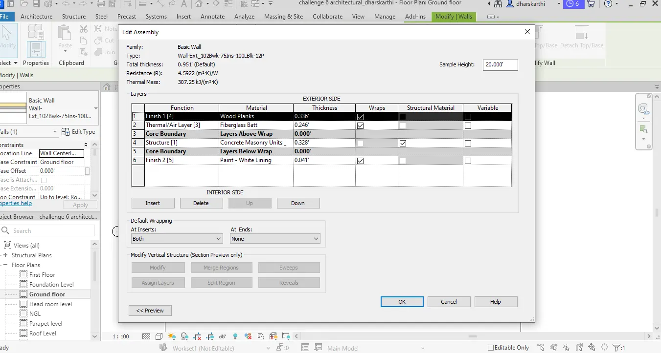
- Open an architectural model then select wall option and draw a walls on appropriate location and goto edit type then edit value of wall thickness, stucture catagery and finishing.
- Make external and internal partion wall of thickness 230mm and 150mm respectively.
b. Exterior facade with fancy finishing:
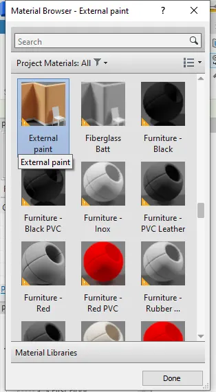
- On the manage tab choose the material browser option and create new material or select the appropriate material and apply it with our ideas then finish it.
- Next goto modify settings and choose paint option then paint and what ypu need then finish it.
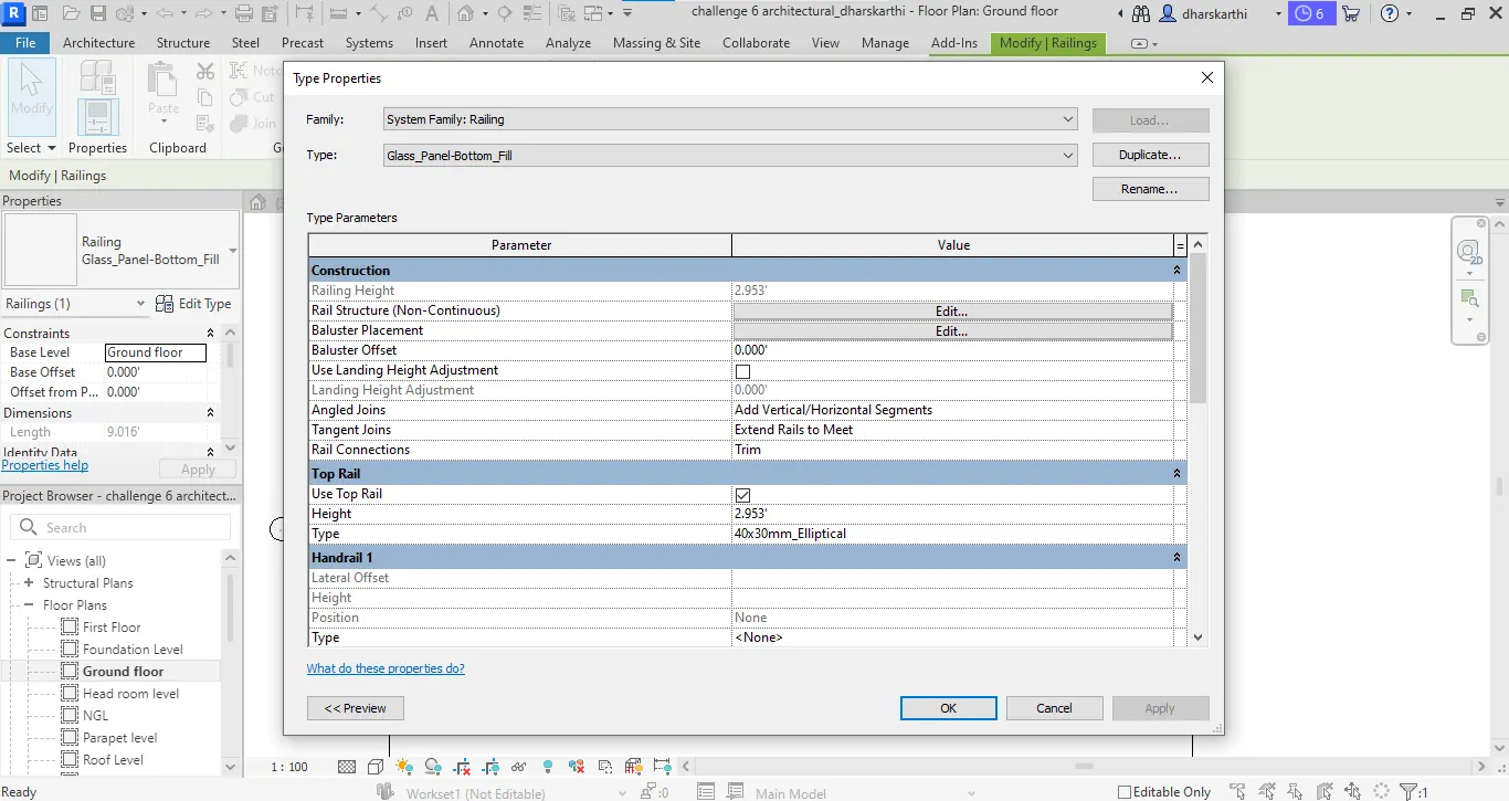
- On the architectural tab we have the option called railling then select it and pick the line where we want and finish it to created the railings.
c. Interior partition walls to size rooms:
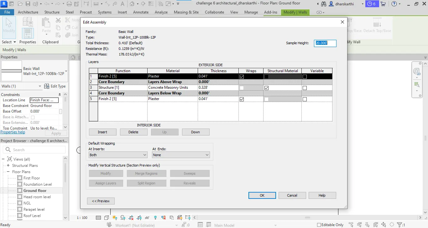
- Select the wall option on the architectural tab and draw a partion wall on the inner side of the floor plans thenseparate the rooms like kitchen, hall, bed room and living room and dinning room also.
d. Components to add details to a room:
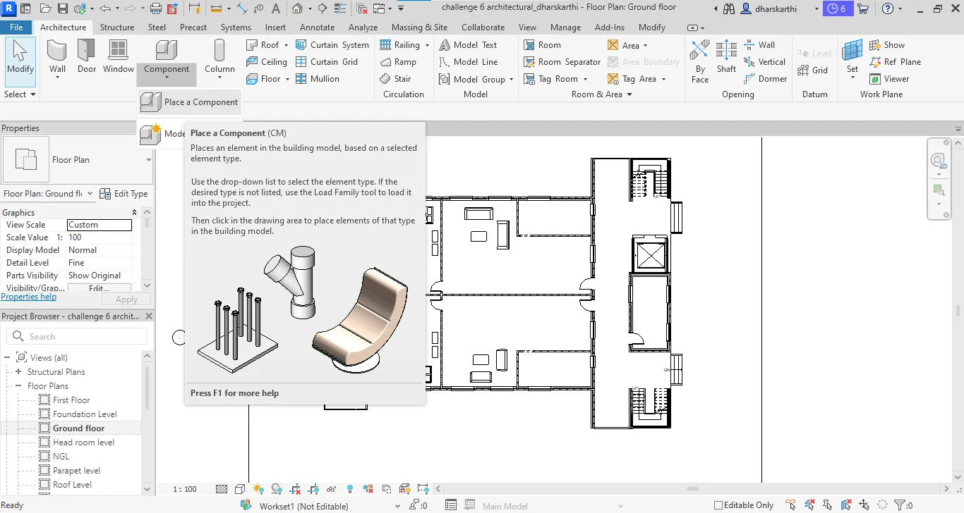
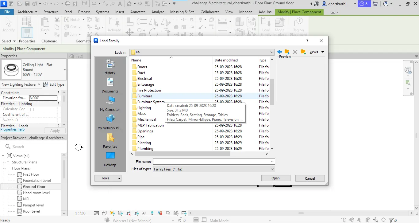
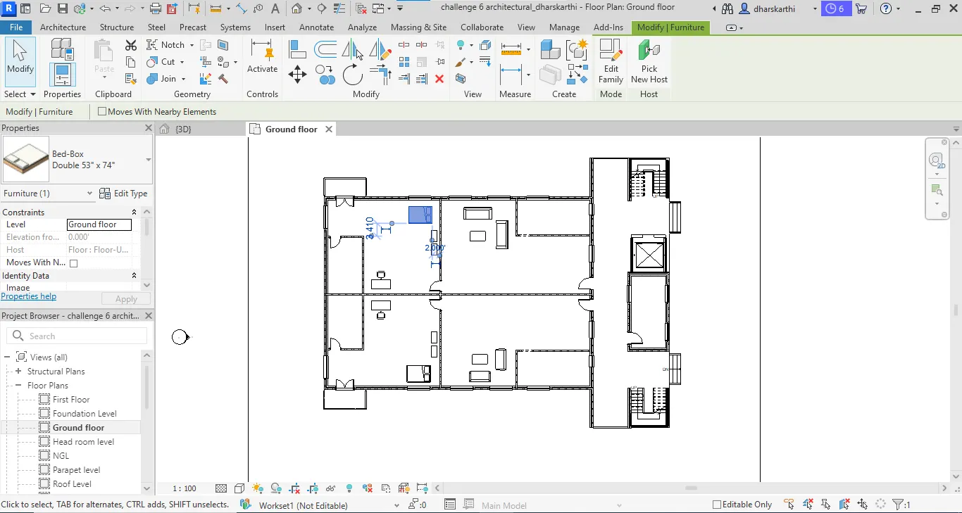
- On the architectural model tab we have the option components and choose place a components option then go to revit librarys and choose the appropriate components and place to where we shown.
- On the door and window tab choose the type of doors and windows what we want and plac eit to the appropriate location.
- Then finish it.
e. Add a components such as stairs and elevators:
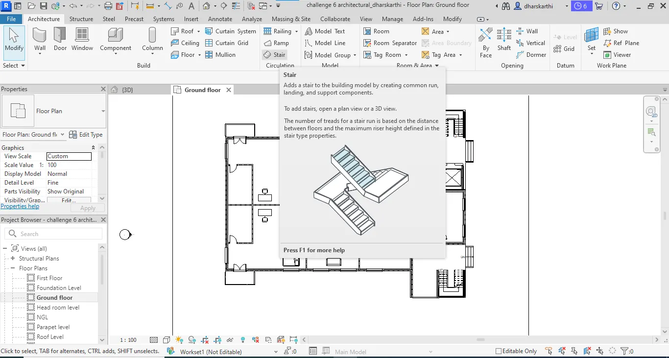
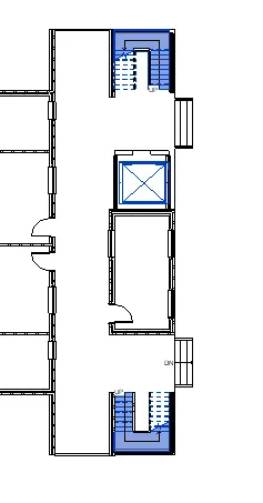
- On the achitectural tab menu choose the stair option and draw a stair on the appropriate location then finish it to the right and left side of the plan.
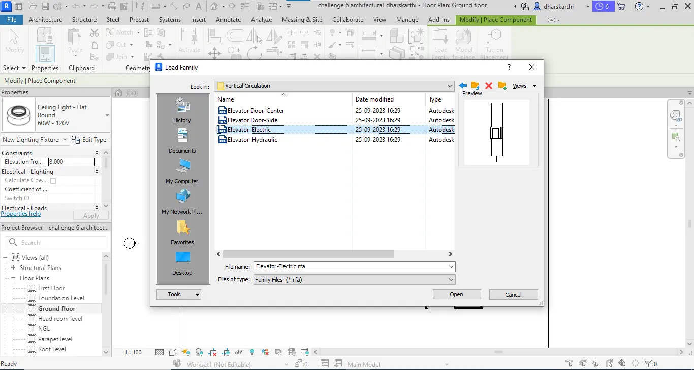
- Then goto components library and choose the electrical elevator and place it where we want then finish it.
f. Curtain walls and glass panels:
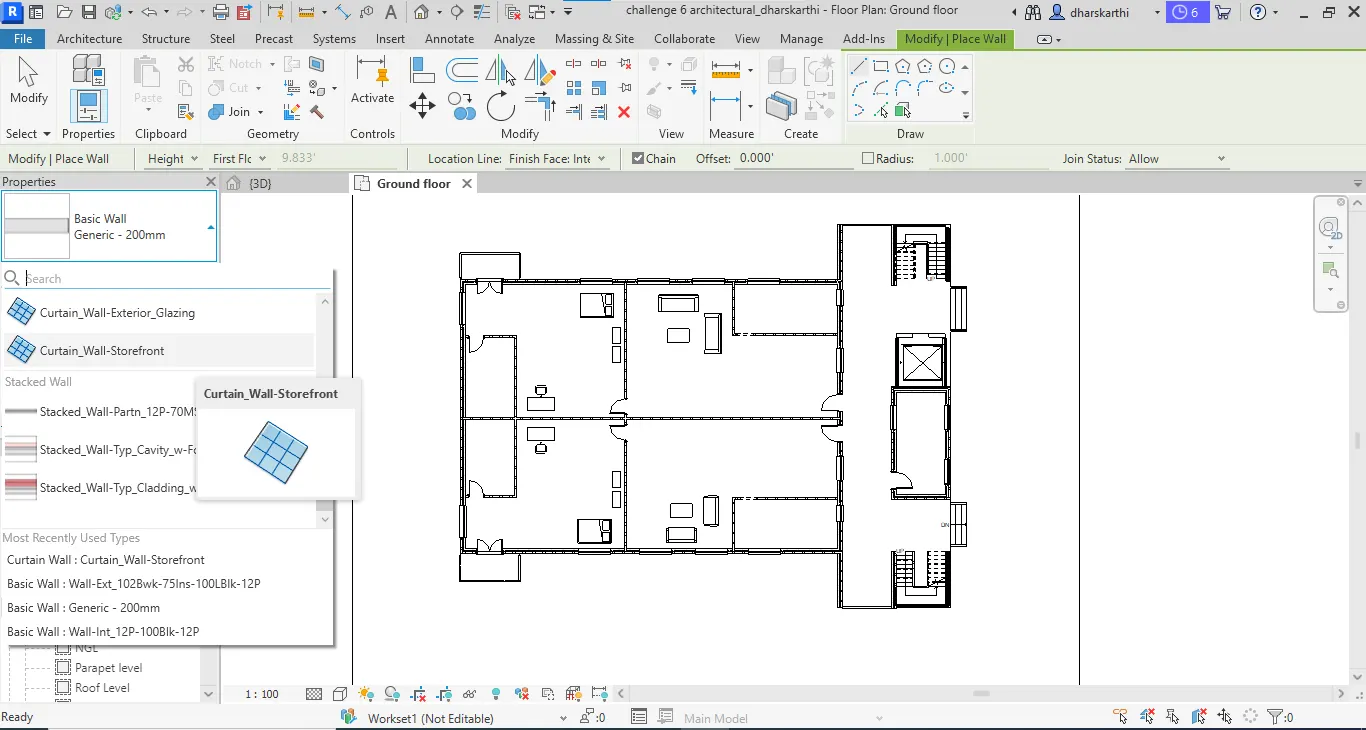
- On the wall tab choose the curtain wall and take a pick line option and select the stairs two outteer sides then the base constraints was ground floor and top constraints was head room level then finish it.
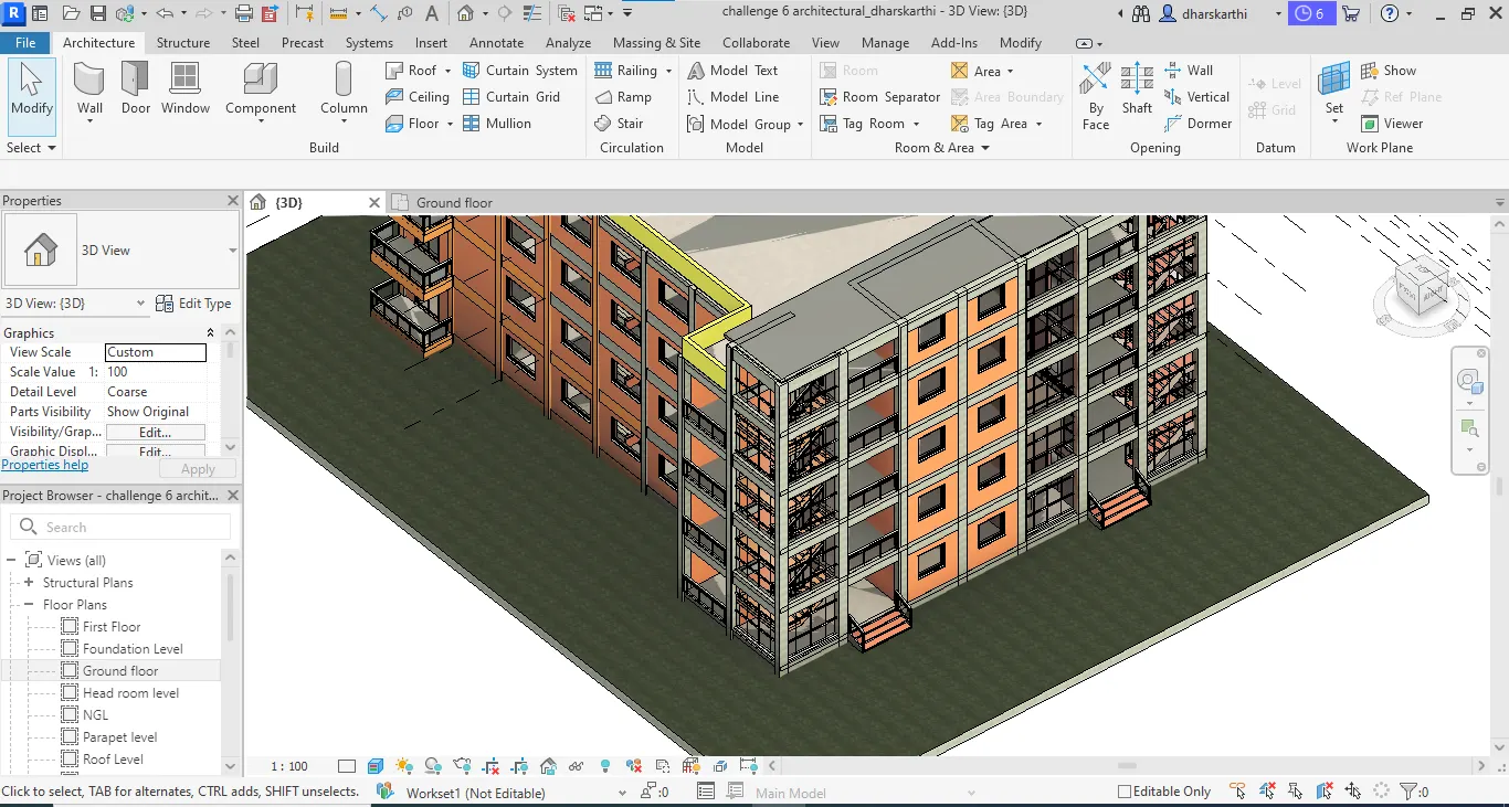
- And the curtain wall appeared like shown in model.
- Then again select the curtain wall and place it with outer face of the Elevator upto Head room level.
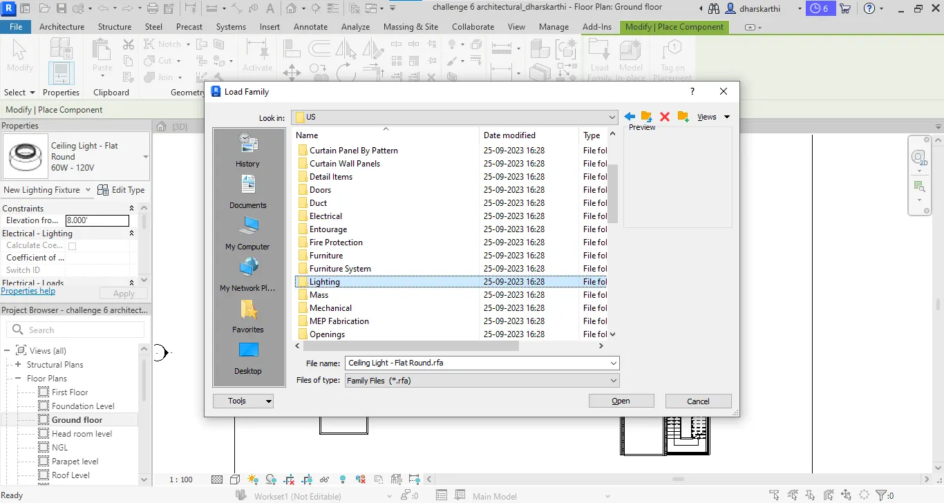
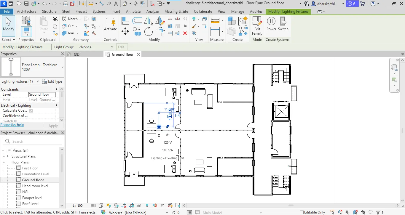
g. Include interior and exterior lightning fixtures:
- On the components tool option goto the revit librarys and select the lightining folder then selec the lights on interior and exterior sides
- then place it with appropriate location.
- Then finish it.
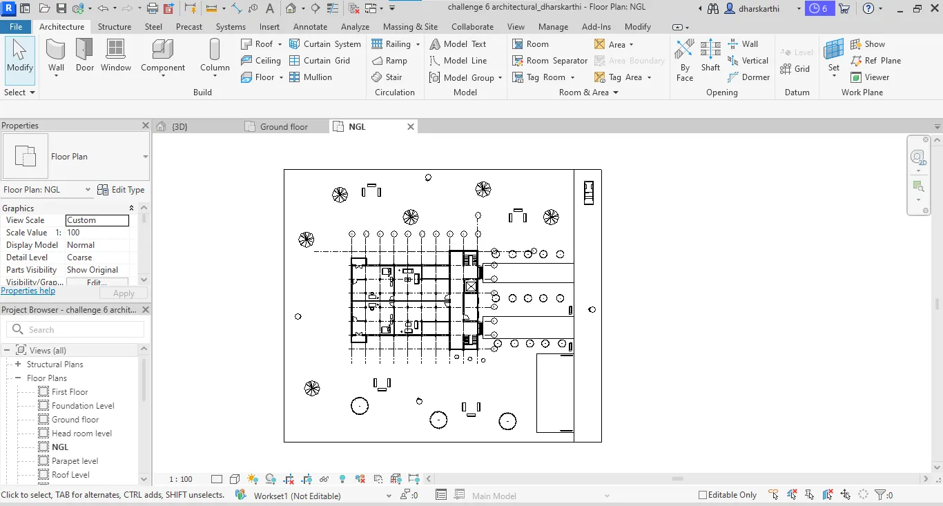
h. Tophographic components:
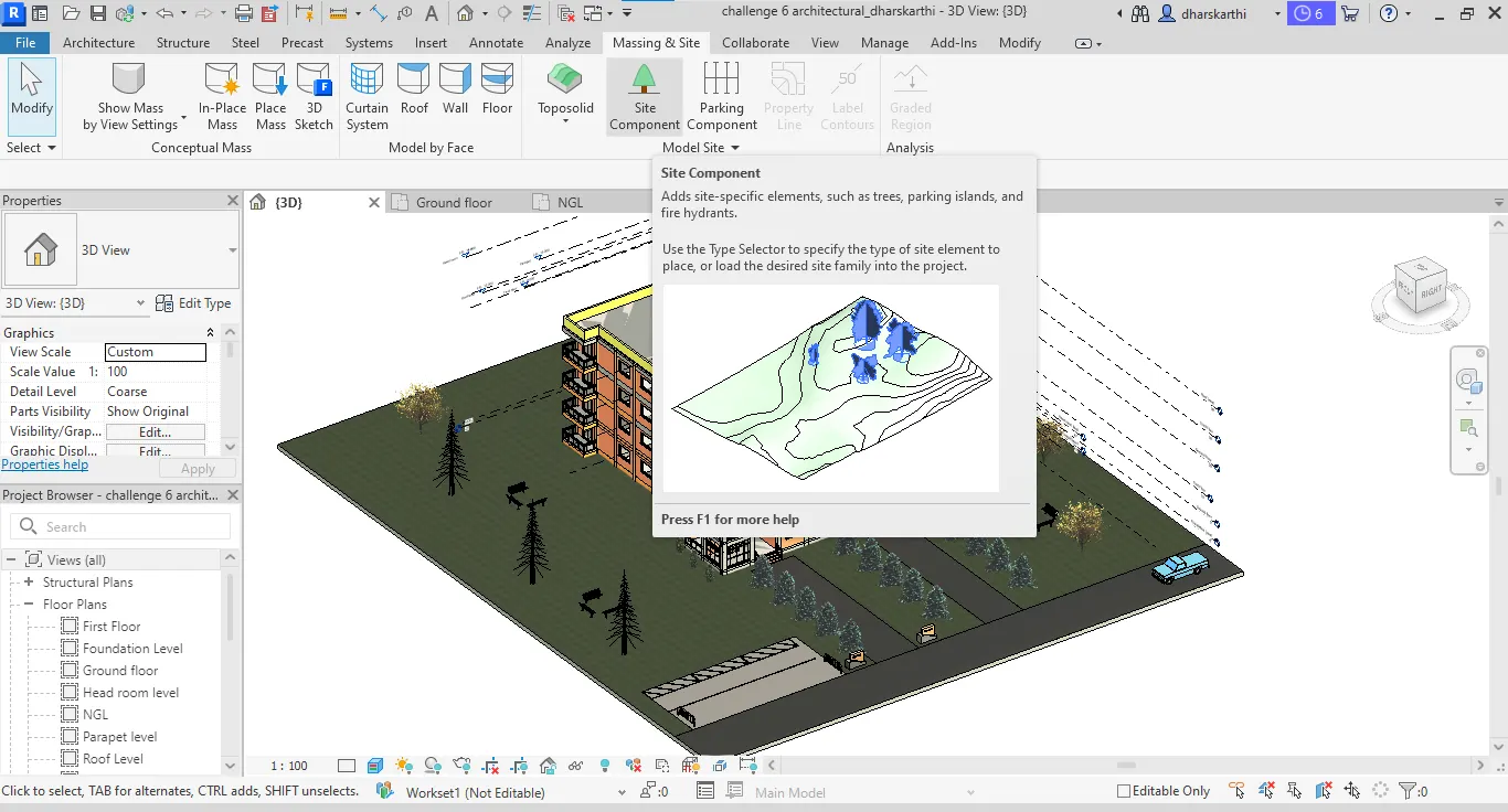
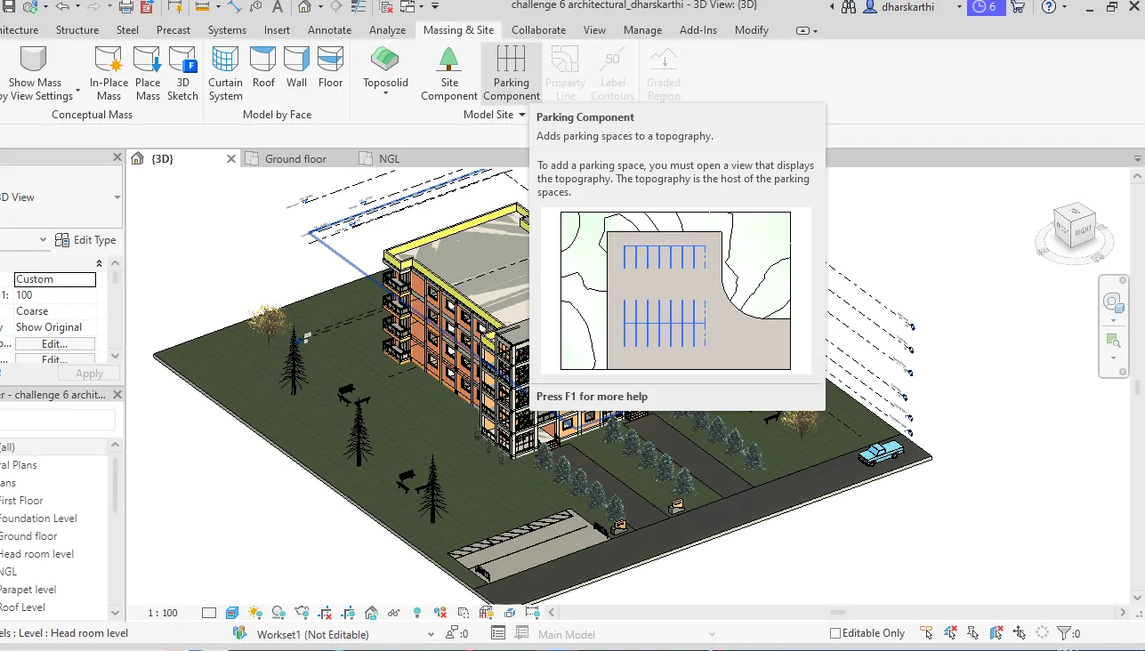
- Goto the massing & site option on top menu bar,
- Then select the site component tool then choose load family option,
- Browse the components on library of planting folder
- Then open it to place the appropriate location.
Step - 5:- Drawing sets:
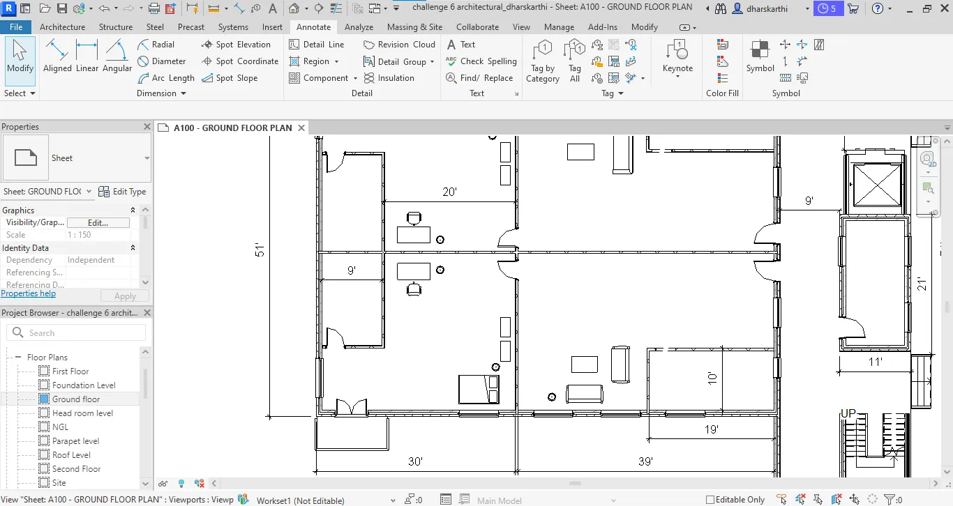
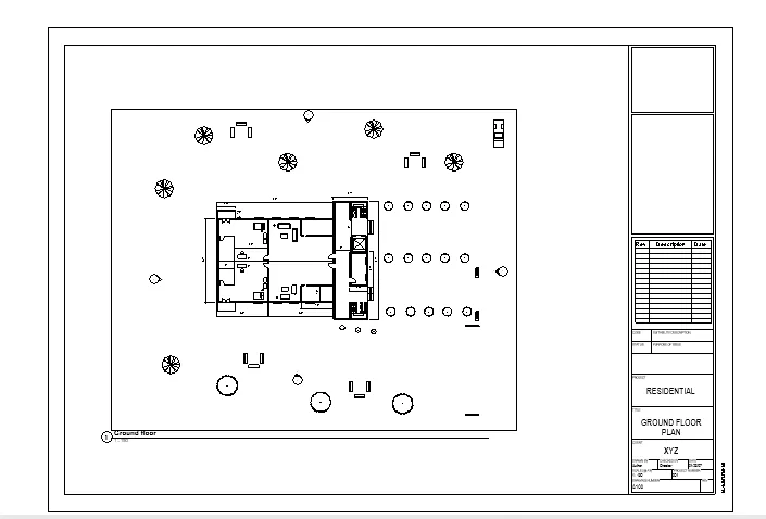
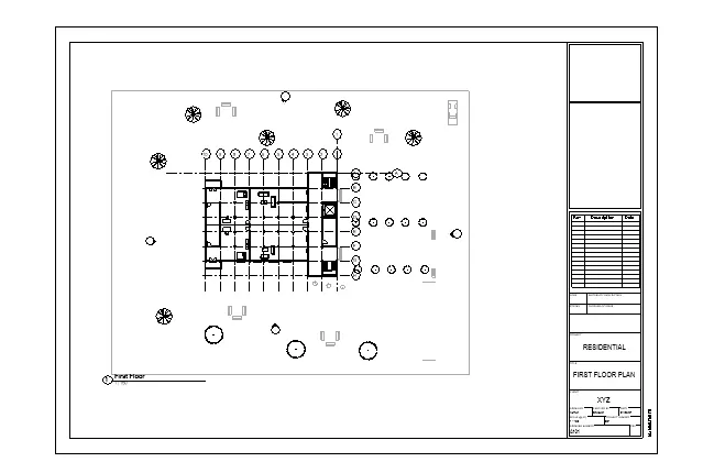
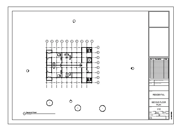
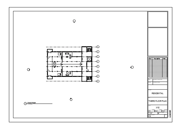
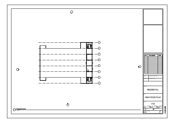
a. Floor plans with annotations:
- Goto the view Tab on the top menu bar then select the Create sheet option then choose
- Then drag and drop the floor plans with annotations on the approproiate sheet sets
- Goto the annotations tab on top menu bar then select the linear or alligned tool then pick the first and last point to show case the annotations.
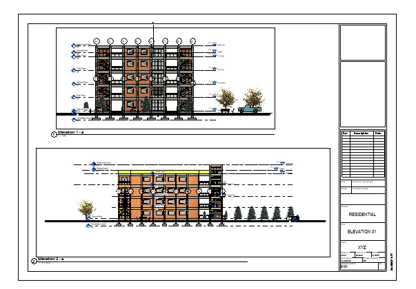
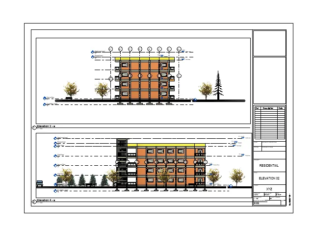
b. Elevations:
- On the view tab select the elevation tool
- Then place the four direction of east, west, north and south dotections.
- Then goto the elevation tab on project browser tab then click the elevation.
- Then Create a new shhet then drag and drop the elevations.
c. Sections:
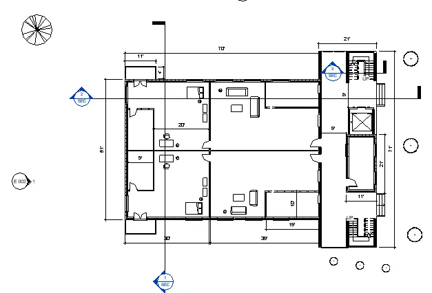
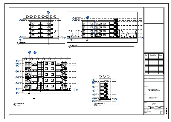
- On the view tab choose the section option.
- Then goto the ground floor plan then draw a section line on where we showcase the detail.
- Next create a new sheet then drag and drop to the sections sheet.
Step - 6:- Render settings:
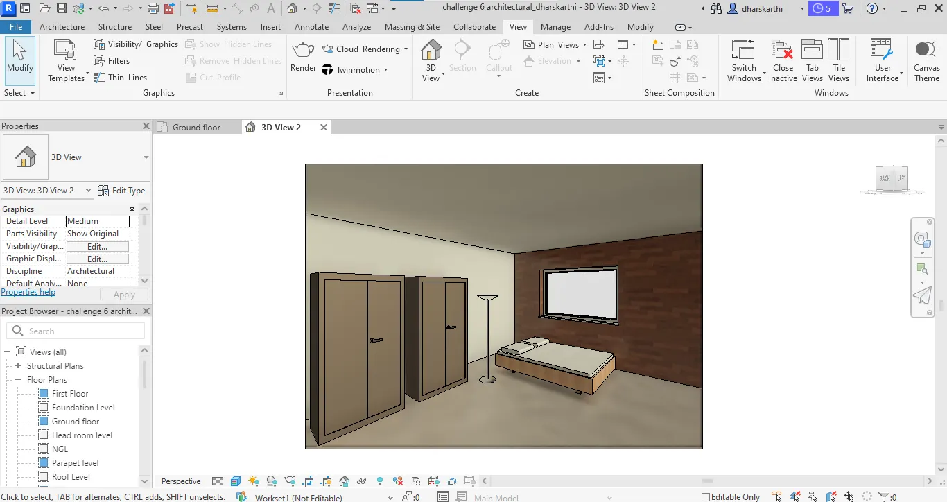
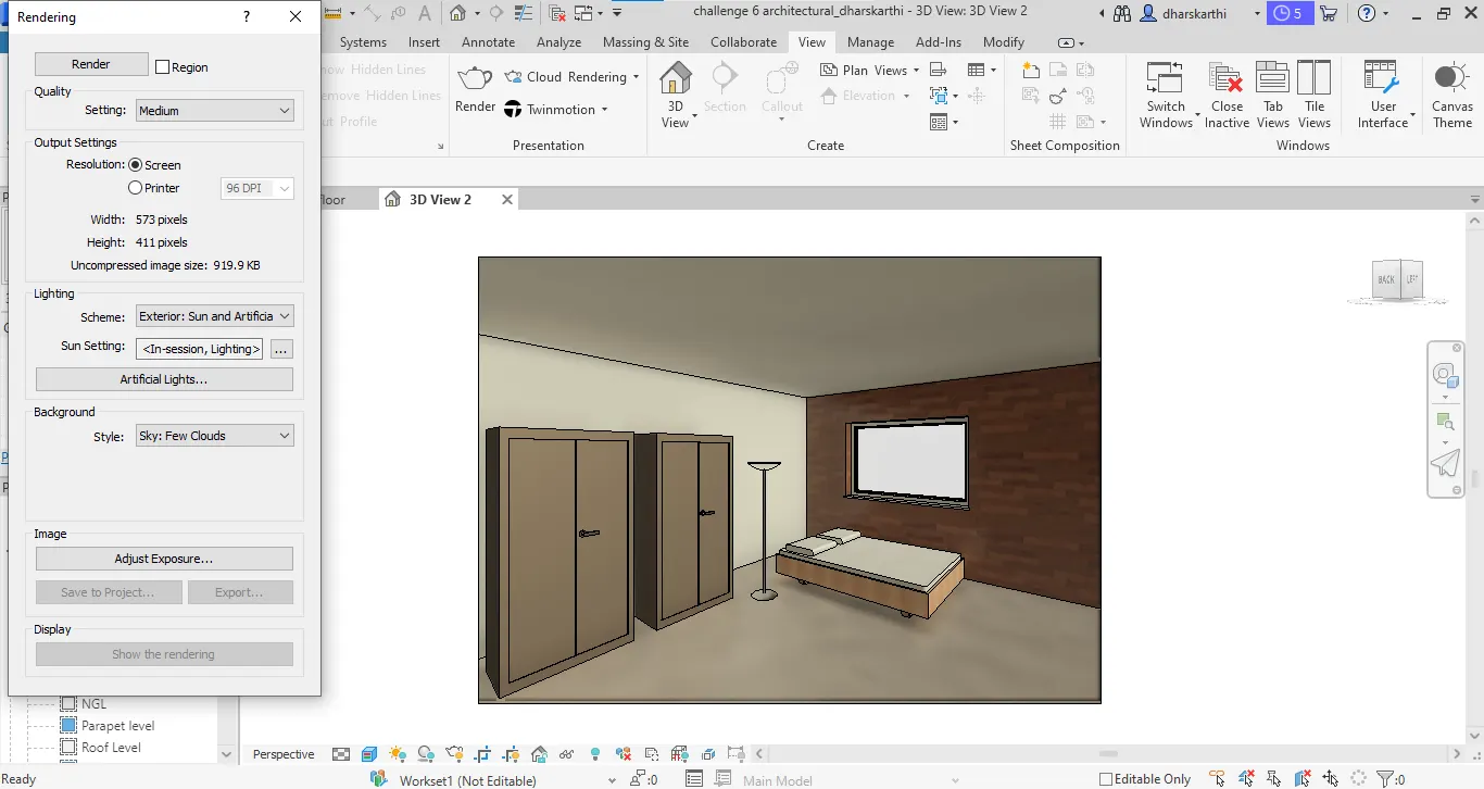
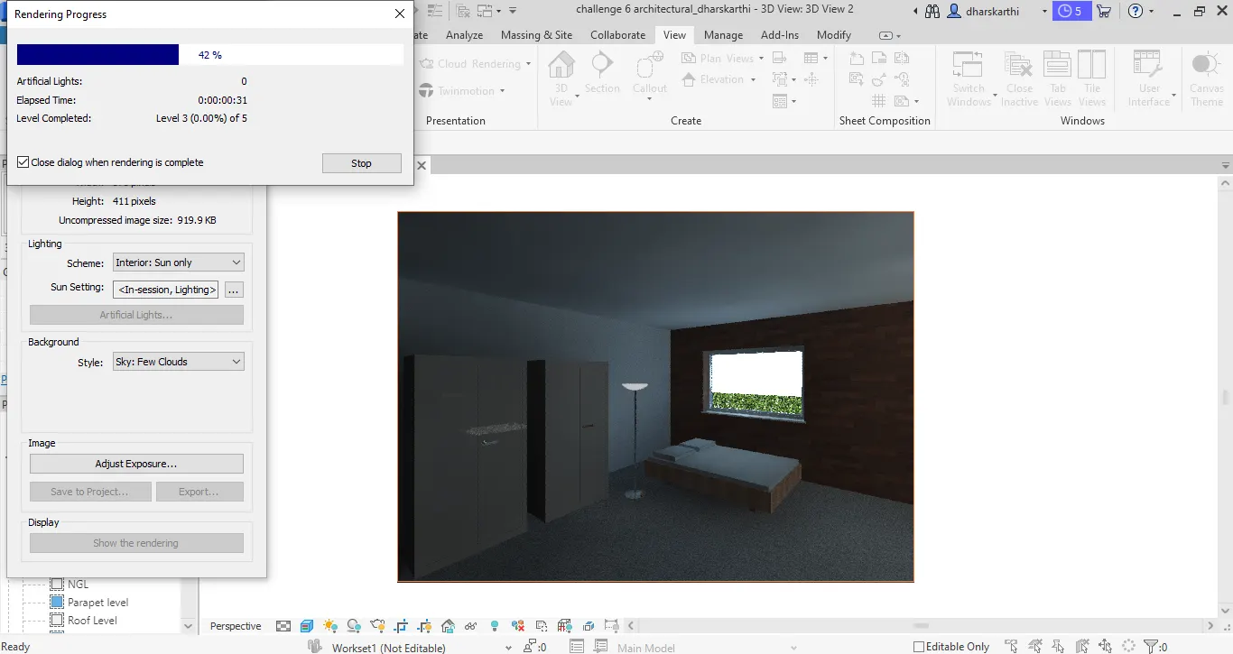
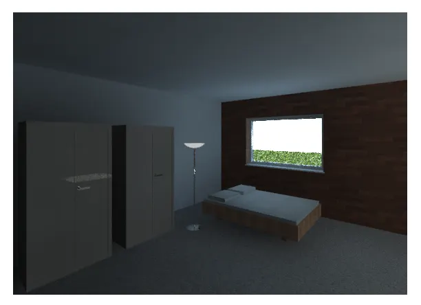
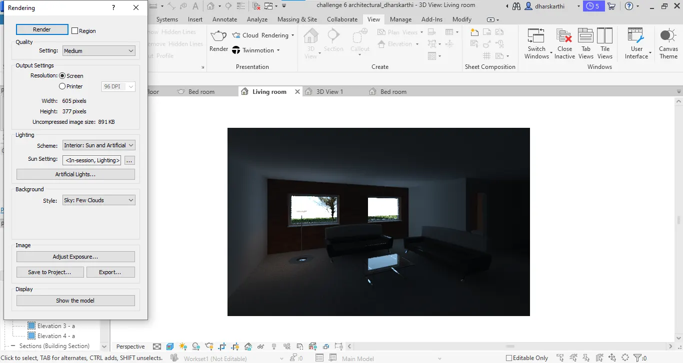
a. Render from interior rooms:
- On the view tab select the camera option.
- Then goto any floor plans then place a camera on the view of interior rooms.
- Next open the camera view then choose the render option and render the views.
- It's showing like the real image of the interior rooms.
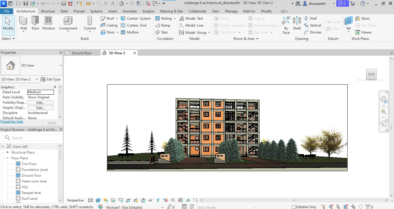
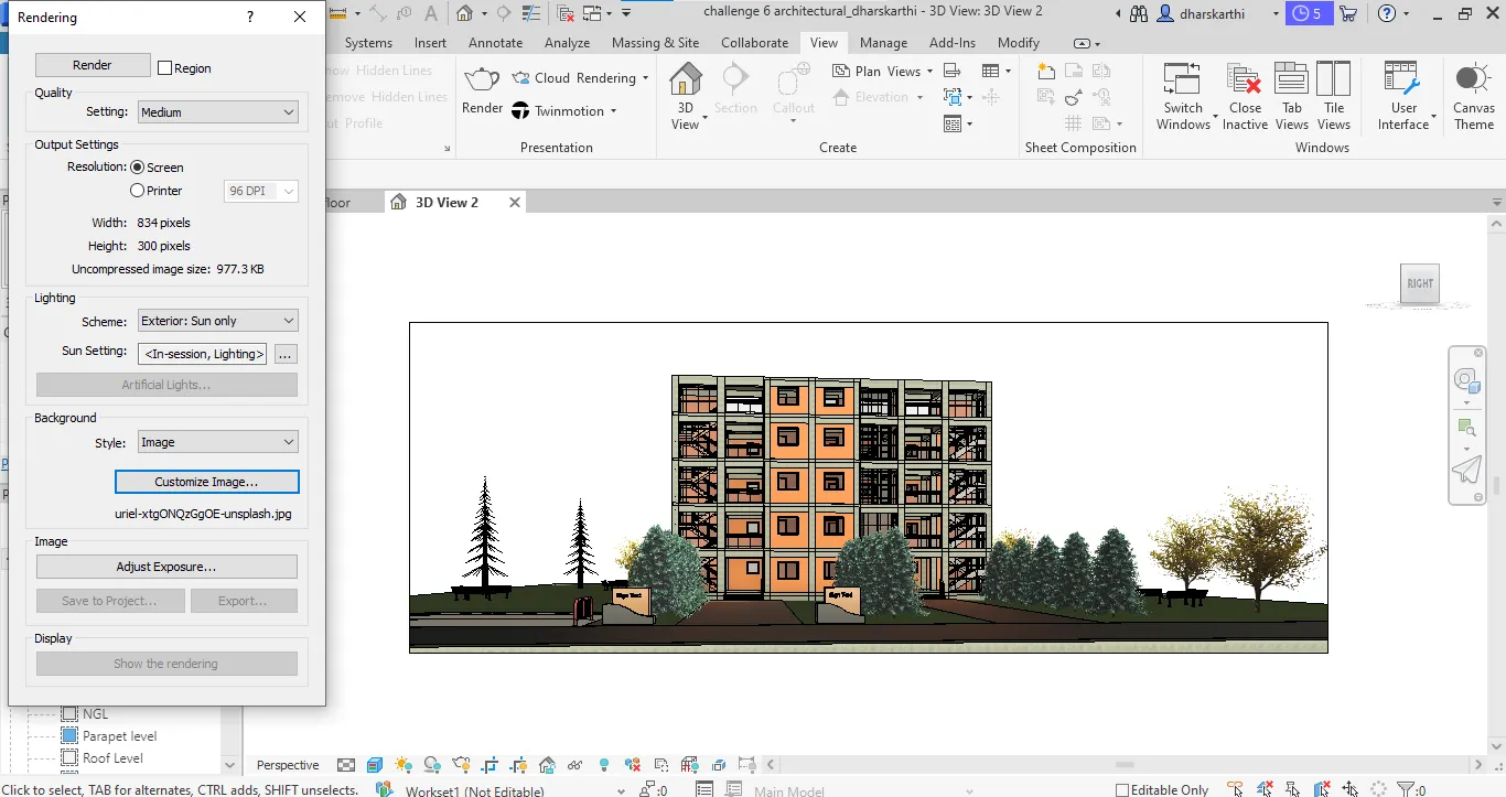
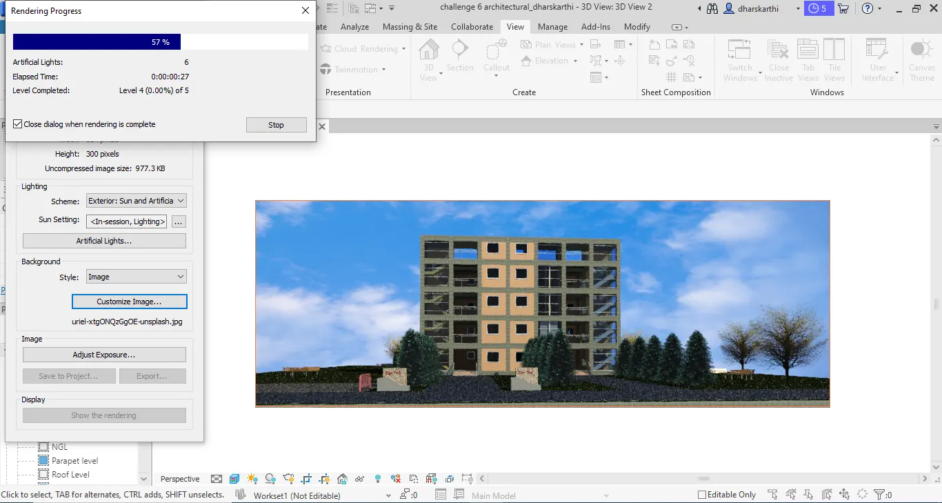
b. Rendering from outside:
- Do the same process on the interior portion rendering. but, place the camera view on exterior face
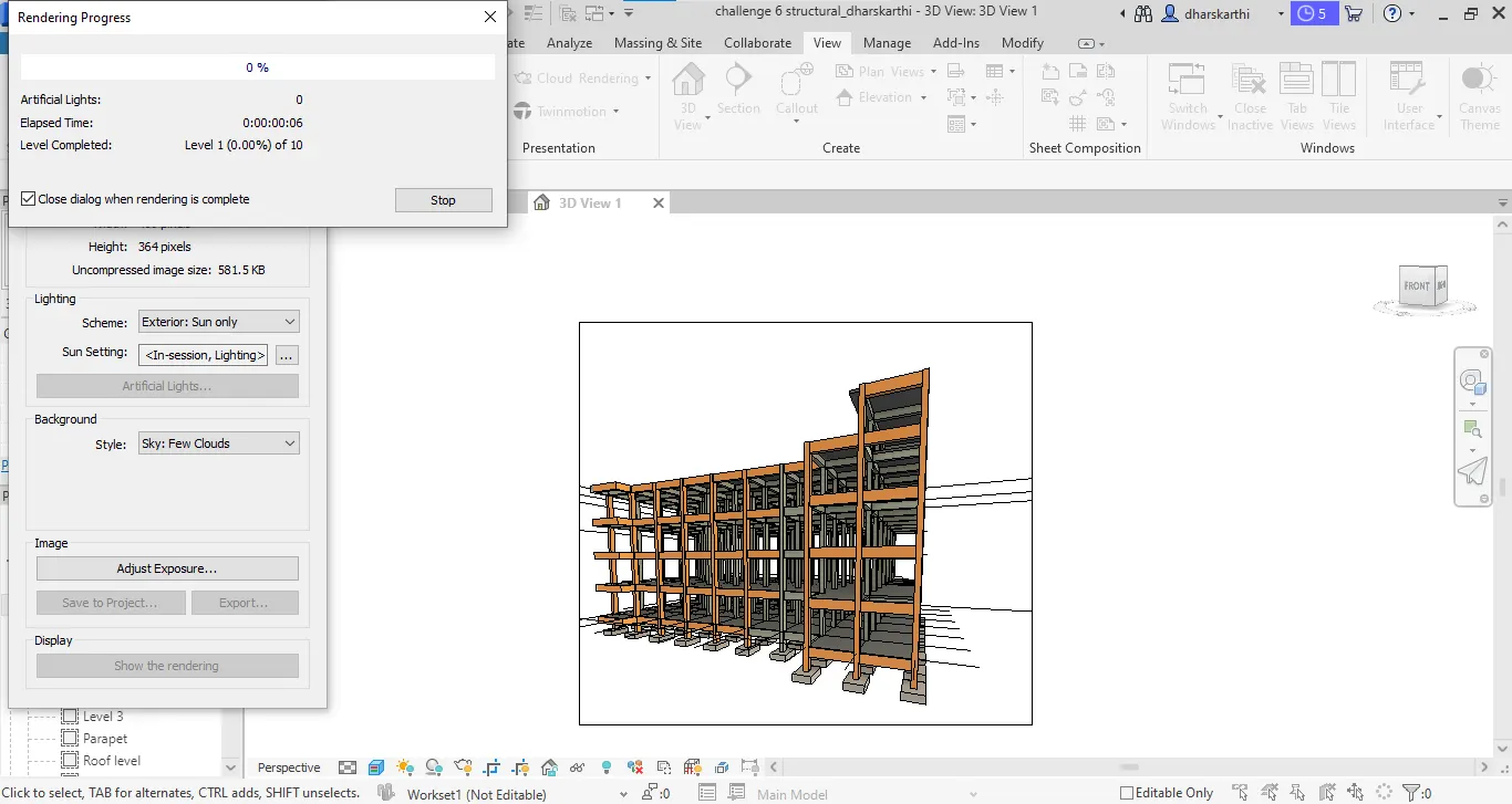
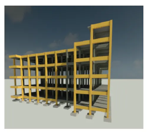
c. Rendering throw stuctural framing:
- Do the same process and do it with the structural files
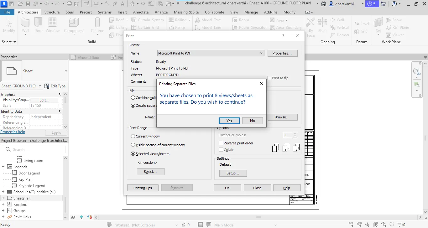
Step - 7:- Print the set of drawing sheets:
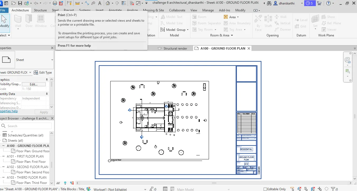
- Goto sheet tab on the project browser then choose any one of drawing file,
- Then we have the option called print on the above the top menu bar or press ctrl+p on keypoard
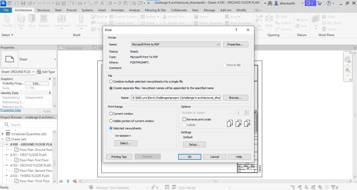
- The print setup will be appeared.
- Then tap the selected views/sheets then select the sheet files then click ok.
- Choose the location then enter the file then the printed file will saved as pdf formate.
Result:-
The creation of Architectural and structural model with 3D rendering using with revit tool was successfuly completed and the resulted files will attached.
THE END