Creating Architectural and Structural model with 3D rendering using REVIT
Challenge 7
<!-- [if !supportLists]-->1) <!--[endif]-->Select the type of structure you want to build from one of the three below:
a. Multi-Unit Residential Apartment
b. Office Buildings
c. School
Aim: To select the type of structure for the below three types to be modelled.
a. Multi-Unit Residential Apartment
b. Office Buildings
c. School
Result:
From the above mention types the structure Multi Unit Residential Apartment is chosen.
<!-- [if !supportLists]-->2) Assume reasonable assumptions for geographic and location details for your project modelling. Based on assumptions and type of structure selected identify the modelling requirements from NBC
Aim: To assume the geographic and location details for the project and select the modelling requirement from NBC.
Procedure:
The building type comes under the residential building and it is situated near the artery road in the Amravati, Maharashtra.
As per NBC 2005 the requirements for the Residential Building are as follows;
<!-- [if !supportLists]-->a. <!--[endif]-->Height limitation:
<!-- [if !supportLists]-->· <!--[endif]--> The road width is 60 feet (18.28 m).
<!-- [if !supportLists]-->· <!--[endif]-->The height of the building is 42 feet (12.8 m) (G+4).
<!-- [if !supportLists]-->· <!--[endif]-->The height of the building should not exceed 1.5 times the width of the road.
<!-- [if !supportLists]-->b. <!--[endif]-->Area limitation:
<!-- [if !supportLists]-->· <!--[endif]-->As per clause 2.3.1 the minimum plot size with ground coverage should not exceed 75%, shall not be less than 40 sqm in small and medium town and not less than 30 sqm. in metropolitan area.
<!-- [if !supportLists]-->· <!--[endif]-->As per the project the plot size is 325 sqm.
<!-- [if !supportLists]-->c. <!--[endif]-->Room limitation:
<!-- [if !supportLists]-->· <!--[endif]-->As per clause C 3.3, the total area of all rooms shall not be less than 15.5 sqm.
<!-- [if !supportLists]-->· <!--[endif]-->Room sizes are standard.
<!-- [if !supportLists]-->· <!--[endif]-->As per project the total area covered is 42’ x 62’6” = 2625 sqft. (244 sqm)
<!-- [if !supportLists]-->· <!--[endif]-->Floor area ratio (FAR) = Total covered area/ Total plot area = 3
<!-- [if !supportLists]-->d. <!--[endif]-->Wall Height:
<!-- [if !supportLists]-->· <!--[endif]-->The height of the wall is 3 m.
<!-- [if !supportLists]-->e. <!--[endif]-->Thickness based on fire and life safety:
<!-- [if !supportLists]-->· <!--[endif]-->The thickness of the external wall is 230 mm and inner wall is 115 mm.
<!-- [if !supportLists]-->3) <!--[endif]-->Using the structural model, include the following components based on the type of structure selected
a. Foundation – Isolated / Wall/Matt Foundation
b. Columns
c. Beams Connected to Columns
d. Roof Framing/ Truss
e. Floor / Decks
f. Floor Openings for Elevators and Stairs
Aim: To include following structural components in the structural model;
a. Foundation – Isolated / Wall/Matt Foundation
b. Columns
c. Beams Connected to Columns
d. Roof Framing/ Truss
e. Floor / Decks
f. Floor Openings for Elevators and Stairs
Procedure:
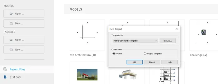
<!-- [if !supportLists]-->· <!--[endif]-->Open Revit software, click on new and select the structural template.
Go to the structural > grid. Then create transvers and longitudinal grid.

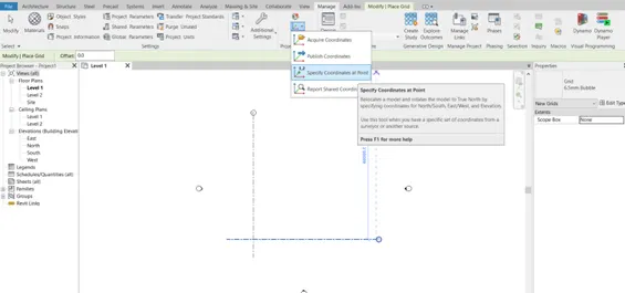
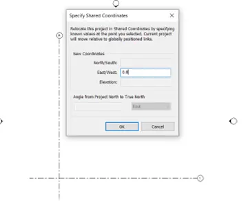
<!-- [if !supportLists]-->· <!--[endif]-->Then go to manage, select project location. In that select coordinates > specify coordinates at point.
<!-- [if !supportLists]-->· <!--[endif]-->Click on horizontal grid enter the new coordinate for North/South As 0’-0”
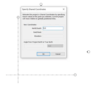
Similarly set the coordinate for the vertical grid
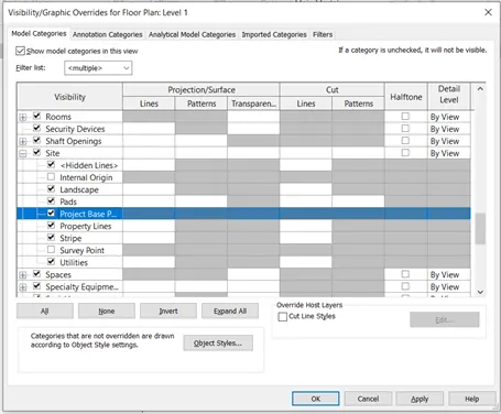
<!-- [if !supportLists]-->· <!--[endif]-->Type VG for visibility graphics
<!-- [if !supportLists]-->· <!--[endif]-->Expand Site and check mark on Project Base Point then click OK
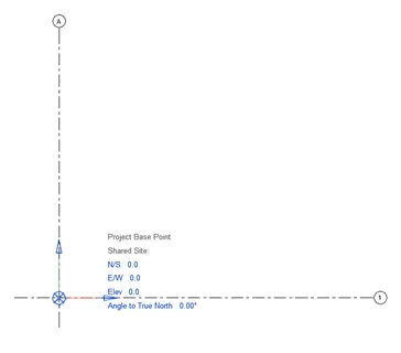
Base point will show in the model sheet
Click on the base point and unpinned
Move the base to the intersection of the girds then pinned the base point
<!-- [if !supportLists]-->· <!--[endif]-->After that save the project as Structural_01
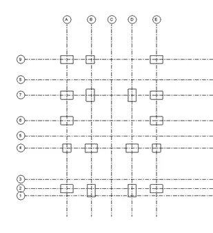
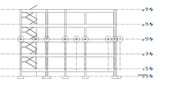
<!-- [if !supportLists]-->· <!--[endif]-->Now create more grids for the project, change the name of the grids as shown in the photo.
<!-- [if !supportLists]-->· <!--[endif]-->Select isolated foundation from the structure tab and select footing sizes as per requirement.
<!-- [if !supportLists]-->· <!--[endif]-->Place the footing as per the design.
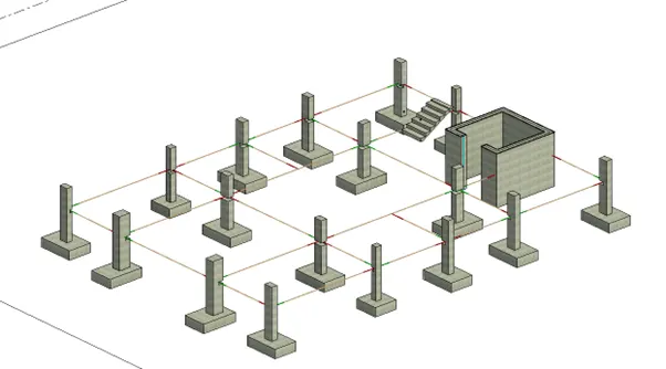
<!-- [if !supportLists]-->· <!--[endif]-->Then select the column from the structure tab, from the drop down menu in the property browser select the desired sizes of the column.
<!-- [if !supportLists]-->· <!--[endif]-->Click on the beam and select the desired sizes of beams and place it on the required positions.
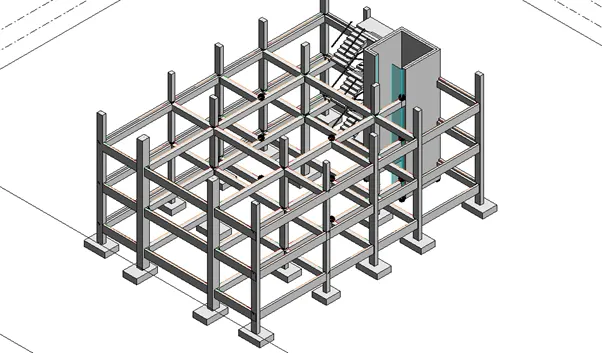
<!-- [if !supportLists]-->· <!--[endif]-->Then select floor and assign on the 1st floor.
<!-- [if !supportLists]-->· <!--[endif]-->Then copy the beams, columns and floor and place on the all the floor.
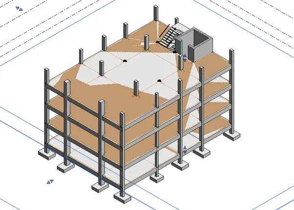
<!-- [if !supportLists]-->· <!--[endif]-->Create slab on the roof level, then select shaft option from the structure tab and create opening at the location of staircase and elevator.
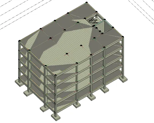
Result
The aim of the question is successfully achieved.
<!-- [if !supportLists]-->4) <!--[endif]-->Using the architectural model, include the following components based on the type of structure selected
<!-- [if !supportLists]-->a. <!--[endif]-->Wall Layout with appropriate material and finishing
<!-- [if !supportLists]-->b. <!--[endif]-->Exterior façade with fancy finish
<!-- [if !supportLists]-->c. <!--[endif]-->Interior partition walls to size rooms
<!-- [if !supportLists]-->d. <!--[endif]-->Components to add details to a room (Desk, Chair, Lighting, Plumbing fixtures)
<!-- [if !supportLists]-->e. <!--[endif]-->Add components such as stairs Elevators
<!-- [if !supportLists]-->f. <!--[endif]-->Have at-least one side of the building with curtain walls and glass panels
<!-- [if !supportLists]-->g. <!--[endif]-->Include interior and exterior lighting fixtures
<!-- [if !supportLists]-->h. <!--[endif]-->Place proper topographic components from outside (Trees, Parking, Plants) to add details to the model
Aim: To include following components based on the structure selected;
a. Wall Layout with appropriate material and finishing
b. Exterior façade with fancy finish
c. Interior partition walls to size rooms
d. Components to add details to a room (Desk, Chair, Lighting, Plumbing fixtures)
e. Add components such as stairs Elevators
f. Have at-least one side of the building with curtain walls and glass panels
g. Include interior and exterior lighting fixtures
h. Place proper topographic components from outside (Trees, Parking, Plants) to add details to the model
Procedure
<!-- [if !supportLists]-->· <!--[endif]-->Open architectural template and save it as Residenstial_Architectural_01.
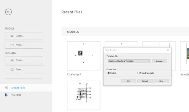
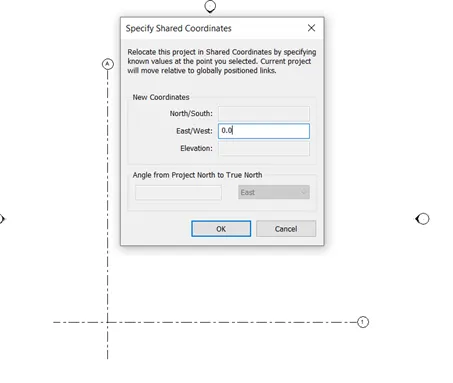
<!-- [if !supportLists]-->· <!--[endif]-->Then draw the grid lines ans specify the coordinates from the manage > project location > specify coordinates at point.
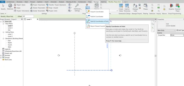
<!-- [if !supportLists]-->· <!--[endif]-->Click on horizontal grid enter the new coordinate for North/South as (0,0)
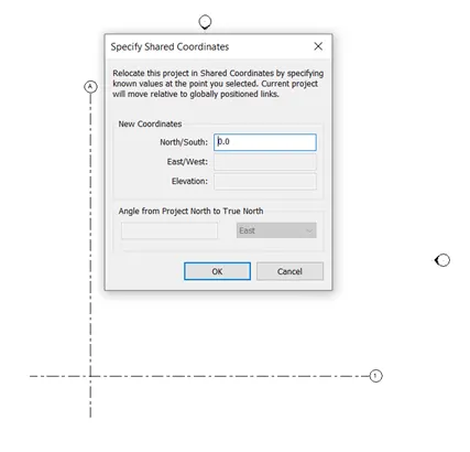
<!-- [if !supportLists]-->· <!--[endif]-->Similarly set the coordinate for the vertical grid East/West to (0,0)
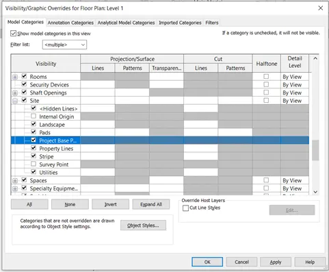
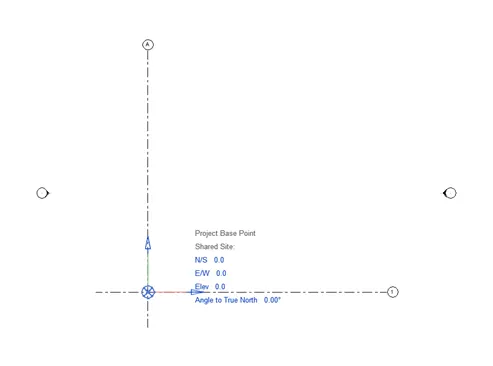
<!-- [if !supportLists]-->· <!--[endif]-->Then press VG and toggle project base point under the site option.
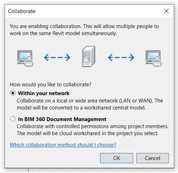
<!-- [if !supportLists]-->· <!--[endif]-->Then click on the collaborate tab and select within your network and click ok, and save the project.
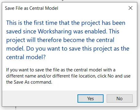
<!-- [if !supportLists]-->· <!--[endif]-->Then link the project with the structure file which is created in the earlier question.
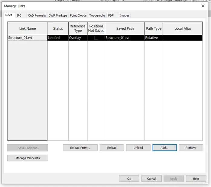
<!-- [if !supportLists]-->· <!--[endif]-->Select the coordinates and set the link to the current coordinates.
<!-- [if !supportLists]-->· <!--[endif]-->Now create the grips and level referring to the previous linked structural template.
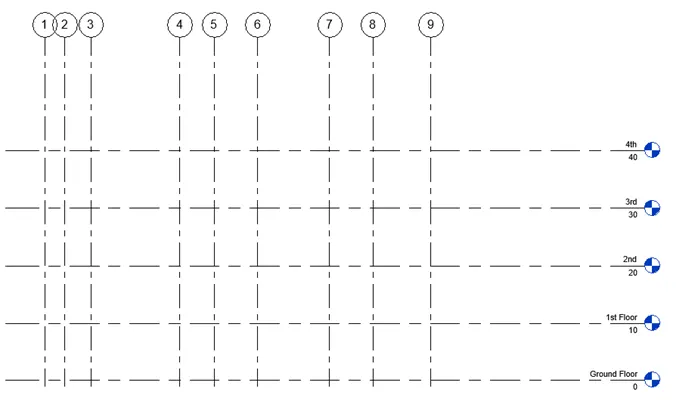
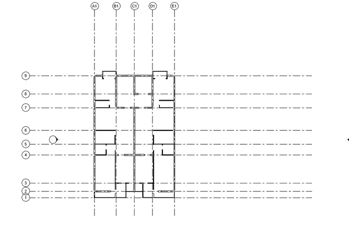
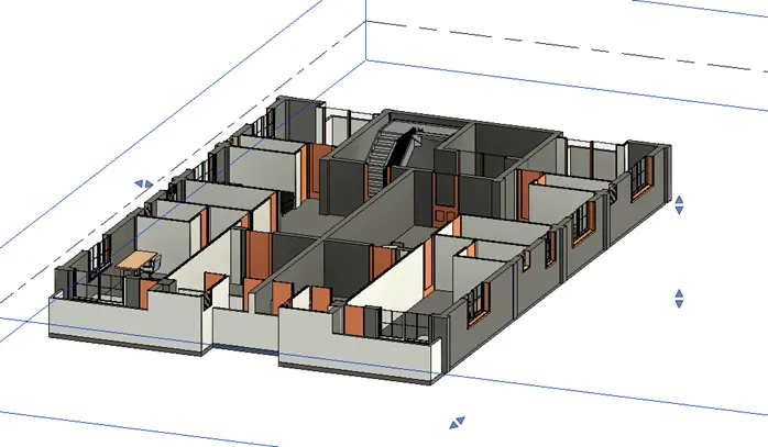
<!-- [if !supportLists]-->· <!--[endif]-->Now go to the component tab under the architectural tab and place doors, windows, furniture and other required components in the model.
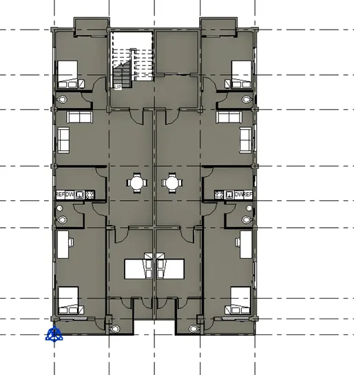
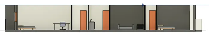
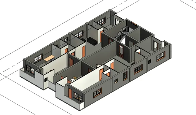
Result:
The aim of the question is achieved. All the goals mention in the aim is achieved.
<!-- [if !supportLists]-->5) <!--[endif]-->Provide a set of drawings in an architectural and structural model to list the following details with categories and appropriate sheet templates included
<!-- [if !supportLists]-->a. <!--[endif]-->Floor Plans with Annotations
<!-- [if !supportLists]-->b. <!--[endif]-->Elevations
<!-- [if !supportLists]-->c. <!--[endif]-->Sections
Aim: Provide a set of drawings in an architectural and structural model to list the following details with categories and appropriate sheet templates included
a. Floor Plans with Annotations
b. Elevations
c. Sections
Procedure:
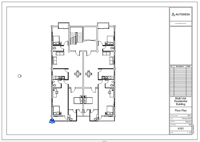
<!-- [if !supportLists]-->a. <!--[endif]-->Floor plans with annotations
Open architectural model then go to the view tab. Click on the sheet button then select the desired size of the sheet and click ok.
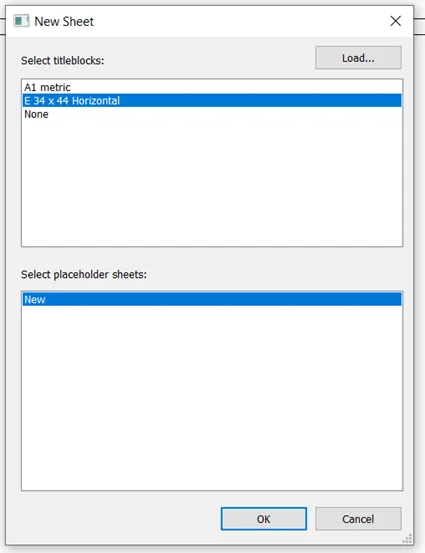
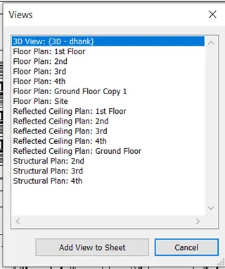
Rename the sheet as floor plan and provide all the necessary details. Then select the ground floor and place in the sheet
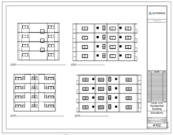
<!-- [if !supportLists]-->b. <!--[endif]-->Elevation
Click on View tab then select plan and then select
<!-- [if !supportLists]-->c. <!--[endif]-->Sections
Click on the view tab select section option the place the section on the model as required.

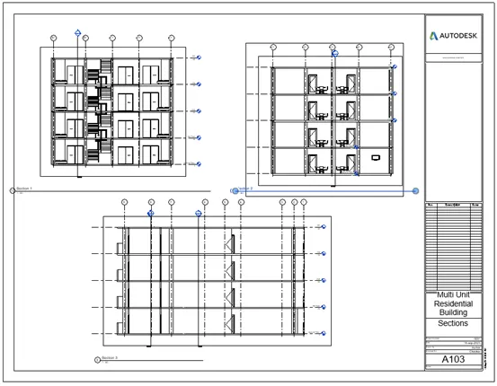
Result: The aim of the question is achieved.
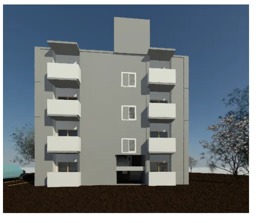
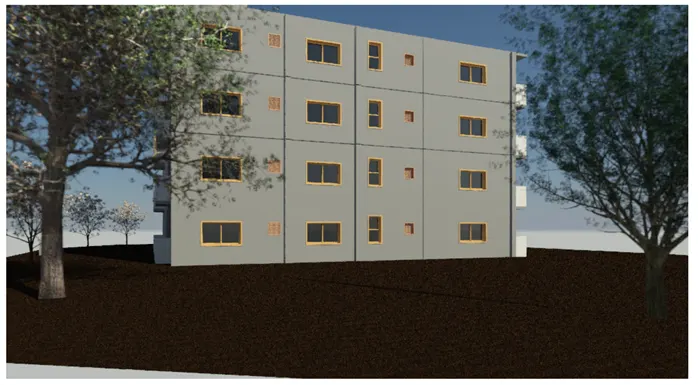
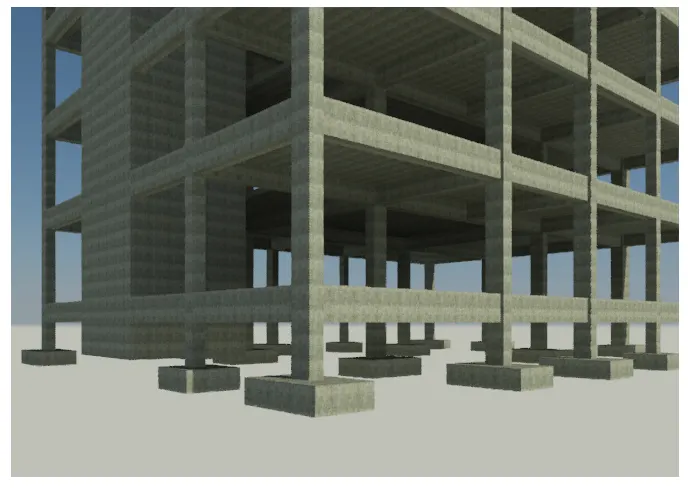
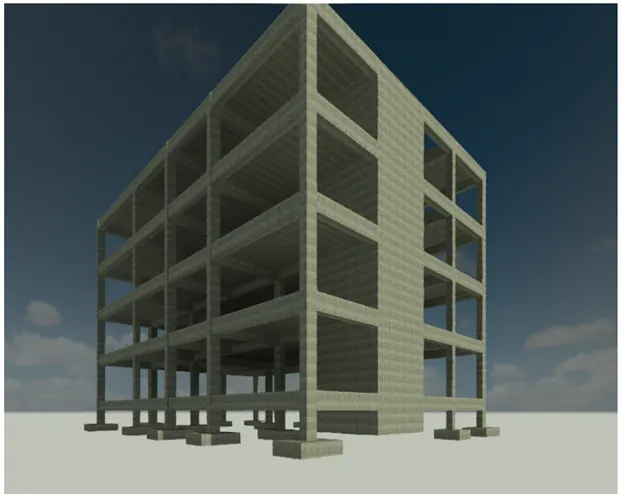
<!-- [if !supportLists]-->6) <!--[endif]-->Using the Rendering settings, Render images of the 3D model produced and include the rendered images to the drawing sheets
<!-- [if !supportLists]-->a. <!--[endif]-->Rendering from interior rooms
<!-- [if !supportLists]-->b. <!--[endif]-->Rendering from out showing topographic features
<!-- [if !supportLists]-->c. <!--[endif]-->Rendering through structural framing
Aim: To produce 3D images of the model using the Rendering settings, and include the rendered images to the drawing sheets
Procedure:
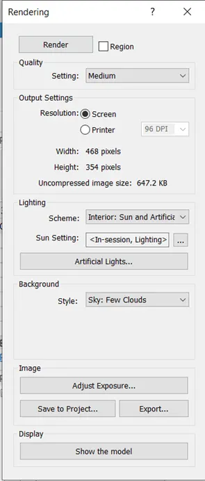
Click in the view tab select camera under3D drop down. Set the camera as required then click on the render tab, dialog box will appear then adjust as per requirement.
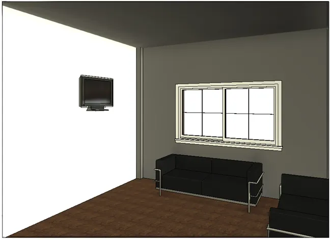
<!-- [if !supportLists]-->a. <!--[endif]-->Rendering from interior rooms
Living Room
Bed Room
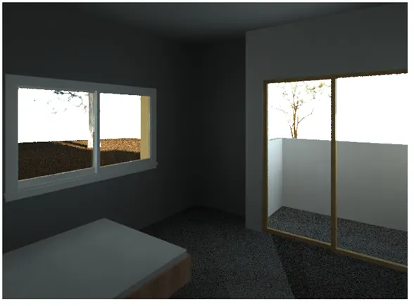
Dining Hall
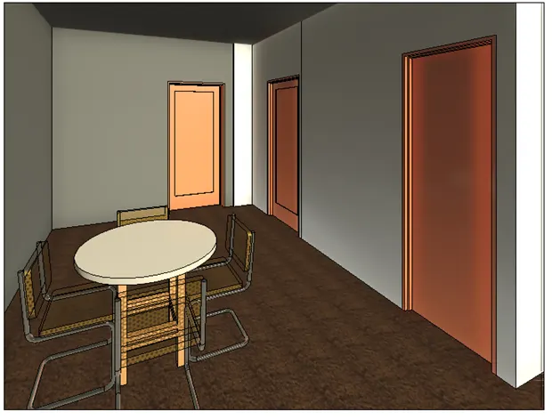
Kitchen
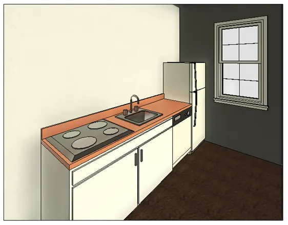
Master Bedroom
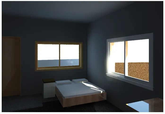
<!-- [if !supportLists]-->b. <!--[endif]-->Rendering from out showing topographic features
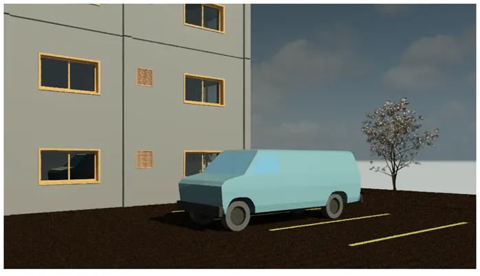
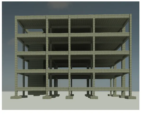
<!-- [if !supportLists]-->c. <!--[endif]-->Rendering through structural framing
<!-- [if !supportLists]-->7) <!--[endif]-->Print the set of drawing sheets created and submit the drawings from the architecture and structure model
Aim: To print the set of drawing sheets created and submit the drawing from the architecture and structure model.
Procedure:
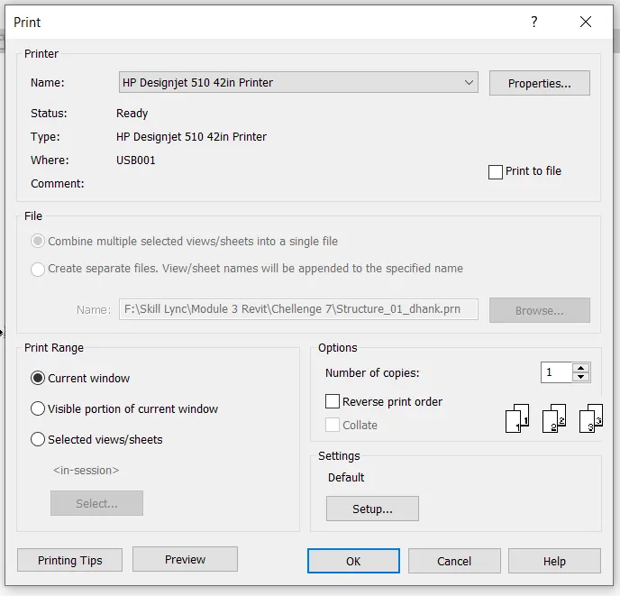
Click on the file menu print option is there or press Ctrl+P print dialog box will appear.