Creating Architectural and Structural model with 3D rendering using REVIT
1) Select the type of structure you want to build from one of the three below
a. Multi Unit Residential Apartment
b. Office Buildings
c. School
Ans:- As per the given options in the question I am opting for Multi Unit Residential Apartment
2)
Ans:- For Geographic and location details assumptions which I have made are:-
1. My project is in residential area (medium populated)
2. Road width in front of my apartment is 60 feet
3. My project is in plain area (geographical)
As per the NBC
Height Limit as per FAR Calculation and as per NBC Table 5 V-1
Min length and width of rooms as per NBC V-1
Fire and safety from NBC part IV
3)
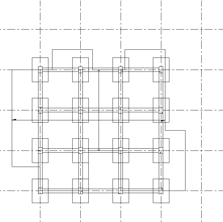
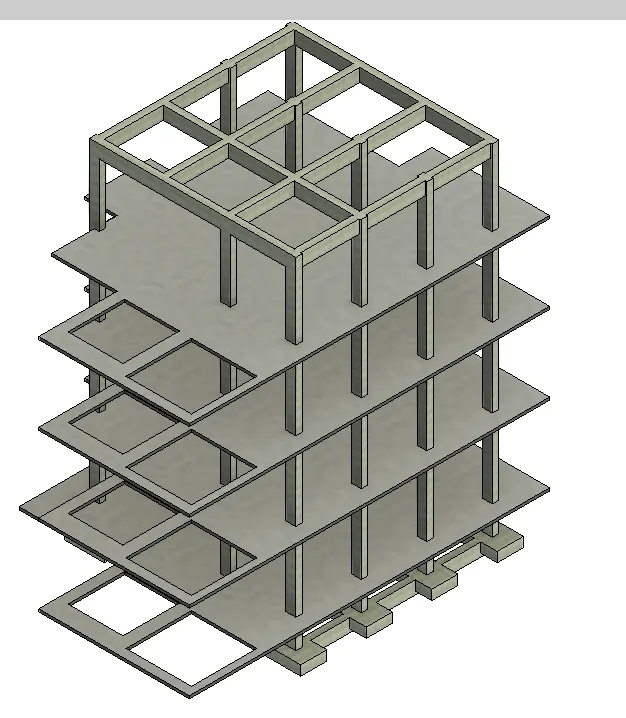
AIM:- Make a project using structural model and include the following components
Commands used:-
Grids
Levels
Columns
Isolated foundation
Beams
Floor structural
Shaft for lift and staircase
Procedure:-
Open a new file in structural template and save it with a appropiate name
Select collaborate and do the collaboration and make it as a central file
Select Structural and select grids and daw grid in horizontal and vertical
Select the manage tab and select coordinate and select specify coordinate
Specify the coordinate as 0'0" in both the grids and pin it
save it
Open a new template as architectural template and save it with a appropiate name
Select collaborate and do the collaboration and make it as a central file
Select Architectural and select grids and daw grid in horizontal and vertical
Select the manage tab and select coordinate and select specify coordinate
Specify the coordinate as 0'0" in both the grids and pin it
save it
Select the manage link and link the structural template in the architectural
Both the grids will appear
Select the manage tab and accquire the coordinate of the linked grid
select the relocate project and select the gridand overlap them now its good to go
save it
Open the structural template
draw the gids at equal interval in both x axis and y axis
select the elevation plan and draw the levels as 12' from one floor to another
select the floor plan and draw the floor plan as per the drawing or your building structure and copy it till roof
Select the columns at grids and draw columns In properties tab select the column propeerty and size
Select the footing and draw footings at the columns
Select the beam and draw beams connected to the columns and select the contraint to First floor from ground floor as beams are at top of the floors
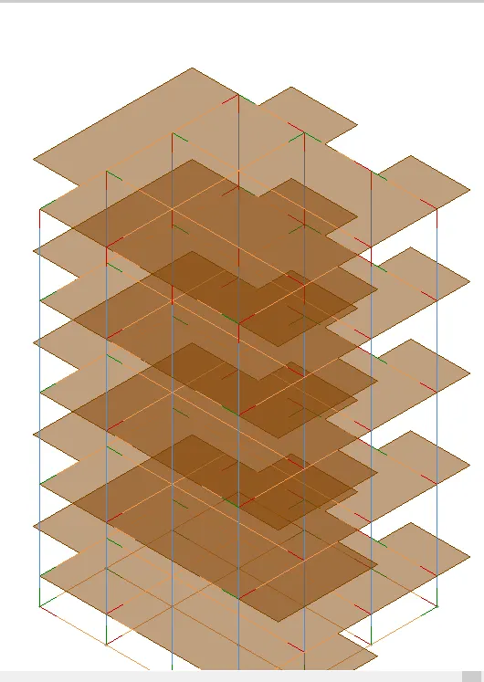
After making beams and columns red line will show that is analytical which can be off by pressing vg and select custom and select annotation and off the anlytical
select the shaft for lift opening and staircase opening
My structure framing plan is ready
Results:-In result I have shown analytical part of the building too as its in structural template revit creates it automatically
4) AIM:- Using architectural template create the walls , facade and other components of the building and give a complete building look with all the components
Commands Used:-
walls
material
Partition wall
Components as desk, chair lights etc
Stair
ceiling
roof
windows
doors
Railing
Procedure:-
Open the architectural template and we will see all the grids in the template which we made it in structural template
Select the copy monitor tool and select copy and select the grids
go to the vg setting and select custom in annotation off the grids
Now we will see the grids of architectural only
Select the elevation and do the same as of grids to levels
Select and pin it
Select the exterior wall and draw the walls in the ground floor
Go to the 3d view and select top constraint to roof
Select the wall near the staircase area(lobby) and in property tab select glazed wall
Select the GF plan and select partition wall and draw the roomss, kithen, toilets, etc
select the door and draw the doors whereever required
selct the window and draw the windows where ever required in property tab we can select type of windows
Select all the doors and windows and select copy and paste it to selected level till roof
All the doors and windows are made
select the ceiling and draw ceiling in the ground floor by selecting walls click the tick button
copy all the ceiling and paste it to selected level
select the wall properties and select type of wall to be used
Select the FF plan and select railing and draw railing in the balconies
Select the insert command and select the family and select the components as beds, tables, lights, plumbing fixtures etc
Select the add the component and select the component and add it to its appropiate place
Select the roof and select roof by walls and draw the roof
Select the component of trees and place it at the exterior portion of the building
Result:-
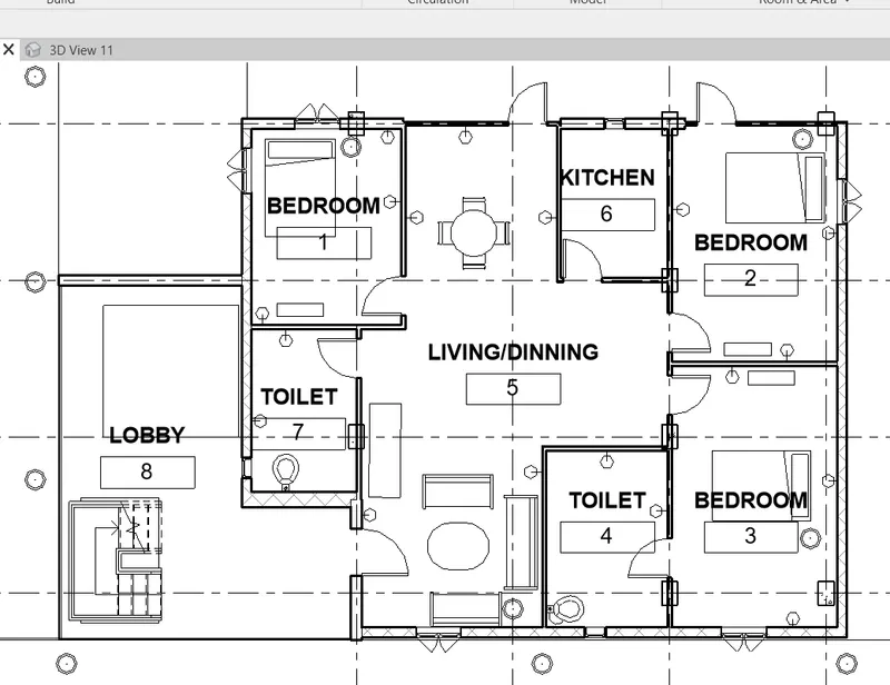
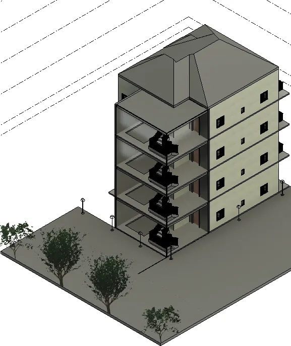
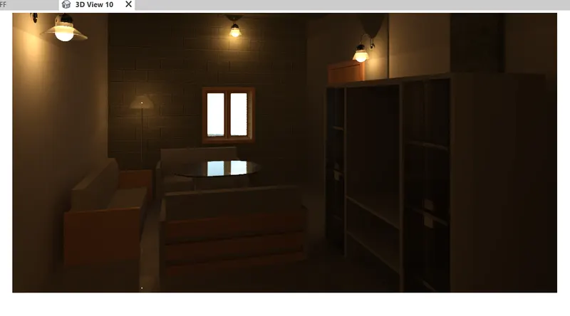
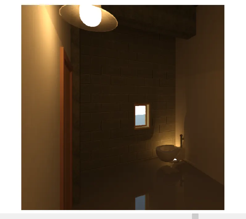
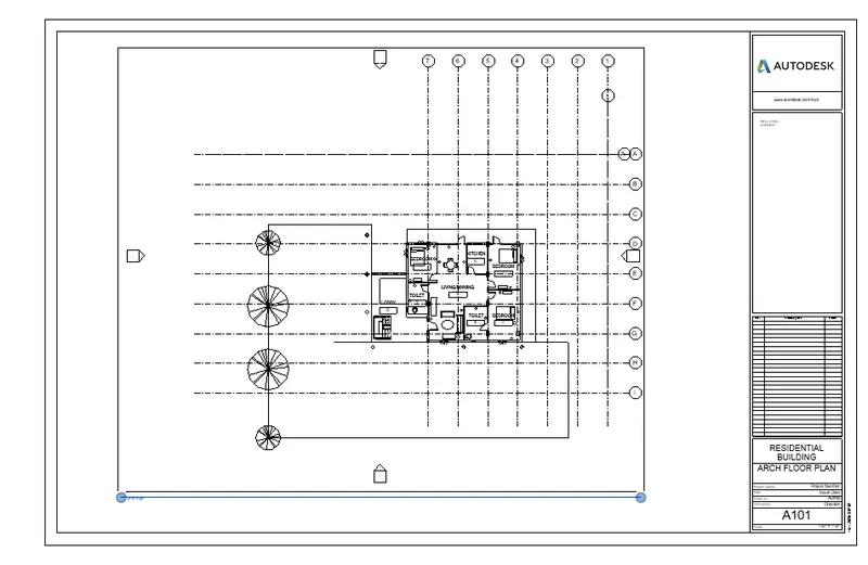
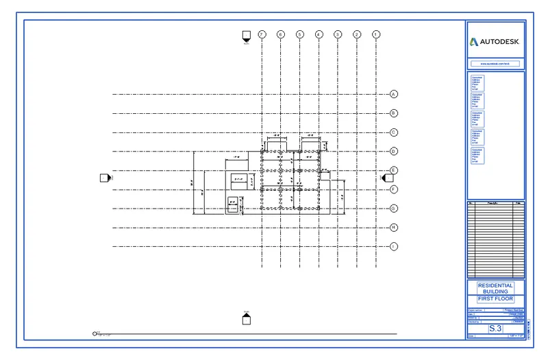
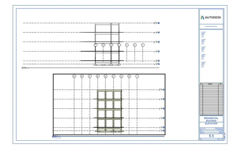
5) AIM:- USe proper sheet templates for the set of drawings
Commands used:-
Sheets
Edit sheets
Procedure:-
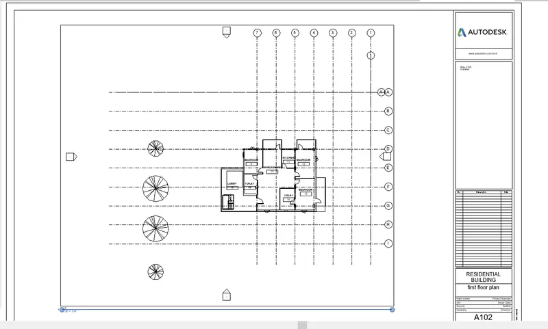
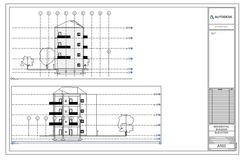
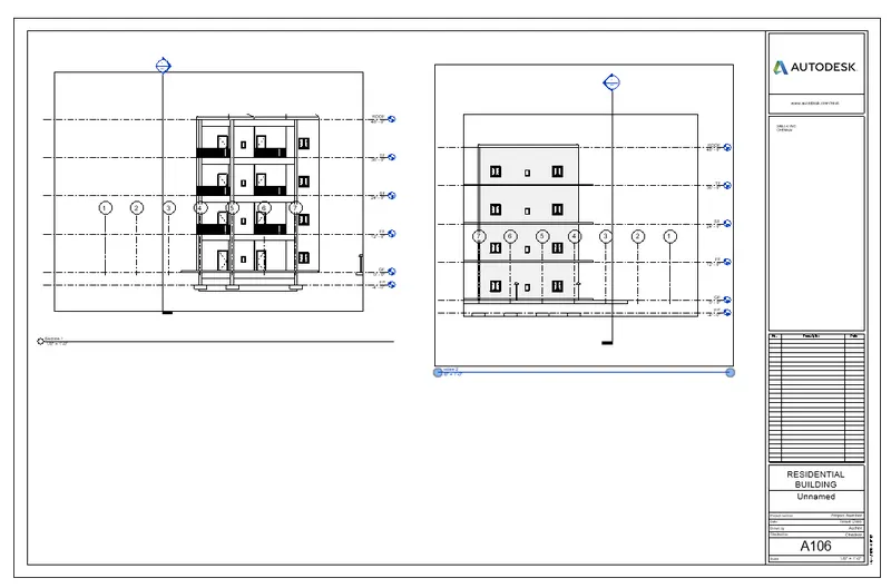
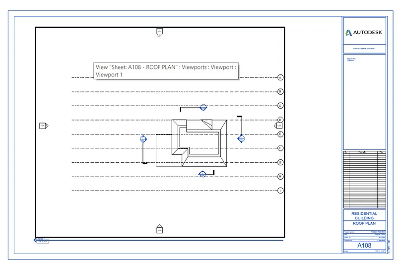
Select the view tab and select sheet and load it from the family
Double click and edit the sheet and load it in the project
Drag the plans , elevations, section in the sheet and rename the sheet and drawing number and name as per the requirment and save it
Results:-
6) Aim:- Render the 3D images
Commands used:-
Render
Procedure
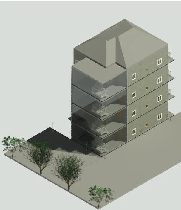
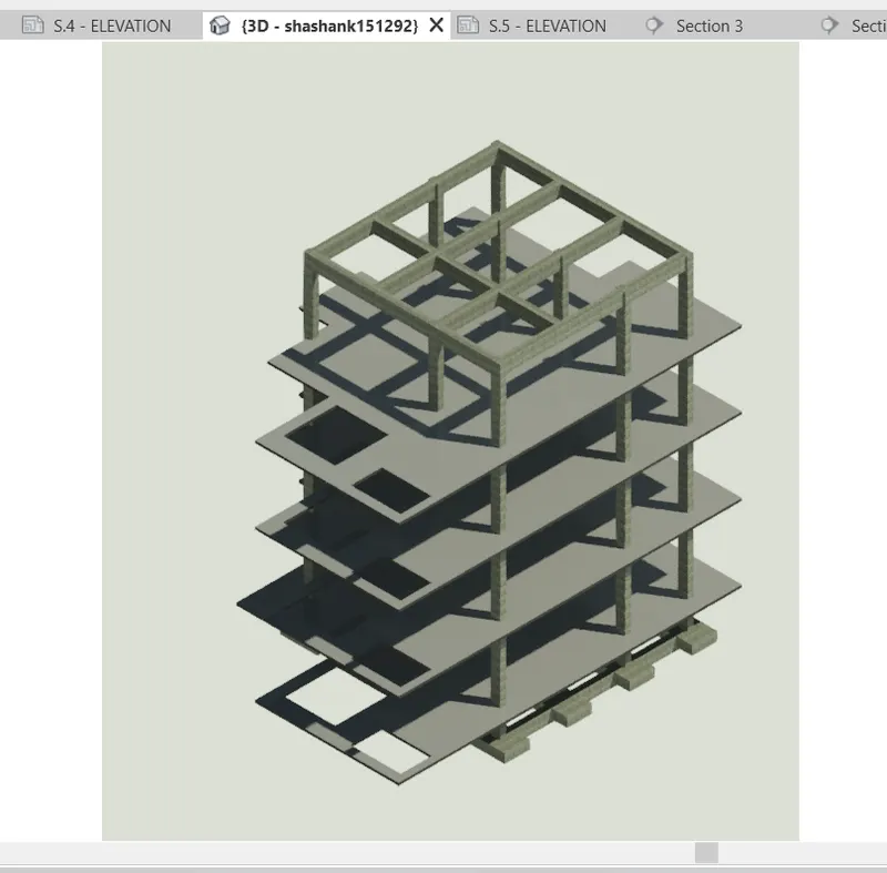
Select the 3D images og the interior rooms, exterior and structural framing and select the render and do the rendering
Select the properties like exterior sun and artificial setting, or artificial setting, clouds etc
Results:-
7)
Aim:- Print the sets of drawing sheets and submit for execution at site
Commands Used:-
Setup page
Select the plotter
Procedure:-
Select the views and click print option
Adjust the setting of the page and print the drawing sheets