Creating Architectural and Structural model with 3D rendering using REVIT
1) Select the type of structure you want to build from one of the three below:
a. Multi-Unit Residential Apartment
b. Office Buildings
c. School
Over here I decide to choose Multi-Unit Residential Apartment.
2) Assume reasonable assumptions for geographic and location details for your project modeling. Based on assumptions and type of structure selected identify the modeling requirements from NBC
AIM:- To assume reasonable assumptions for geographic and location details for your project modeling based on requirements from NBC
INTRODUCTION:-
- Building Site is plain area.
- Project situated in urban area.
- Height of the project is 12m
- Front open space= 3m, for plot facing street width=7.5m (From NBC part 3, Cl. 8.2.1.1)
- Rear open space =3m (for residential building, Cl. 8.2.1.2)
- Minimum Side open space=3m (Cl. 8.2.1.3)
3) Using the structural model, include the following components based on the type of structure selected
a. Foundation – Isolated / Wall/Matt Foundation
b. Columns
c. Beams Connected to Columns
d. Roof Framing/ Truss
e. Floor / Decks
f. Floor Openings for Elevators and Stairs
AIM:- To include the following components based on the type of structure Using the structural model selected
a. Foundation – Isolated / Wall/Matt Foundation
b. Columns
c. Beams Connected to Columns
d. Roof Framing/ Truss
e. Floor / Decks
f. Floor Openings for Elevators and Stairs
INTRODUCTION:- Revit helps the Structural engineer to analysis the structural element of the building. Structure tab consist of Structure( like Beam, Column, etc), connections, foundations, reinforcement, etc.
PROCEDURE:-
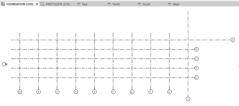
- Open Structural model that previously created in week 6.
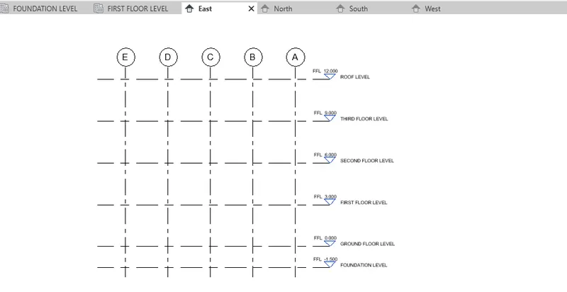
- Create levels in the elevation.
Foundation – Isolated / Wall/Matt Foundation
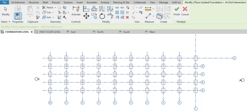
- Select isolated foundation from the structure tab to create footing in the foundation level.

- Place isolated foundation at the grid intersections. Click finish.
Columns
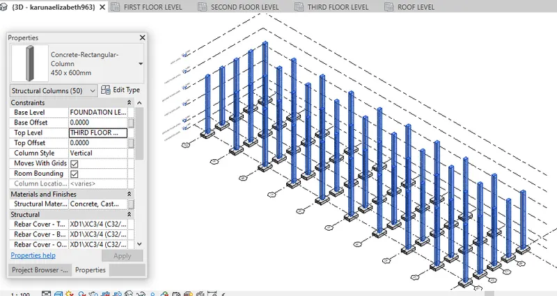
- Select Column from the structure tab to create column above the foundation.

- Select vertical structural column at the grid line intersection.

- Provide concrete column of 450mm x600mm from foundation level to third floor level.
- Check in 3D view.
Beams Connected to Columns
- Select Beam from the structure tab to create beams from ground to roof floor.

- Select concrete rectangular beam of 300 x 600mm and place the beam on the grid line.
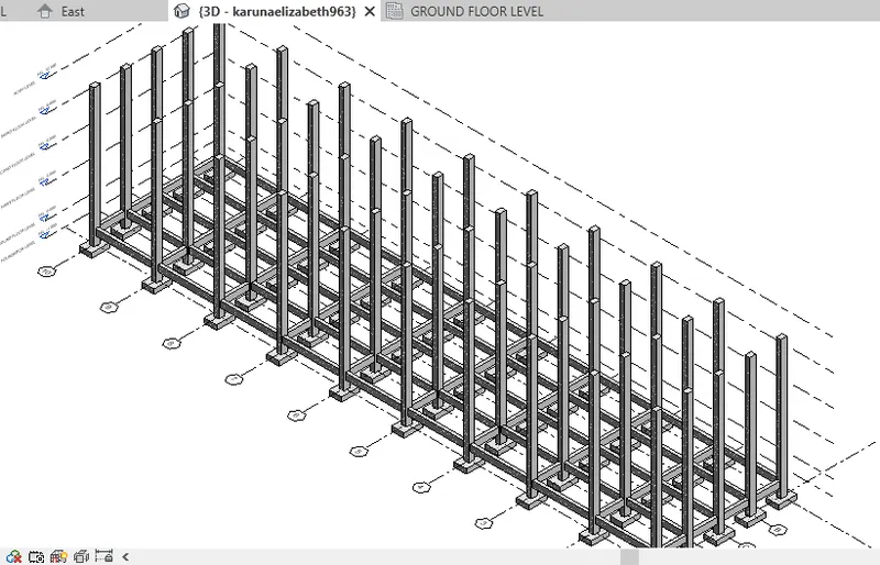 Concrete beam in the ground floor
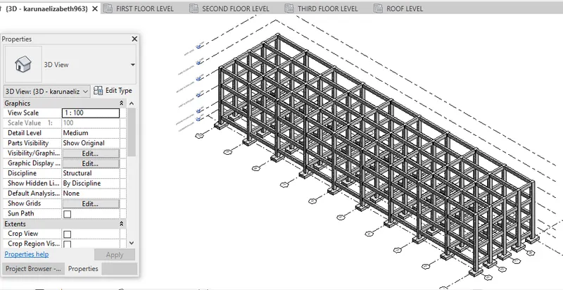
- Similarly, Place concrete beam in the first floor and above.
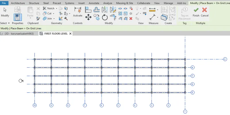
- Check in 3D view after placing the beam.
Floor / Decks
- Select Structural floor from the structure tab to create floors.

- Create floor boundary from ground floor till roof floor level.
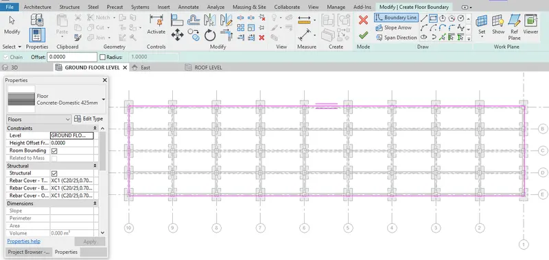
- Hence, created Structural floor in ground floor level.
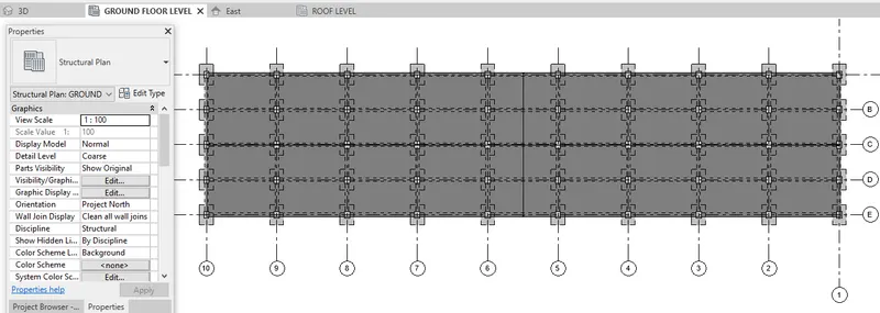
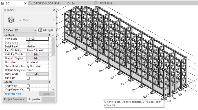
- Similarly, create Structural floor from first floor to third floor level.
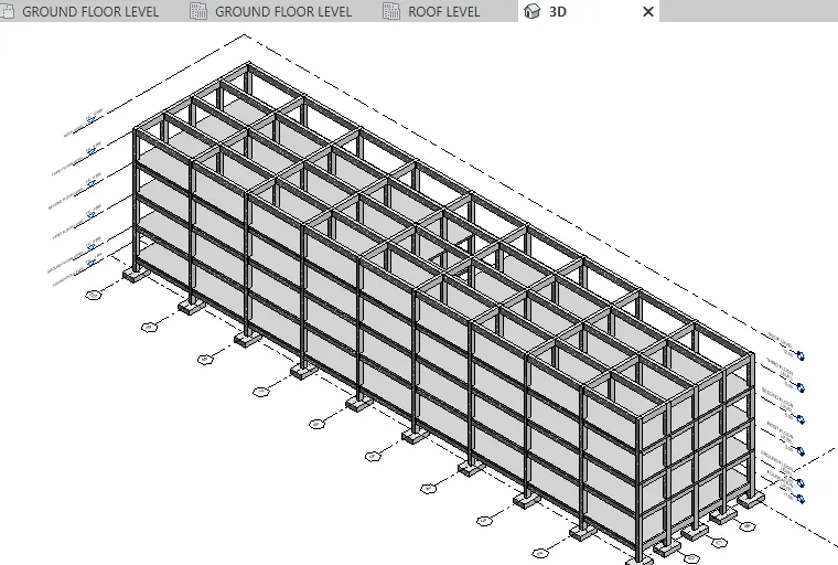
Floor Openings for Elevators and Stairs
- Select Shafts openings from the structure tab to create floor openings for elevators and stairs.

- Create shaft openings from first floor level to third level for staircase.
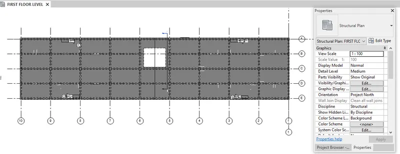
- Check shaft opening in 3D view.
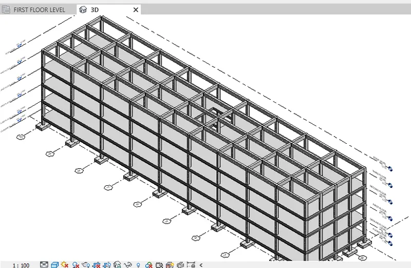
RESULT:- Hence, included the various components like Isolated foundation, Columns, Beams, Floor and Floor Openings for Stairs based on the type of structure Using the structural model selected.
4) Using the architectural model, include the following components based on the type of structure selected
a. Wall Layout with appropriate material and finishing
b. Exterior façade with fancy finish
c. Interior partition walls to size rooms
d. Components to add details to a room ( Desk, Chair, Lighting, Plumbing fixtures)
e. Add components such as stairs Elevators
f. Have at-least one side of the building with curtain walls and glass panels
g. Include interior and exterior lighting fixtures
h. Place proper topographic components from outside ( Trees, Parking, Plants) to add details to the model
AIM:- To include the following components based on the type of structure selected using the architectural model
a. Wall Layout with appropriate material and finishing
b. Exterior façade with fancy finish
c. Interior partition walls to size rooms
d. Components to add details to a room ( Desk, Chair, Lighting, Plumbing fixtures)
e. Add components such as stairs Elevators
f. Have at-least one side of the building with curtain walls and glass panels
g. Include interior and exterior lighting fixtures
h. Place proper topographic components from outside ( Trees, Parking, Plants) to add details to the model
INTRODUCTION:- Architectural tab consists of walls, stairs, railings, doors, windows, roof, ceilings, etc which gives aesthetic appearance to the model created. Various components can be placed to the required room position.
PROCEDURE:-
- Close the previously created structural model and sychronize with the central.
- Open the architectural model previously created in week 6 with linked structural model.
- Go to floor plan level 0, select the model.
- Under Collaborate tab, select link to copy/monitor.

- Select the link to copy, Then select all the grid lines.
- Click finish.
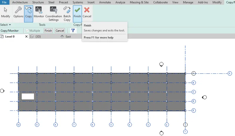
- Go to visibility graphics, under Revit links, select by Host view.
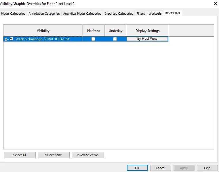
- Under annotation category, untick grids so that linked grid lines are not visible.
- Similarly, untick levels from visibility graphics.
- Select floor plan from the plan views under view tab.

- Select all the levels to create new levels in the project window.
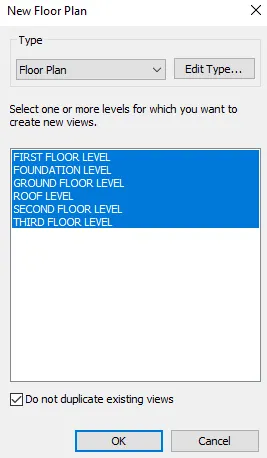
Wall Layout with appropriate material and finishing
- Under Architectural tab, select wall.
- Set wall with appropriate material and finishing in proerty window.

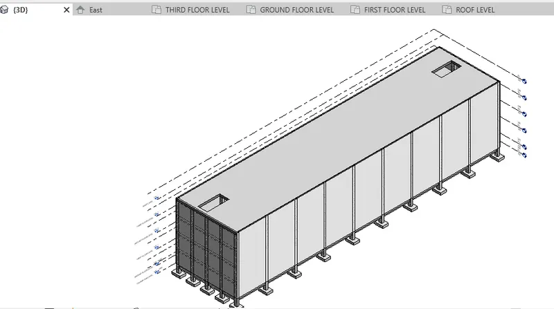
- Provide exterior wall to all the floors.
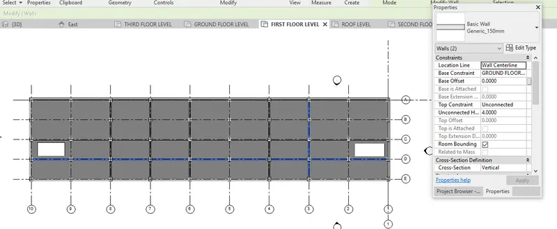
Interior partition walls to size rooms
- Provide interior walls from ground floor till third floor of 150mm thickness.
Components to add details to a room ( Desk, Chair, Lighting, Plumbing fixtures)
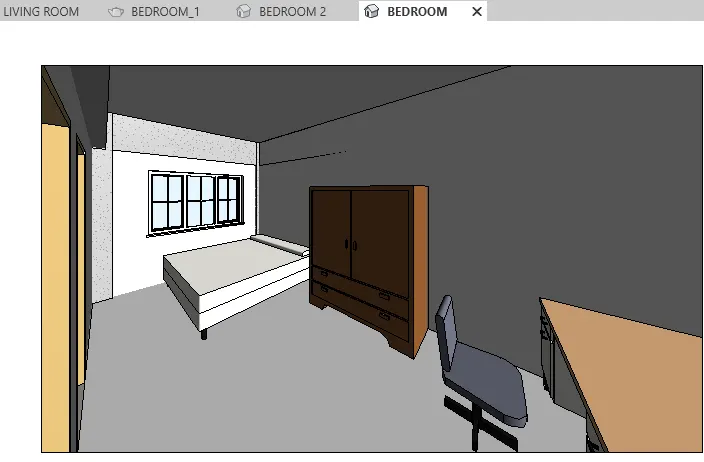
- From view tab, select camera to view the interior components such as Desk, Chair, Lighting, Plumbing fixtures.

- Place the camera in the required position of any rooms.
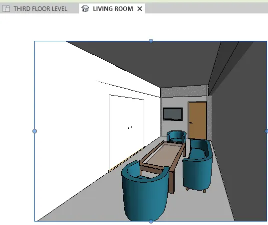 3D CAMERA VIEW OF LIVING ROOM
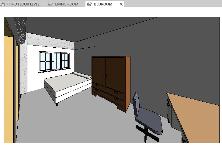 3D CAMERA VIEW OF BEDROOM
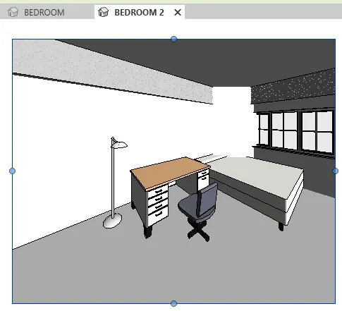 3D CAMERA VIEW OF BEDROOM WITH LIGHTING FIXTURES
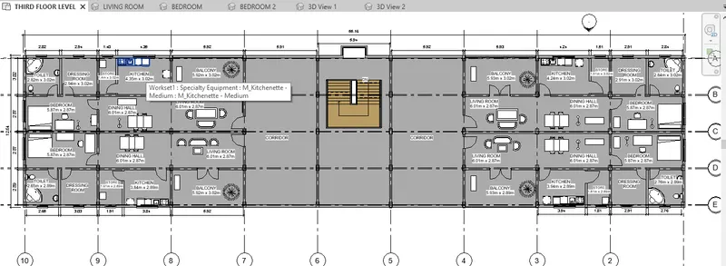
Add components- stairs
- Under Architectural tab, select stair


- Provide staircase for easy access with appropiate width.
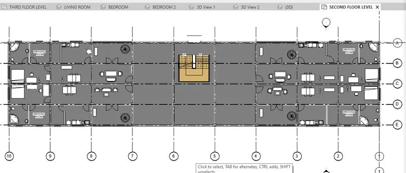
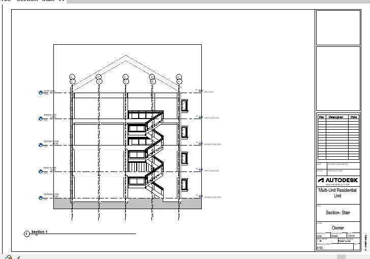
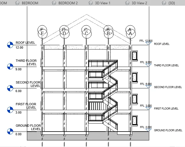 SECTION VIEW OF STAIRCASE
Place proper topographic components from outside
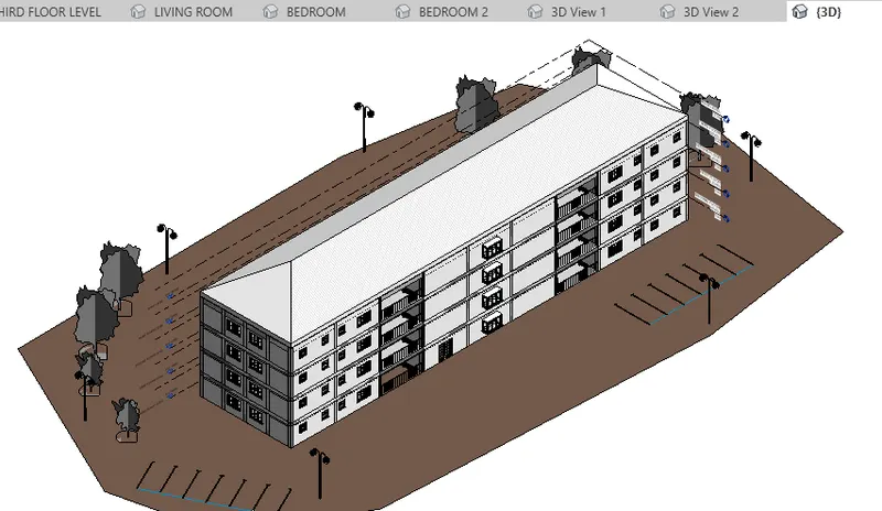
RESULT:- Hence, included the architectural components based on the type of structure selected using the architectural model
5) Provide a set of drawings in an architectural and structural model to list the following details with categories and appropriate sheet templates included
a. Floor Plans with Annotations
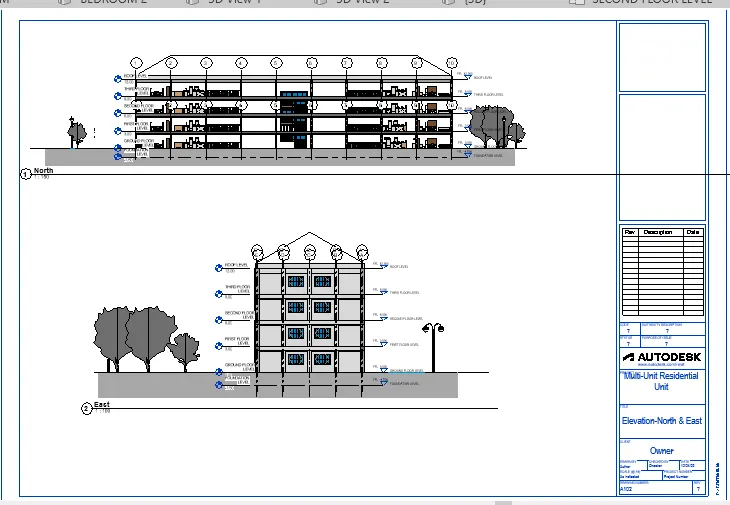
b. Elevations
c. Sections
AIM:- To provide a set of drawings in an architectural and structural model to list the following details with categories and appropriate sheet templates included
a. Floor Plans with Annotations
b. Elevations
c. Sections
INTRODUCTION:- Under View tab, select sheet to place architectural and structural drawings of the model.
PROCEDURE:-
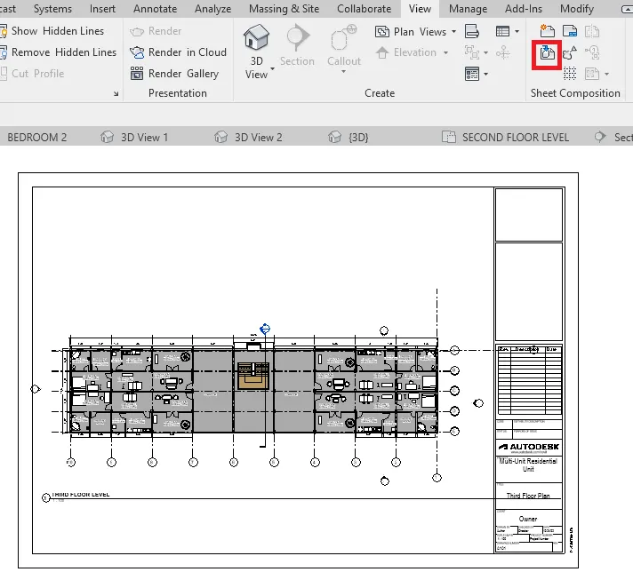
Floor Plans with Annotations
- Under View tab, select sheet which includes architectural and structural drawing.

- Place floor plan view in the A1 sheet.
Elevations
- Similarly, Place elevation view in the A1 sheet.
Sections
- Similarly, Place staircase section view in the A1 sheet.
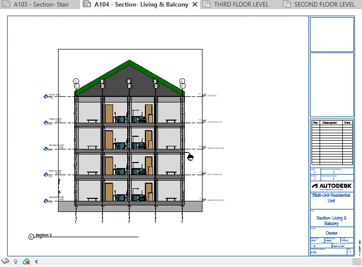
RESULT:- Hence, provided a set of drawings in an architectural and structural model in appropriate sheet templates including Floor Plans with Annotations, Elevations and Sections
6) Using the Rendering settings, Render images of the 3D model produced and include the rendered images to the drawing sheets
a. Rendering from interior rooms
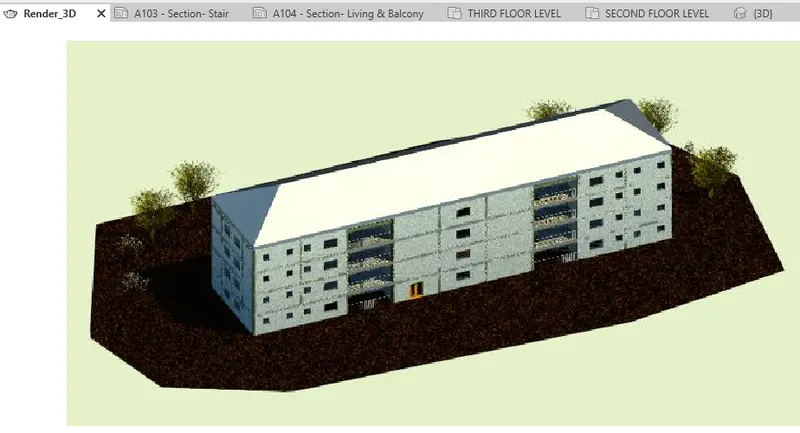
b. Rendering from out showing topographic features
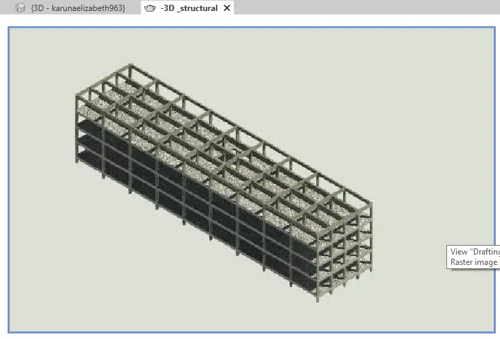
c. Rendering through structural framing
AIM:- Using the Rendering settings, Render images of the 3D model produced and include the rendered images to the drawing sheets
a. Rendering from interior rooms
b. Rendering from out showing topographic features
c. Rendering through structural framing
INTRODUCTION:- Renderred images gives the photorealistic image of the model. Render images gives various images such as lighting, etc.
PROCEDURE:-
- In project browser, select 3D camera view of the living room.
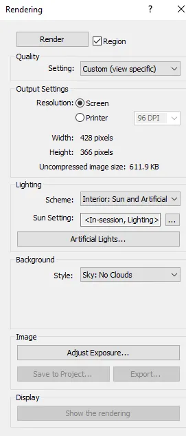
- Under view tab, select Render icon to create a realistic image of the model.
- Set rendening image as shown below. Then click Render.
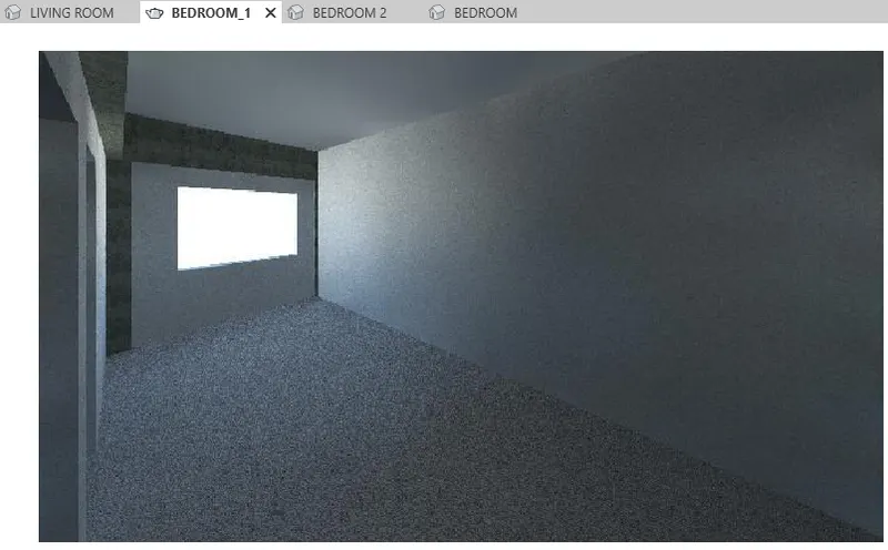 RENDERED IMAGE OF BEDROOM
(In this rendered image, due to some software error, furniture positioning is not seen)
Rendering from out showing topographic features
Rendering through structural framing
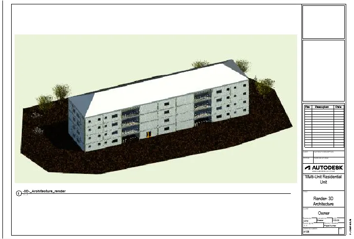 Rendered 3D images to the drawing sheets
RESULT:- Hence, using the Rendering settings, Rendered images of the 3D model produced and include the rendered images to the drawing sheets
7) Print the set of drawing sheets created and submit the drawings from the architecture and structure model
AIM:- To print the set of drawing sheets created and submit the drawings from the architecture and structure model
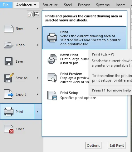
INTRODUCTION:- Under File icon, select print to print vaious sheets.
PROCEDURE:-
- Under File tab, select Print option to print the sheets.
RESULT:- Hence, showed to print the set of drawing sheets created.