Creating Architectural and Structural model with 3D rendering using REVIT
1) Select the type of structure you want to build from one of the three below:
a. Multi-Unit Residential Apartment
b. Office Buildings
c. School
Aim : To select type of the structure for modelling in the Revit software.
Introduction :
- Depending upon the type of structure the design consideration of building for the modelling purpose vary.
- So it is important to clarify the type of structure before starting any project so that it will serve its functionality for which it is being modelled.
Procedure :
- Type of structure from above three is primary school building which is classified as educational building for every 5000 population as per national building code 2016.
- It is G+1 educational building.
Result :
Therefore type of structure is selected as school building for modelling in the Revit.
2) Assume reasonable assumptions for geographic and location details for your project modeling. Based on assumptions and type of structure selected identify the modeling requirements from NBC
Aim : To assume reasonable assumption and location details for the project and identify the modelling requirement from NBC.
Introduction :
- National building code provides the standards which should be followed while designing any type of the model.
- It provides minimum standards which should be provided for different type of structure for different locations so that it serves its functionality optimistically without violating environmental and safety measures.
- Likewise for school building NBC provides the minimum standards for area, height, thickness of wall etc.
Procedure :
Assumptions for geographic and location details and NBC 2016 requirement for project modelling are as follows.
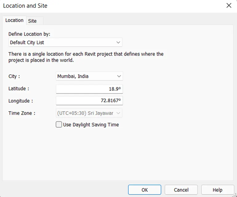
- Assume geographic location for project model is Mumbai India.
- As per National Building Code part 3 page no. 25 minimum land area per school is 0.4 ha.
- Minimum school building area is 0.2 ha.
- Minimum play field area inclusive of the limited parking requirement for functional uses is 0.2 ha.
- As per clause 12.3.1.1 part 3 of NBC Minimum ceiling height for educational building for all region is 3.6 m which is 12’.
- Minimum width provided for staircase for respective occupancies as per Fire and Life Safety code part 4 is 1.5 m for educational building.
- As the total height of building is 40’6” I e 12.3 which is less than 15 m so there is no need to provide the lift.
- In Revit software we can set the location using manage tab, using location tool of the project location panel.
- By clicking it we can set the location for the project as shown below.
Result :
Therefore, location for building is assumed as Mumbai India, and also based on assumption and type of the structure selected modelling requirements of NBC are identified above.
3) Using the structural model, include the following components based on the type of structure selected
a. Foundation – Isolated / Wall/Matt Foundation
b. Columns
c. Beams Connected to Columns
d. Roof Framing/ Truss
e. Floor / Decks
f. Floor Openings for Elevators and Stairs
Aim : To include the foundation, columns, roof framing, floor, floor opening in structural model in Revit software.
Introduction :
- The components such as foundation, columns, beams, floors are the structural elements of the model which carry various kinds of loads coming on the structure.
- Such structural framing elements can be added in the model using the structural template in the Revit software.
Procedure :
Step 1
- Open Revit software, select the structural file linked with the architectural template created last week and open it from home page of Revit software.
Step 2
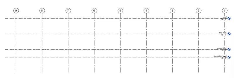
- Go to structure tab, select the level tool from datum panel, select pick line tool from draw panel and add the levels by specifying offset distance at required position as shown below.
Step 3
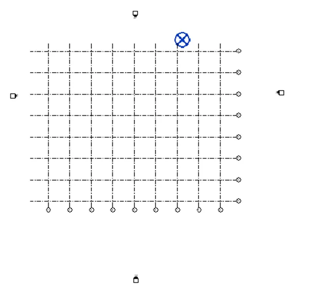
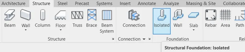
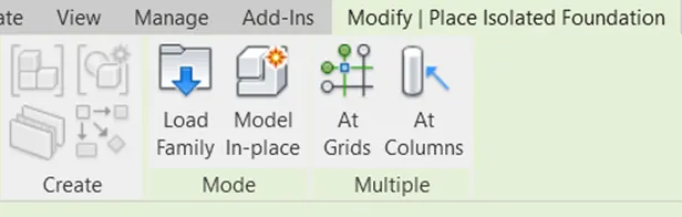
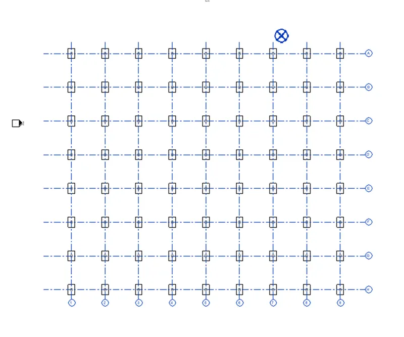
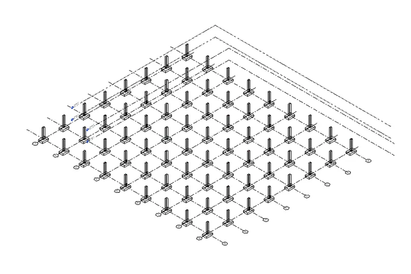
- Go to site plan view, select isolated footing from foundation panel of structure tab, select at grids option from place isolated foundation tab and select the grids by dragging the mouse and select finish from multiple

Step 4
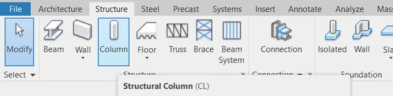
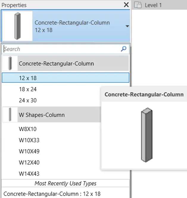
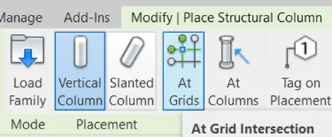
- For creating the columns, go to column tool from structure tab, select the column type as concrete rectangular column of size 12 x 18 and change the depth of column as -6’ from properties window.
Step 5
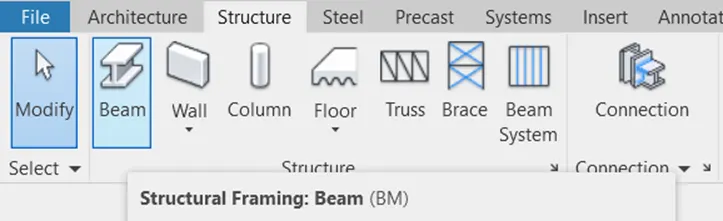
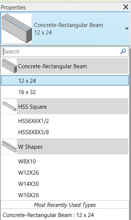
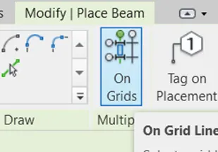
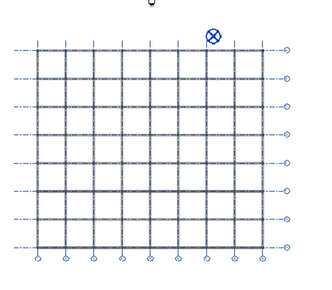
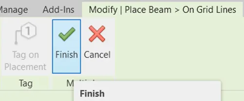
- Go to structure tab, select beam tool, select concrete beam from property window, select on grids option from place beam tab, select the grids by dragging with mouse and select finish from multiple panel.
Step 6
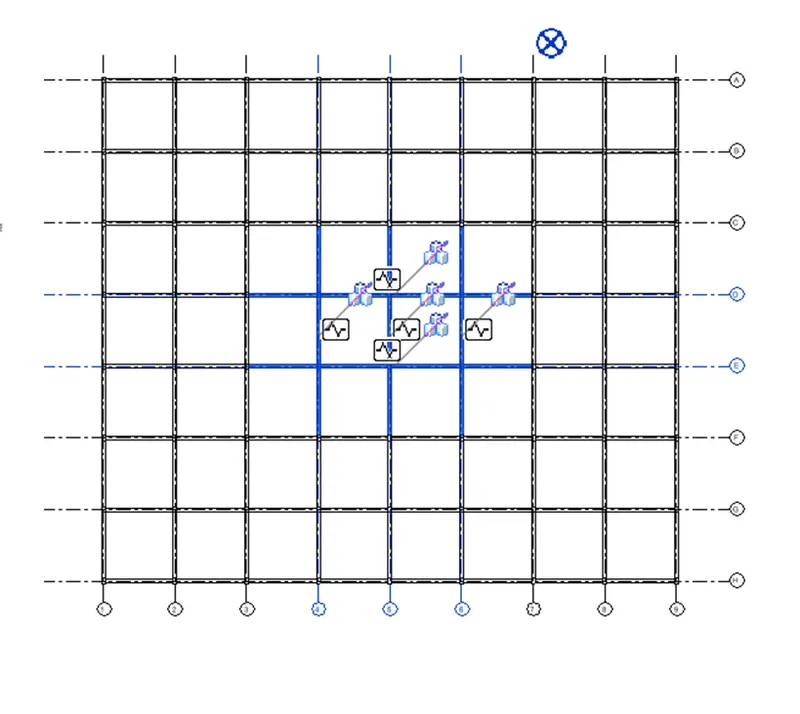
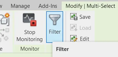
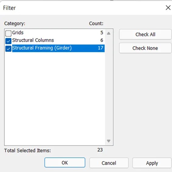
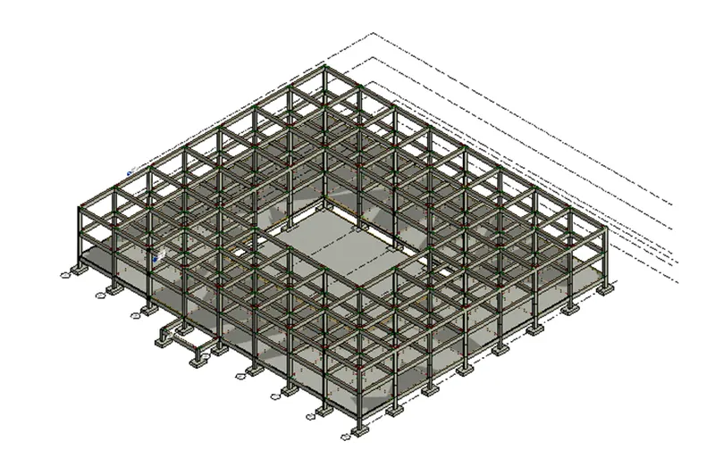
- Select the middle portion of plan, select filter tool from multi-select tab, uncheck grid option and delete key to delete it.
- Similarly delete the foundation from middle portion.
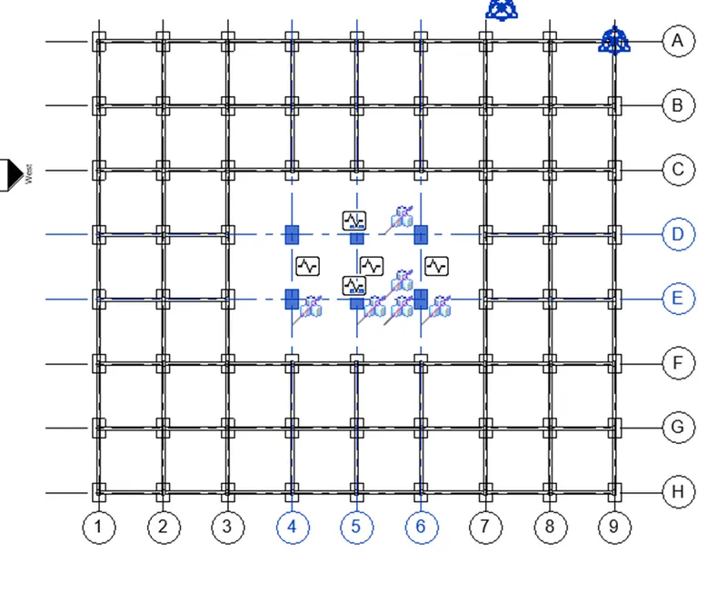
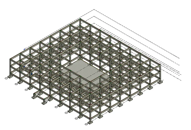
- 3D realistic view is shown below.

Step 7
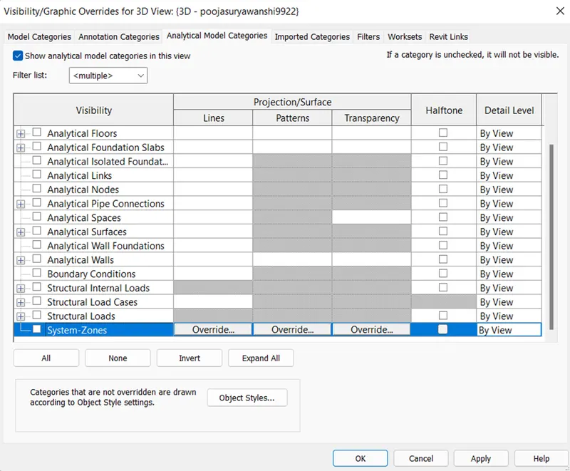
- To hide analytical lines, type VG command, uncheck all analytical model category visibilities from dialog box, select apply and ok.
Step 8
- Again, select column and create column at ground floor by selecting height option from modify toolbar of column and height up to first floor as shown below.

Step 9
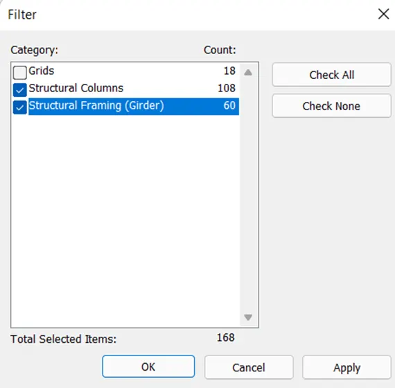
- To create the beams and column at the first ang ground floor, go to ground floor plan, select all componenets by draging with the mouse, select filter tool, and select the stuctural column, structural framing from filter dialog box.
Step 10
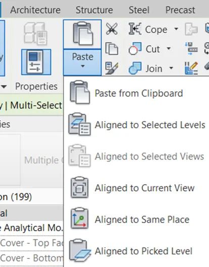
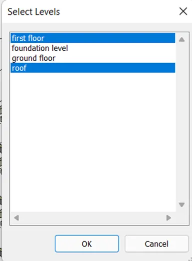
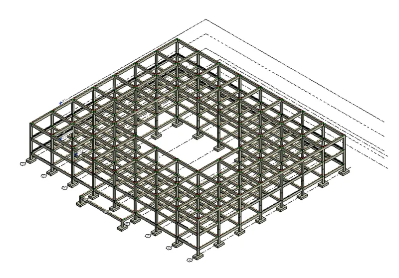
- Select the copy from clipboard panel and select paste option, select the aligned to selected level option, select the first floor and select ok.
Step 11
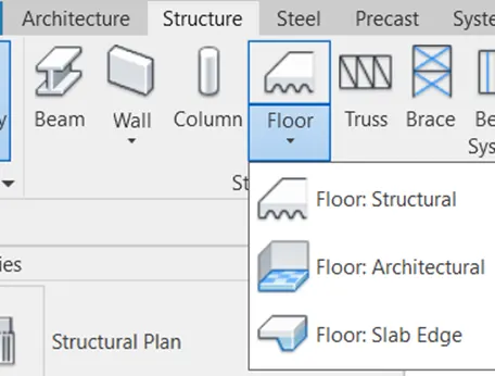
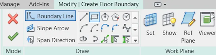
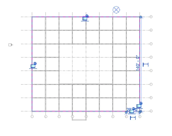
- To draw the floors, go to site floor plan, select the floor tool from structure tab, select rectangle tool from draw panel and draw the roof as shown below by changing the height offset of roof as 3”.
Step 12
- Similarly create the roof at ground floor as shown below.
Step 13
- For creating the shaft opening go to shaft tool from structure tab, select rectangle tool from draw panel and draw the shaft as shown below.
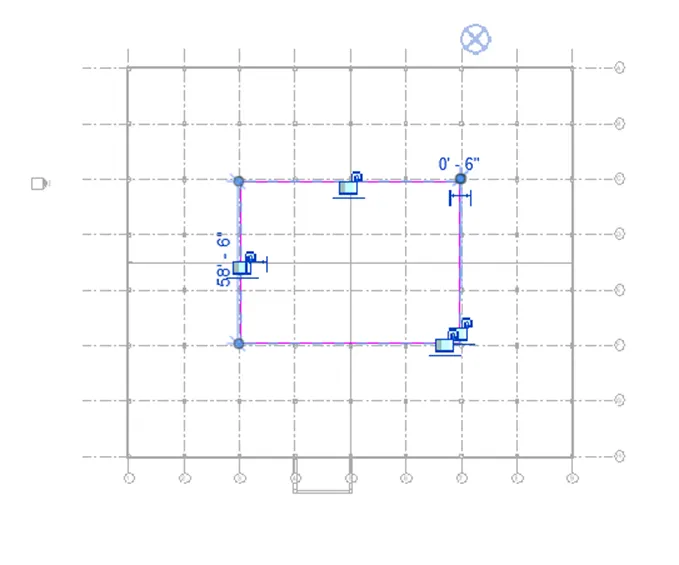
Step 14
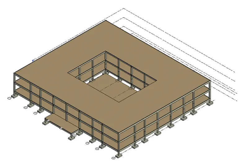
- Similarly go to ground floor plan, select the floor and copy it to first floor and at roof using copy and paste tool of clipboard panel and align it to the selected level as shown below.
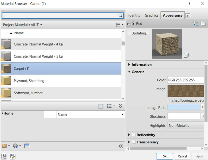
- Select the floor, select edit type from property window and change the material of the floor as carpet as shown below.
Step 15
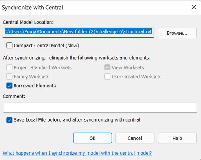
- Go to synchronize with central option from top toolbar and select ok.
Step 16
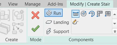
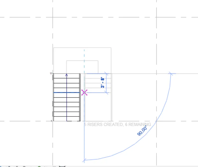
- Open the architectural file, select stair tool from circular panel, select the run and draw the stairs of width 5’ by changing width to 5’ using property window as shown below.

Result
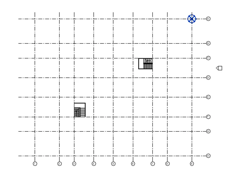
- Therefore, all the structural components such as footing or foundation, columns, beams, floors and stairs are created in structural and architectural file as shown below.
4) Using the architectural model, include the following components based on the type of structure selected
a. Wall Layout with appropriate material and finishing
b. Exterior façade with fancy finish
c. Interior partition walls to size rooms
d. Components to add details to a room ( Desk, Chair, Lighting, Plumbing fixtures)
e. Add components such as stairs Elevators
f. Have at-least one side of the building with curtain walls and glass panels
g. Include interior and exterior lighting fixtures
h. Place proper topographic components from outside ( Trees, Parking, Plants) to add details to the model
Aim : To include the architectural components such as walls, exterior façade with fancy finish, partition walls, components adding details to the model, stairs, interior and exterior lighting fixtures, topographical components outside the model in the Revit software.
Introduction
- Architectural elements such as walls, doors, windows etc., can be added in the model using the architectural template.
- Revit is a BIM software where we can add the minor details to make the model more realistic to utilize or make more efficient space management without making any compromises in the future.
- Such details may include desk, chairs, lighting etc.
- In Revit we can also add the topographical features which can be helpful to estimate the excavation or cutting cost even before starting the project.
Procedure :
Step 1
- Open the architectural file from home page of Revit software to add the architectural components.
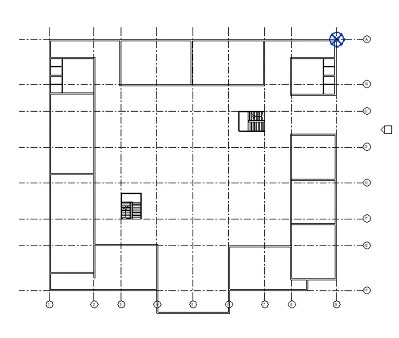
- Select the walls tool from architecture tab, select wall type generic 12” from property window and draw the walls at required position as shown below.
Step 2
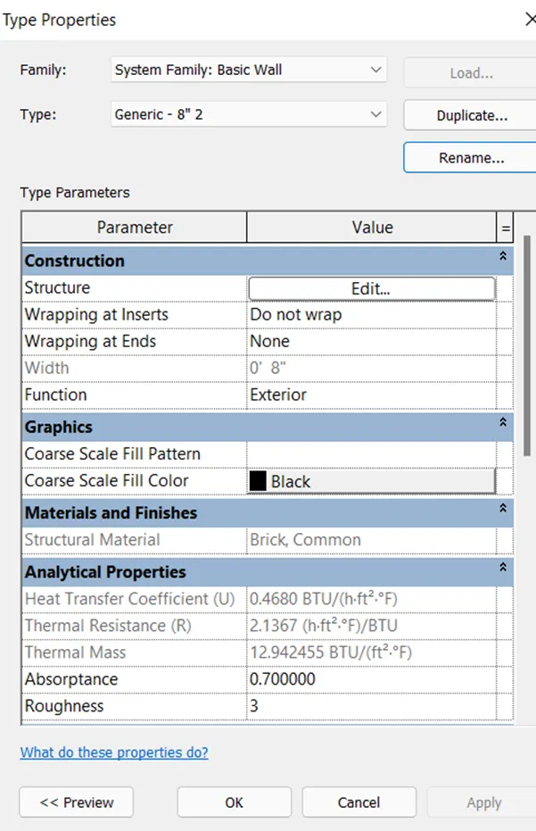
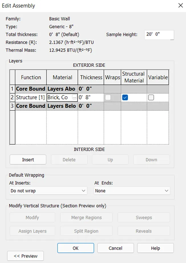
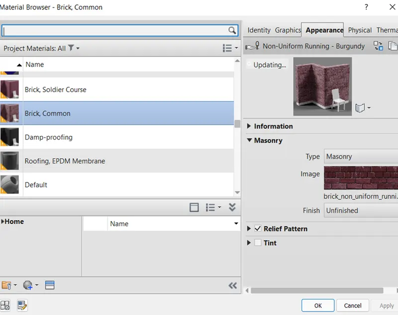
- Select the wall by using the filter tool, go to edit type from properties window, duplicate wall type and select the wall material as brick common and select ok as shown below.
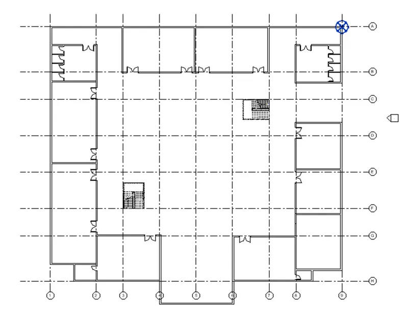
Step 3
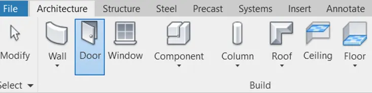
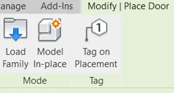
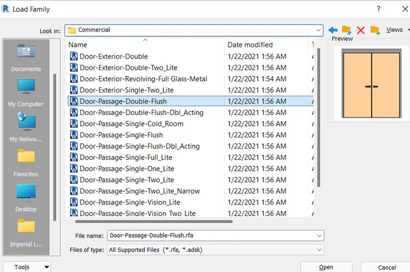
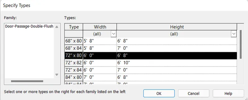
- Go to architecture tab, select door tool from build panel, select load family from mode panel of place door tab and place the doors at required position as shown below.
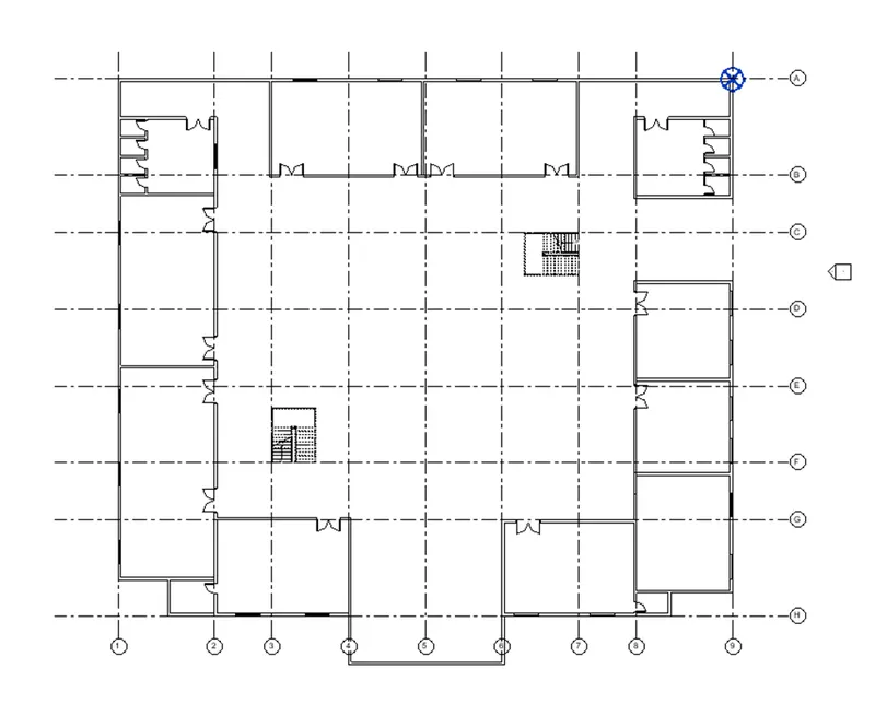
Step 4
- Similarly add the windows to all the rooms at the required position as shown below.
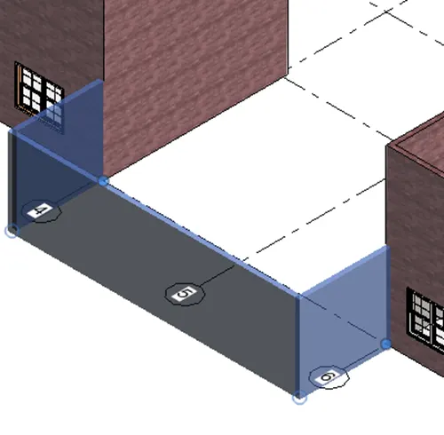
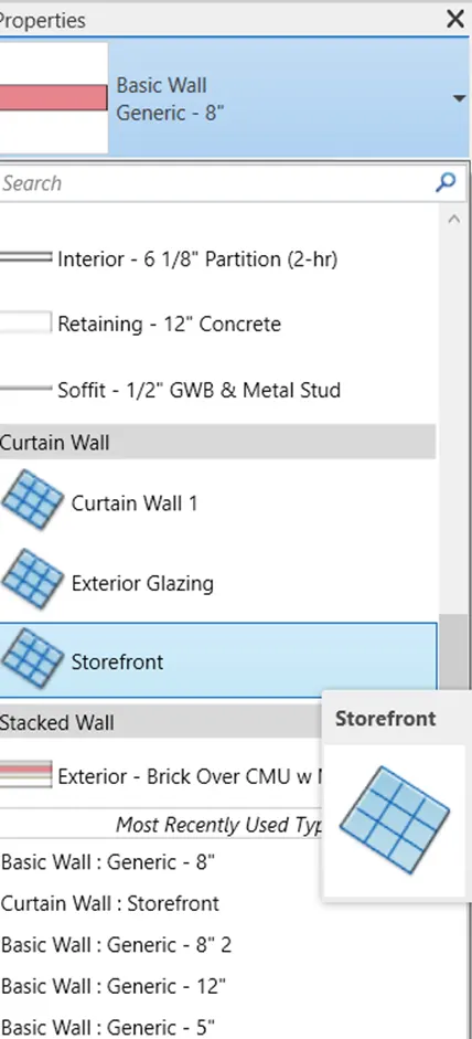
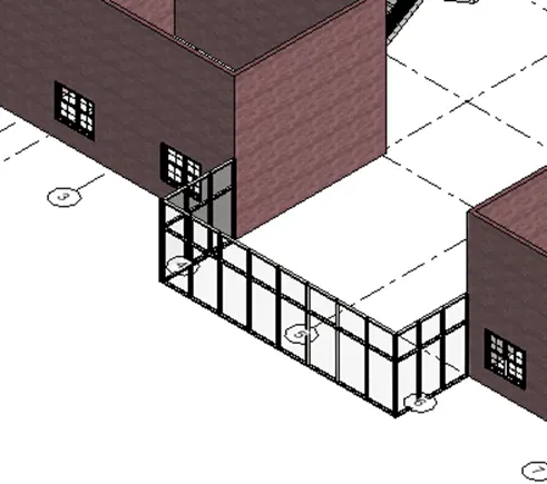
Step 5
- For adding the curtain system, select the front wall which is required to make as curtain wall, select drop down of basic wall type, and change the wall type to storefront as shown below.
Step 6
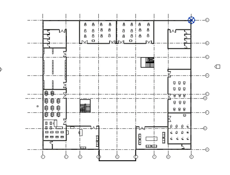
- For adding the components such as desk, go to architecture tab, select the component tool from build panel, select load family option and load the desk and add it in the model at required position as shown below.
Step 7
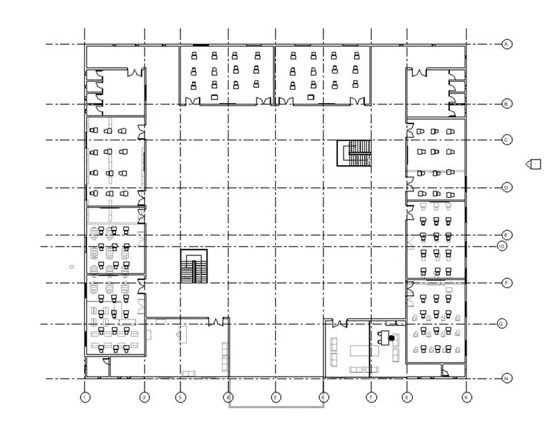
- Similarly add the component in the first floor plan as shown below.
Step 8
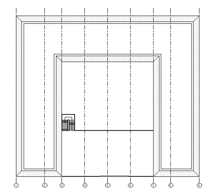
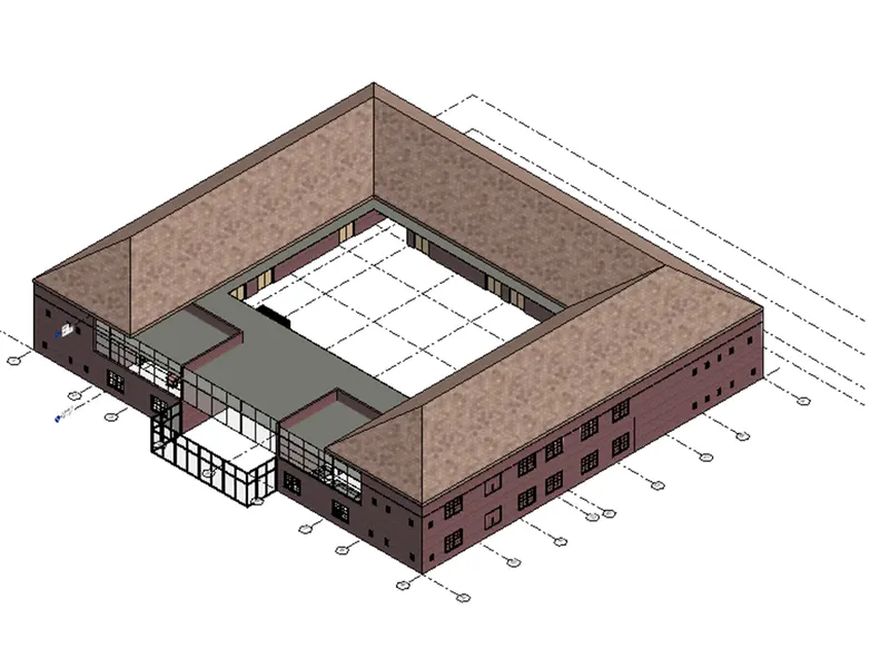
- For adding the roof, go to architecture tab, select the roof tool from build panel, select roof by footprint, select pick line or line option and draw the roof on the first floor plan by specifying offset distance as 12’ from the level as shown below.
Step 9
- Go to architecture tab, select the ceiling tool from build panel, select sketch ceiling and add the ceiling at the height of 11’ from ground floor and first floor as shown below.
Step 10
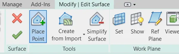
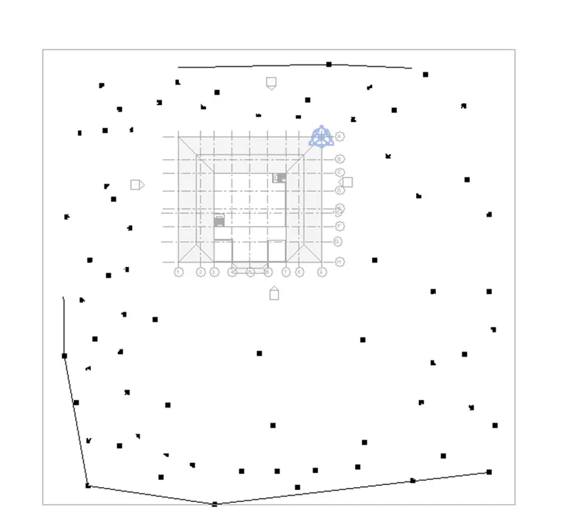
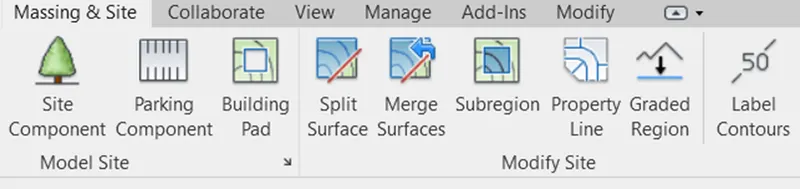
- For adding the topographical components, go to massing and site tab, select the

Step 11
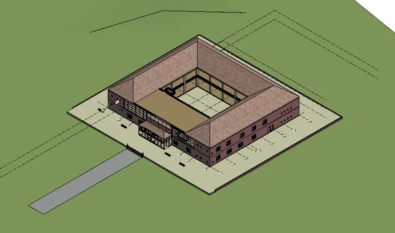
- For drawing the building pad, select the building pad tool from modify massing and site tab, select rectangle tool from draw panel and draw the rectangular building pad as shown below.
Step 12
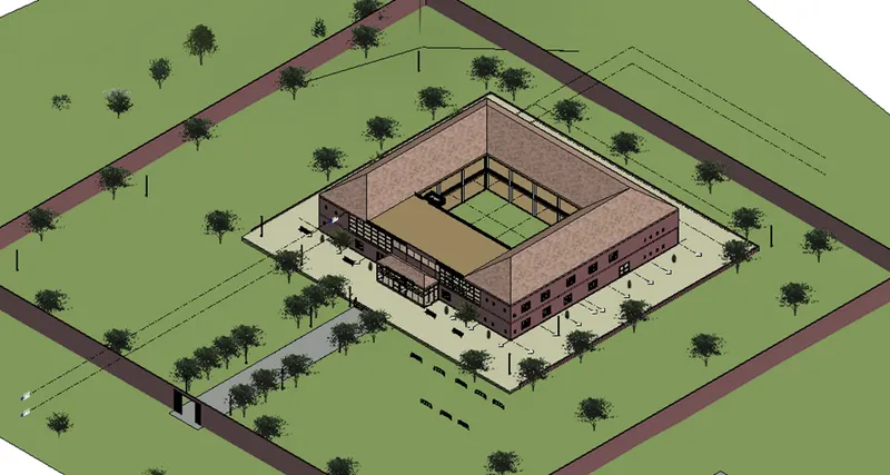
- Go to architecture tab, select the component option and load the site components such as tress and place at the required position as shown below.
- Again, go to wall tool from architecture tab, select the wall type and draw the wall as a compound wall and insert gate opening as shown below.
Step 13
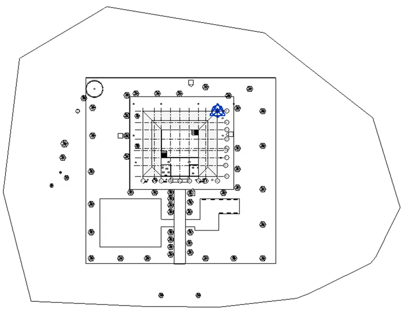
- Again, go to site plan view then go to massing and site tab, select the subregion tool from modify site panel, and subdivide the region to add playground.
- Select edit type from properties window and change the materials of the region to smooth sand.
- Similarly divide the region to add the parking area as shown below.
Result :
Therefore, wall layout with appropriate material and finishing, interior partition walls, components adding details, stairs, lighting, stairs, and topographical components are added in the model as shown below.