Project 1 _Creating an Architectural plan for the provided plot size and develop relevant basic structural drawings
Project 1 _Creating an Architectural plan for the provided plot size and develop relevant basic structural drawings
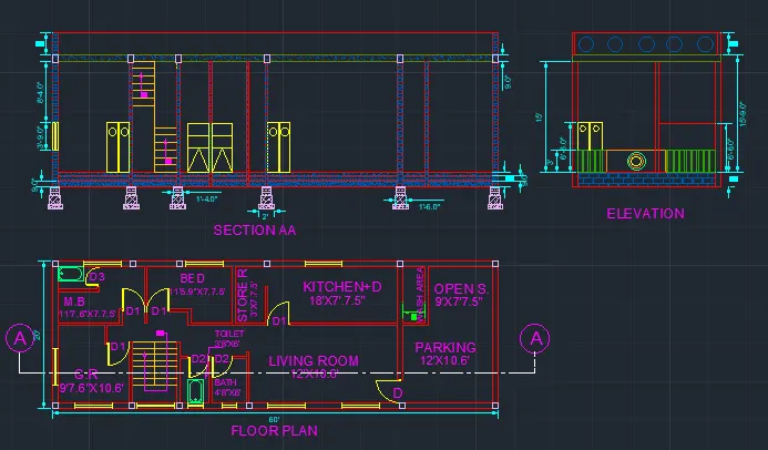
AIM: Develop Architectural Drawing like Floor plan, Elevation & Section plan
Introduction: Design and Draft a layout of a residential building with the following details:
a. Plot Size: 60’x20’(18.3m x6m), b. Orientation- Facing East
By using auto Cad 2019 in that using drawing and modify(editing commands) like line, text, layer, dimension, offset, circle etc etc.
all dimensions in feet, inches (Engineering)
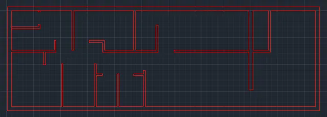
Pocedure: Floor Plan
1step)
start auto cad as imperical set unit as engineering
then set scale as 1:100
go to layer property and select layer as wall and gives red colour to it
then go for line command from ribbon or Line from dialog box
now we have arrange the plan with residential amminities in 60'X20' plot size
draw horizontal line of 60'
and one verticle line with 20'
then take OFFSET command and offset both line by 9" as wall thickness towrds inner side
then go to bottom line and offset from privious offset line as a distance of 10'6" for first room with 4.5" internal wall thickness
now second offet from last line with 7'7.5" with 9" external wall thickness
then go left bottom portion and offset from internal line towards right at a distnce of 9'7.6" with 4.5" internal wall thickness
then again offset for stair case at 6' with 4.5" wall thickness
again take offset at a distance of 3'8" with 4.5" internal wall for toilet
then offset of 4'8" with 4.5" internal wall for bath
again offset of 12' with 9" external wall for Living Room
now for parking area offset of 12' with 9" external wall,
now, go left top portion and offset from internal line towards right at a distnce of 11'7.6" with 4.5" internal wall thickness
then again offset for bed room at 11'5.9" with 4.5" wall thickness
again take offset at a distance of 3' with 4.5" internal wall for store room
then offset of 18' with 4.5" internal wall for kitchen
again offset of 3' with 9" external wall for washing area
now for open space offset of 9' with 9" external wall
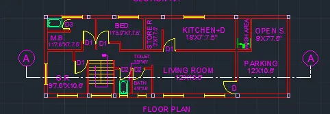
then go for door opening as shown in fig as per following dimensions
D= 3'3"
D1= 3'
D2= 2'8"
D3= 2'7"
then for toilet and bath length should be 6'
so draw blocks of 6' length with 4.5" internal walls
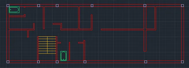
2step) column, plumbing symbol & stair case
go for layer proprty add layer as folloes
column = with colour 232,178,..
plumbing = 40
stair case = 110 colour code
choose a line command
draw a column of size 9"X9" (square column) at first right bottom corner
then copy the column get ortho off select interaction point and copy it
all the junction as per dwg
now for staircase select staircase proiperty from layer
select line
then draw a 6' horizontal line at first starting point then select OFFSET command
and offset line at a intervel of 0.82' offset it for 7 times for making 7 trads
then make flight of 6'X2'9" and draw middle line two make 2 flites of 3'
now for plumbing showing wc symbol
go to ADC command (autocad design center) in that go for en-symbol
then go to home and in that block
we show various home accesories symbol there
then choose WC symbol> insert block then set scale and take on wc room
and also copy on Master Bed room with proportion
3rd step) dimension, text, doors, window,ventilasion & section line
go for layer proprty add layer as folloes
dimension = green
text = magenta
doors & windoe = yellow
section line = white
choose a line command
make a window and doors
D= 3'3" w=5'X3'9"
D1= 3' v=2'X2'6"
D2= 2'8"
D3= 2'7"
for door, select door layer from layer property
draw a line of 0.75' and on that point draw a circle upto opposite wall
by using CIRCLE command and the from 0.75' wall draw perpendicular line upto circle edge and take offset 0.75' and joint it
and trim the extra circle edge by using TRIM command draw all circle according to size by using same method
only radius of circle vary according to size
then window, select same layer of door for window,
choose a line command
draw a mid line of room at outer wall offset it by 2'6" both the sides and remove middle line
then draw horizontal mid line between 5' vertcle line offset line by 1" on both side and cut middle line
and copy the window and draw every middle of the block
then take 2' ventilation bar toilet and bathroom
take same winow at middle of outer wall of toilet and bathroom and compact it for 2'
now text,
select text layer
give all text as shown is fig
by DTEXT command with proper size ( 0.18') height of text
then for dimensions
select dimension layer from layer property
and dimension to all things where its required by usind linear dimension command
and select prper size by Dimmenion property
then finally select section line from layer
select dash short dash line layer
and draw it by 25scale size as section AA line
Procedure: Elevation
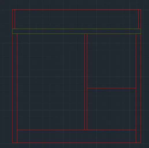
1st step) walls and slab
selct wall layer from layer property
draw horizontal wall by choosing line command
then draw vertcle line of 20'9" as ground to parapet height
then go to bottom line
take OFFSET command and offset it by 2' as plinth height then
offset it by 6 ft as wash room area wall height
then again offset of from last line at a distance of 9' as slab level
then againn offset of 9" as slab thickness
then again offset from last line as parapet height
then go for verticle line
select offset command offset line by 9" as wall thickness
then offset for first room at distance of 10'6" with 4.5" internal wall thickness
then again offset with 7'7.6" as secont romm with 9" external wall thickness
then trim the extrala lines by using trim command
2nd step) parapet design, dimensions, filler material(plinth), text, door & gate
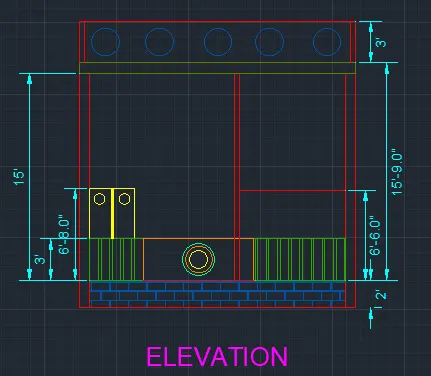
select a design layer from layer property
and draw a circle by using tan tan tan and draw a proportinal circle
and copy it and paste with uniform sapcing
then draw fillier material by selecting filler material layer
then go to HATCH command selct brick work
and paste it an plinth area with 25 scale
then draw door by selecting door layer from layer command
and draw door of 6'6" height with 3'3" width
draw a centerline of door and offset 5" both the side for glazed of door
and draw a circle as design purpose at one side and mirror it for other side
then selct layer for text
by DTEXT command written a name of dwg
then go for dimension layer
and from annotation select linear dimension and show the dimension
then draw gate of height 3' with using diffrent layer and gives design as architectural purpose
Procedure: Section AA
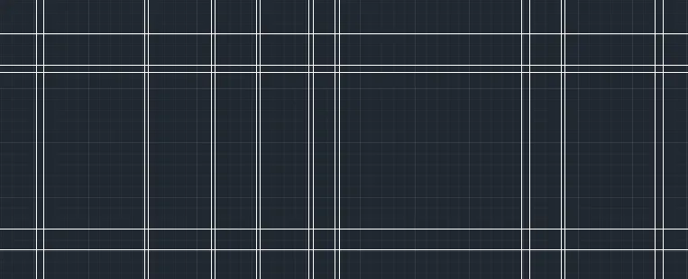
1st Step) construction line
choose a construction line from ribbon or by enterting XLINE on dialog box
the draw a horizontal construction line according to elevation in that all heights are included
then draw verticle construction lines as refrence of floor plan where after cutting section those lines are visbile
2nd step) draw walls, doors and windows and pinth steps
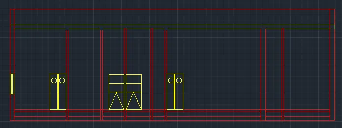
choose wall layer from layer property
then draw all walls by refrecing construction line
then same door and window
select door and window layer from layer property
draw it by using construction line refrence
draw only those doors & window whoose visible after cutting the section through section line
and also show slab by using slab layer from layer property
3rd step) stair case, footing, filler material, text, dimensions & walls material, slab material(concrete)
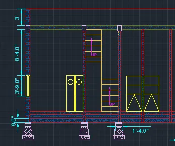
go for stair case layer select it
then choose line command from ribbon
draw a stair case first draw a mid line which divides the two flight(1st & 2nd flight)
then draw 1 horizontal ine in right flight at bottom
then give 1' height as riser and offset it by 1' and make as 6 riser because in section line cut 4 trade so 5 riser are visible in cutting section
then gon for second flight same 5 riser make from top(sab level) at a distance of 1' each
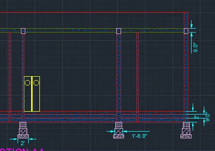
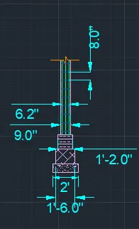
then go for footing
select column and footing layer from layer property
and draw step footing of size 1'4" with 1'6" height
then 2 nd footing with 1'6" with 1'6" height
then draw final layer of PCC with 1' height and 2' width
then copy for all columns
then fill it by filling material using HATCH command
then by using HATCH also fill plinth, wall and slab with appropiate hatch
then selct layer for text
by DTEXT command written a name of dwg
then go for dimension layer
and from annotation select linear dimension and show the dimension
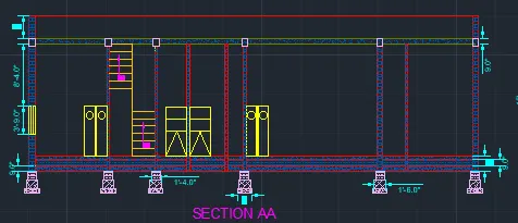
Result : we draw a architectural plan having 60'X20' plot size, by 9" & 4.5" external and internal wall respectively, with 15ft height of single storey building, all procedure and details brefly mensioned above
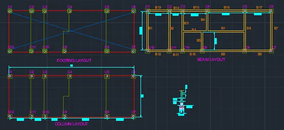
2) AIM: Draw a Structural Drawing (Column, Bean, Footing Plan)
Introduction: Design and Draft a layout of a residential building with the following details:
a. Plot Size: 60’x20’(18.3m x6m), b. Orientation- Facing East
By using auto Cad 2019 in that using drawing and modify(editing commands) like line, text, layer, dimension, offset, circle etc etc.
all dimensions in feet, inches (Engineering)
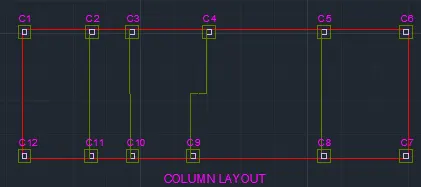
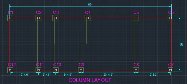
Procedure: Column Layout Plan
go for wall line layer
draw a rectangle by using rectangle from draw command
rectangle of size 60'X20' plot size
then selct column line layer
draw column of 9"X9" at every corner as per shown in floor plan
then select other layer for projection of beam and outer of column as PCC showing
then by using text command text or naming the all columns C1,C2 .... like that
2 step): go for dimension layer command
and gives all required dimension
and finaliseed column layout plan
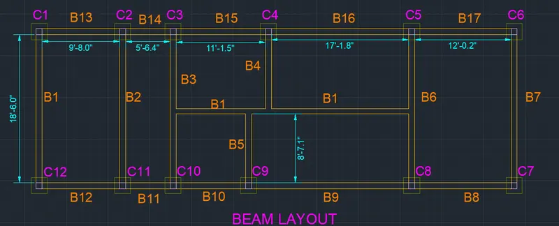
Procedure : Beam layout plan
go for beam line layer
draw a rectangle by using rectangle from draw command
rectangle of size 60'X20' plot size
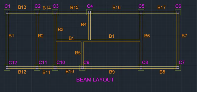
offset as 9" for width of beam at every beam
then selct column line layer
draw column of 9"X9" at every corner as per shown in floor plan
joint all beam layers with column
and by using text command give all name of column and beam as
B1,B2... like that for beam & C1,C2.... like C1,C2.. etc
2 step): go for dimension layer command
and gives all required dimension
and finaliseed beam layout plan
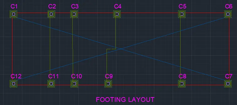
Procedure: Footing Layout Plan
go for wall line layer
draw a rectangle by using rectangle from draw command
rectangle of size 60'X20' plot size
then selct column line layer
draw column of 9"X9" at every corner as per shown in floor plan
then select other layer for projection of beam and outer of column as PCC showing
then by using text command text or naming the all columns C1,C2 .... like that
then draw steps footing by uing diffrent layer from layer property
draw 1st layer of 1'4" around the column
and 2nd step og 1'6" size arround the column
and copy it for all column
and draw cross line as footing plan
2 step): go for dimension layer command
and gives all required dimension
and finaliseed footing layout plan
column footing section for refrence
Result : we draw structural plan of 60'X20' plot, (colum layout plan, footing layout plan, beam layout plan & section of column fotting) by using various commands like text, dimension, line, offset & layers etc etc, all breif detail and procedure is above