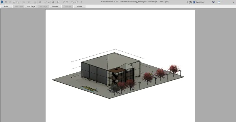
Creating Architectural and Structural model with 3D rendering using REVIT
Q1)
AIM:Select the type of structure you want to build from one of the three below:
a. Multi-Unit Residential Apartment
b. Office Buildings
c. School.
ANS) OFFICE BUILDING
Q2)
AIM :Assume reasonable assumptions for geographic and location details for your project modeling. Based on assumptions and type of structure selected identify the modeling requirements from NBC.
PROCEDURE :
1. My project is in plain area. it is in commercial area and road width infront of my structure is 70ft and it is a office building.
MODELLING REQUIREMENTS FROM NCB ARE:
2. An exit must be provided in every building so as to permit safe escape of employes in case of earthquake or fire hazards.
the minimum height of basement should be 2.5m and maximum height should be 4.5m.
Q3)
AIM:Using the structural model, include the following components based on the type of structure selected
a. Foundation – Isolated / Wall/Matt Foundation
b. Columns
c. Beams Connected to Columns
d. Roof Framing/ Truss
e. Floor / Decks
f. Floor Openings for Elevators and Stairs
PROCEDURE:
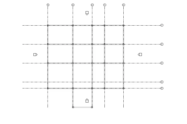
1. Open revit and make horizontal and vertical grids at spacing of 30' as per ncb.
2. Go to the elevation and increase the number of levels upto roof and change their names.
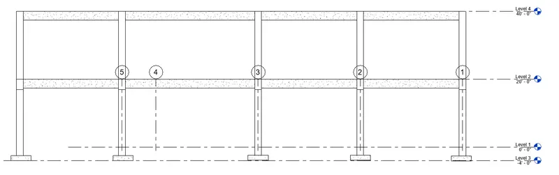
3. Select column from ribbon and place the columns at intersection of grids as shown.
4. Change the view to 3d ,you get an interface as shown.
5. Place another column on the grid intersection from ground floor to first floor.
6. Now select beam from the ribbon and connect this beam to different columns as shown. change the view to 3d.
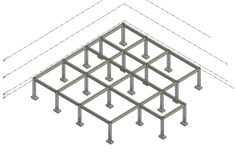
7. Now go to isolated option from the ribbon and place them on the different columns as shown. change the view to 3d.
8. Select the entire figure and go to the copy option and assign them to first floor and second floor.
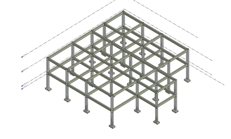
9. Now go to the roof option and change the view to ground floor and select points and make a loop and assign them
to first and second floor and change the view to 3d.
10. Now go to the wall option and select the floor you want to assign the wall ,copy it and assign to different levels.
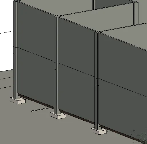
11. change the front wall to curtain wall as shown in figure.
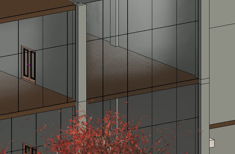
12. From the properties option change the colour and material of roof and walls. lets make a roof to place stairs, go to the floor option and draw a rectangle in the plan ,change the view to 3d
and copy it to different levels.
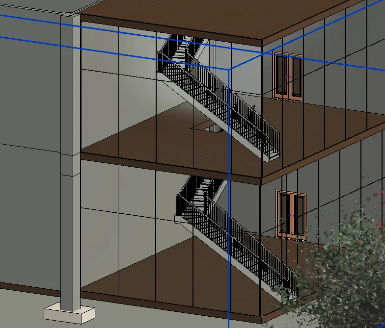
13. Draw a shaft and make stairs in that as shown in figure,copy and place to different floor levels.
and make doors at the entrance of stairs.
Q4)
AIM : Using the architectural model, include the following components based on the type of structure selected
a. Wall Layout with appropriate material and finishing
b. Exterior façade with fancy finish
c. Interior partition walls to size rooms
d. Components to add details to a room ( Desk, Chair, Lighting, Plumbing fixtures)
e. Add components such as stairs Elevators
f. Have at-least one side of the building with curtain walls and glass panels
g. Include interior and exterior lighting fixtures
h. Place proper topographic components from outside ( Trees, Parking, Plants) to add details to the model.
PROCEDURE:
1. With the same grids drawn in the previous plan draw a wall along the boundary.
2. Draw the interior partitions and place the required furniture and components in the plan and change the
view to 3d.
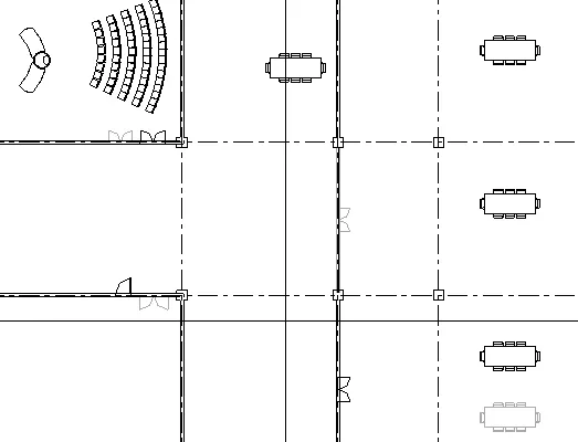
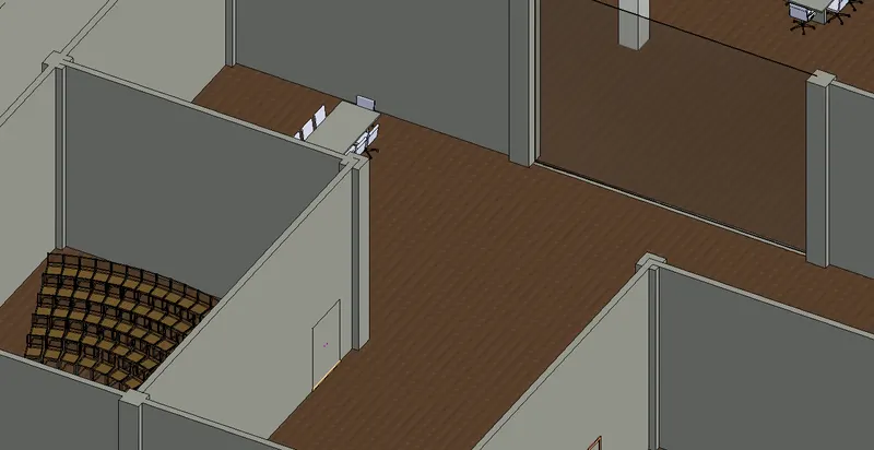
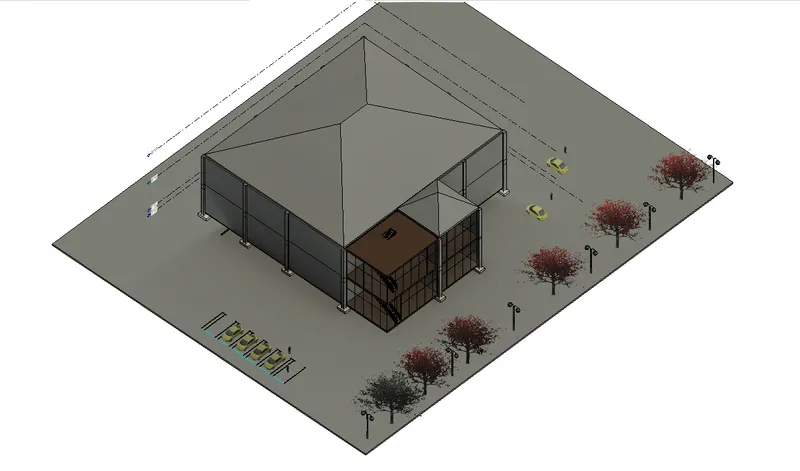
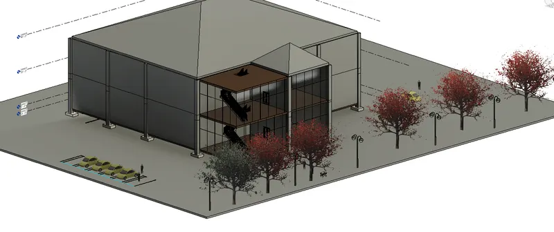
3. Change the front walls of the building with curtain walls or glazed panel as shown in figure and copy the entire figure and place it to the first floor.
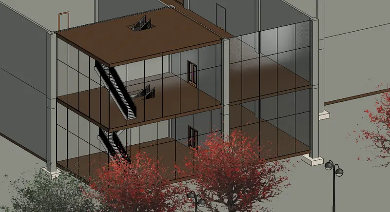
4. Draw the roof by making a rectangle along all the sides of second floor.
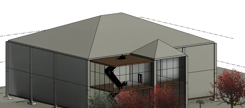
5. Now go to the plan view and draw a rectangular floor and view it in 3d as shown.
6. Go to place a component and add the required components from the library and place it in the figure.
Q5)
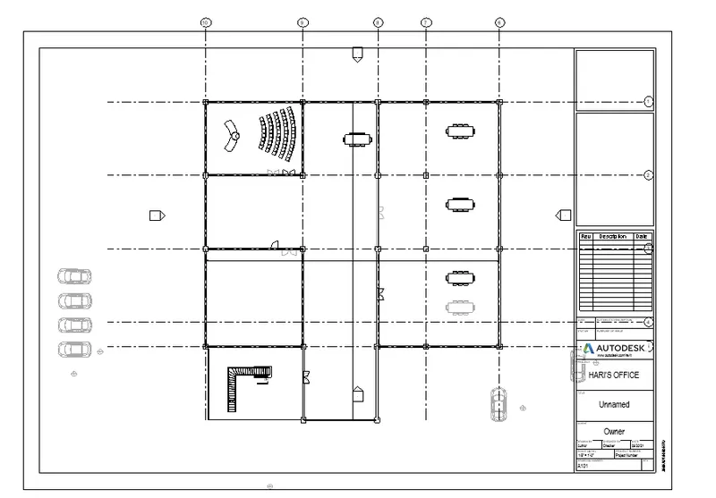
AIM : Provide a set of drawings in an architectural and structural model to list the following details with categories and appropriate sheet templates included
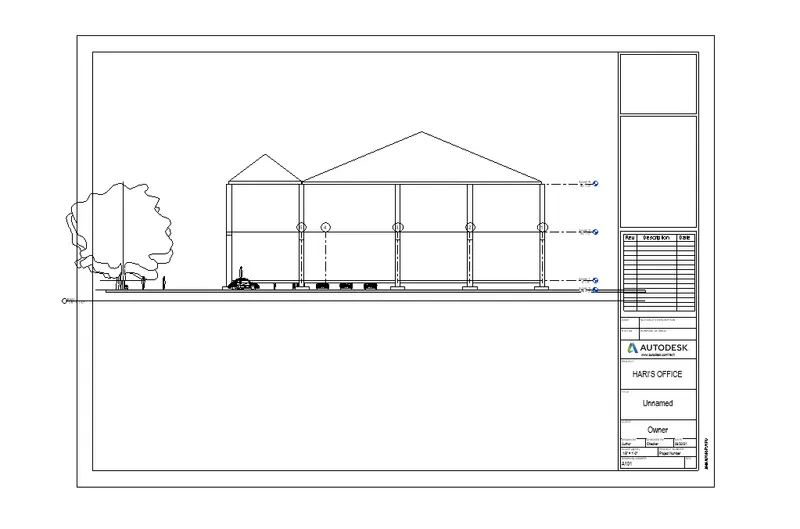
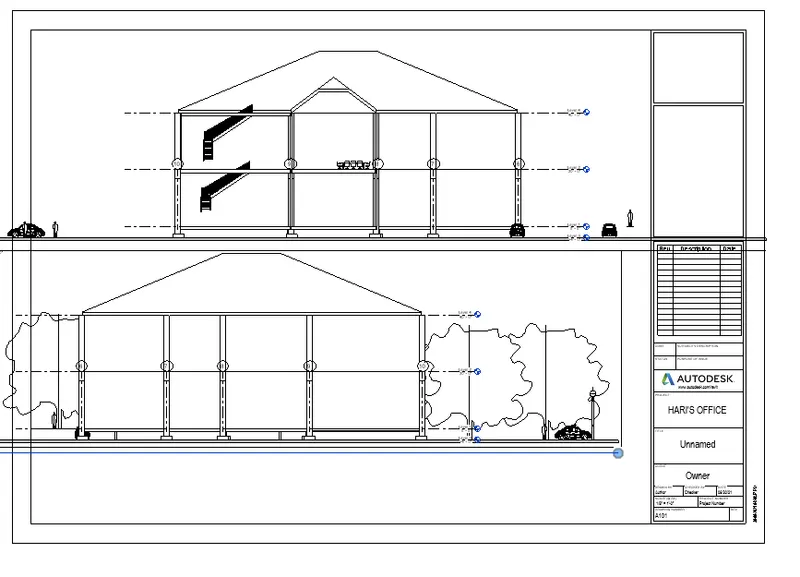
a. Floor Plans with Annotations
b. Elevations
c. Sections
PROCEDURE:
1. The sheet option ,as the sheet opens there is another option below it called views and select the required view you want to place.
Q6)
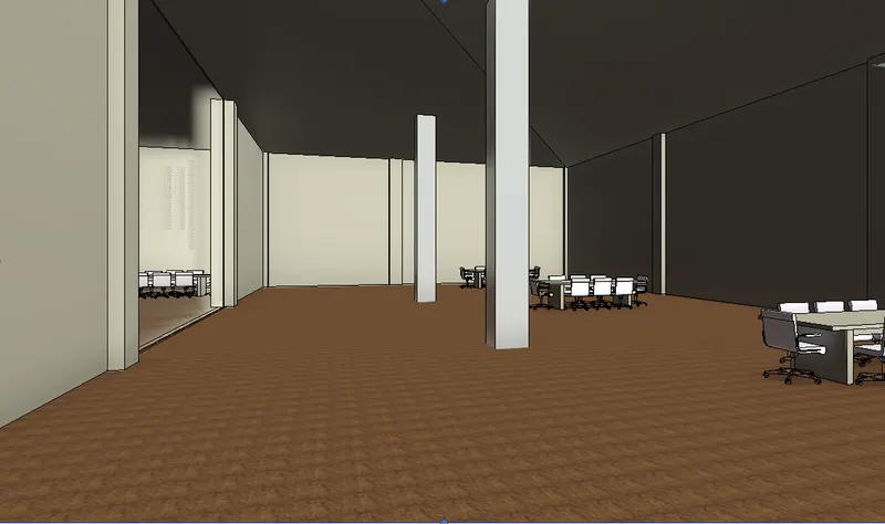
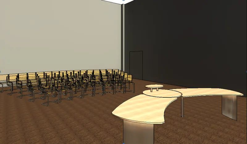
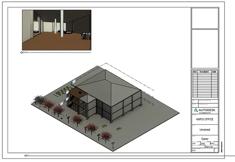
AIM: Using the Rendering settings, Render images of the 3D model produced and include the rendered images to the drawing sheets
a. Rendering from interior rooms
b. Rendering from out showing topographic features
c. Rendering through structural framing.
PROCEDURE:
1. In order to render any figure go to the render option from the ribbon and change the settings you want
and click render figure will turn to realistic as shown below.
7)
AIM: To Print the set of drawing sheets created and submit the drawings from the architecture and structure model.
PROCEDURE:
1. Click the views and open file menu and click the print.
2. Print dialog box is appear.
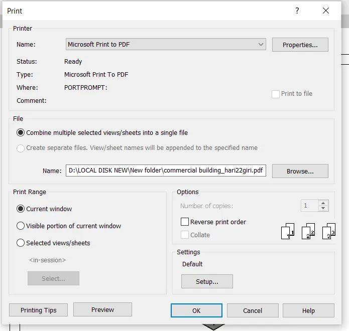
3. Then, change the settings of sheets size ,texts styles page setup everything.
4. Then click print and press ok.
RESULT:
Finally, set of drawing sheets created and submit the drawings from the architecture and structure model.