Creating Architectural and Structural model with 3D rendering using REVIT
INTRODUCTION: Revit enables the project to be completed in a combined effort. Structural engineers that are using Revit and are working with architects using Revit Architecture can directly link to the architectural model. Linking a revit architectural file with a revit structure file gives structural engineers a starting point for their design, based on the architects design intend. Changes made by architects can be tracked facilitating design coordination and change management. Similarly, architects using Revit architecture can link revit structure model into their architectural modelsand reap the same coordination benefits.
Architectural model of a building may include walls , doors, windows, stairs etc. contributing to the entire aesthetics of the structure whereas the structural model may include fountation, column, beams, truss works, connections etc. that contributes to the structural stability of the building. These two models can be developed separately and can be linked together to a single model i.e, the construction model.
1. Select the type of structure you want to build from one of the three below:
a. Multi-Unit Residential Apartment
b. Office Buildings
c. School
Multi-Unit Residential Apartment
2. Assumptions for geographic and location details for your project modeling
- My building is constructed in the residential area.
- My building is constructed in the plain area (geographic)
- Infront of my building there is a road with the width of 30 feets.
- As per the NBC, the height limit will be given in NBC part V-1, (National building code).
- The size of the rooms also given in the NBC part V-1.
3. AIM : To include the following components based on the type of structure selected using the structural model.
INTRODUCTION:
- Beams and columns are two important types of structural elements that play a key role in creating a safe load path to transfer the weight and forces on a structure to the foundations and into the ground.
- Beams and columns could be built using the same shapes and materials but each serves a different function and is designed differently.
- A foundation is the lowest part of the building structure.
- It is the engineering field of study devoted to the design of those structures which support other structures, most typically buildings bridges or transportation infrastructure.
- It is at the periphery of Civil, Structural and Geotechnical Engineering disciplines and has distinct focus on soil-structure interaction
PROCEDURE :
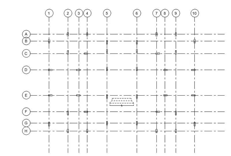
- first we draw the vertical and horizontal grids as shown below.
- Next we need to add the columns with the size of 200m x 600mm, as shown in the below figure
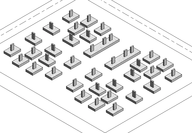
- select the fiundation type place to column
- The 3D view of the column and foundation is shown.
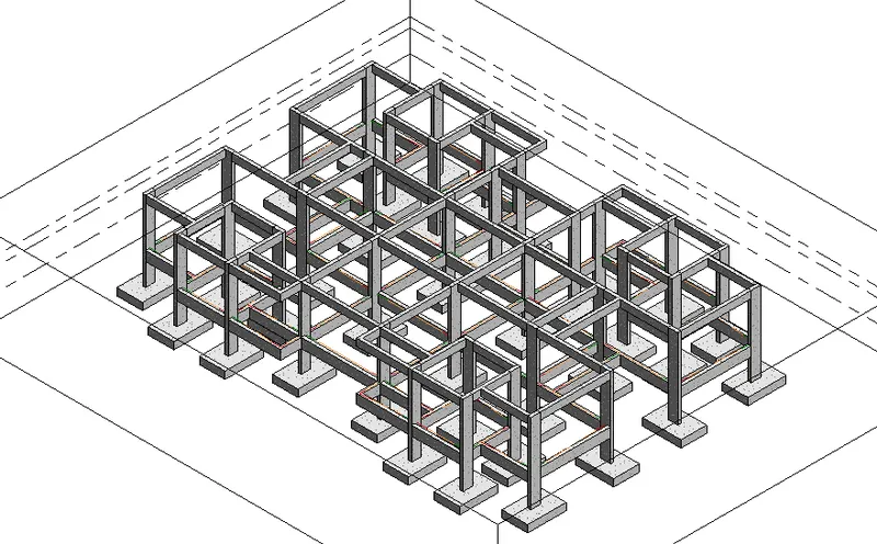
- The beams are added to the columns connecting each each other.
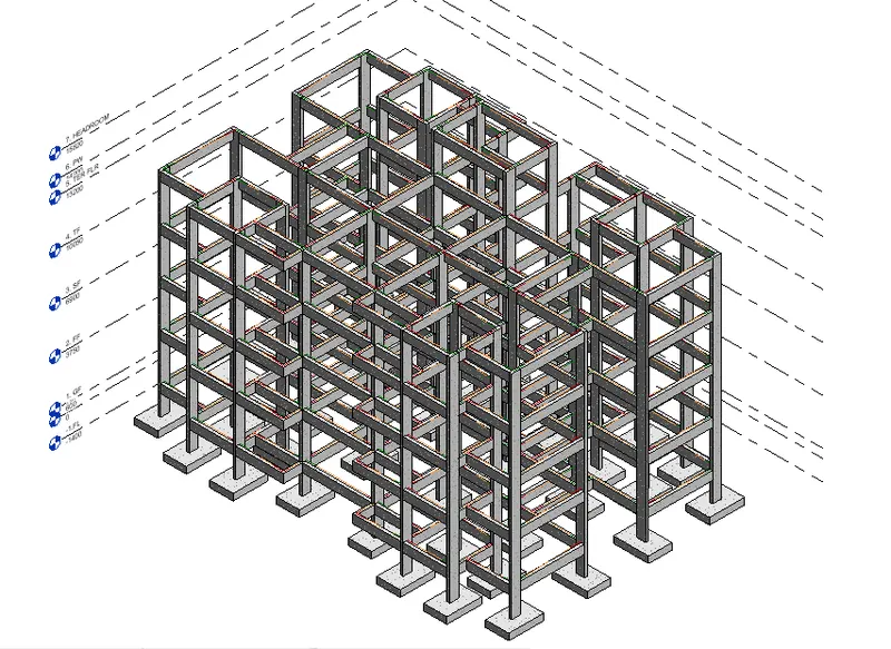
- The beams and columns of the created level is copied to the upper levels.
- The floor is created for each levels.
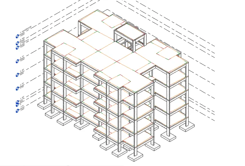
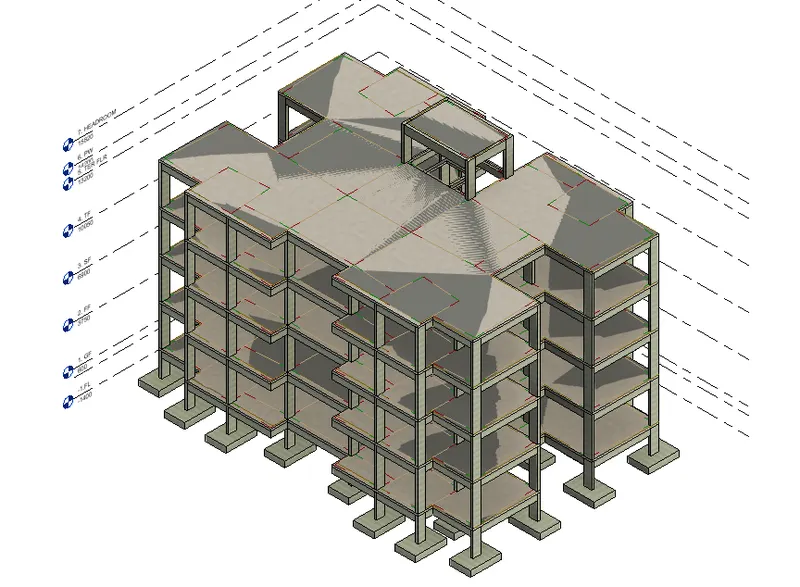
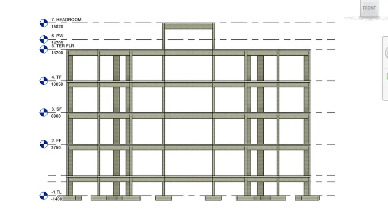
RESULT: The given components are created successfully using structural template in revit.
4. AIM : To include the given components based on the type of structure selected using the architectural model
INTRODUCTION :
- Partition-walls are a significant component of a building design. Without partition walls a building's plan cannot be decorative or structured
- Lighting fixtures, come in a wide variety of styles for various functions
- The most important functions are as a holder for the light source to provide directed light and to avoid visual glare.
- Some are very pain and functional, while some are piece of art in themselves
- Nearly any material can be used so long as it can tolerate the excess heat and is in keeping with salety codes
PROCEDURE :
- Create Wall Layout with appropriate material and finishing
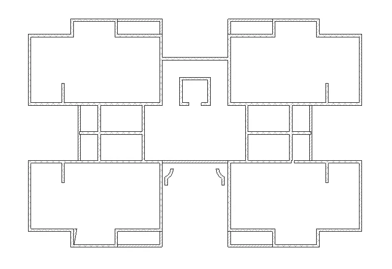
- Exterior façade with fancy finish
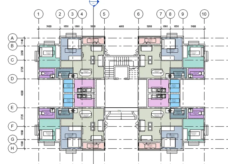
- Interior partition walls to size rooms
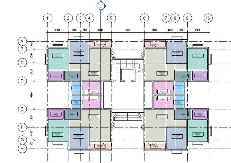
- Components to add details to a room ( Desk, Chair, Lighting, Plumbing fixtures)
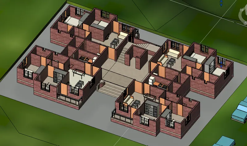
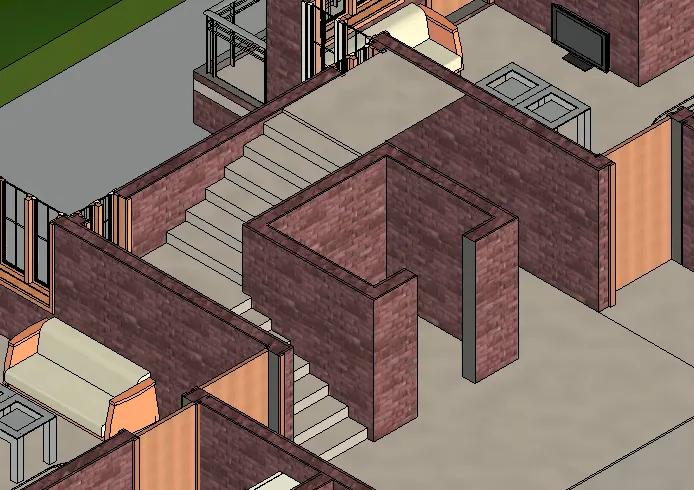
- Add components such as stairs Elevators
- Have at-least one side of the building with curtain walls and glass panels
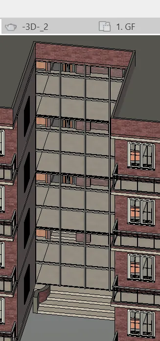
- Include interior and exterior lighting fixtures
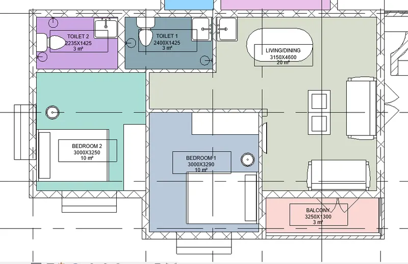
- Place proper topographic components from outside ( Trees, Parking, Plants) to add details to the model
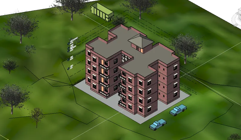
RESULT:
The given components are successfully inserted in the architectural model
5. AIM : To provide a set of drawings in an architectural and structural model to list the given details with categories and appropriate sheet Templates included
INTRODUCTION:
- Floor plans are the most critical element of your house plans Drawn to scale and shown from above floor plans illustrate how rooms. spaces, and physical features work in relation to each other within the home
- They're the key documents that show how people will move through the space and interact with their home Floor plans, show the extent to which a space will work for its intended purpose
- Al elevation is a view of a building seen from one side, a that representation of one view This the most common view used to describe the external appearance of a building
- Each elevation is Labelled in relation to the compless direction it Faces eg. looking toward the north you would be seeing the southern elevation of the building
- Sectional views, reveal hidden details in a mechanical drawing These views assume that a cutting plane of the object represented by the drawing displaying the appropriate section of the interior
PROCEDURE :
- Initially, provide the annotations to each level.
- provide the following in sheet templates:
- Floor Plans with Annotations
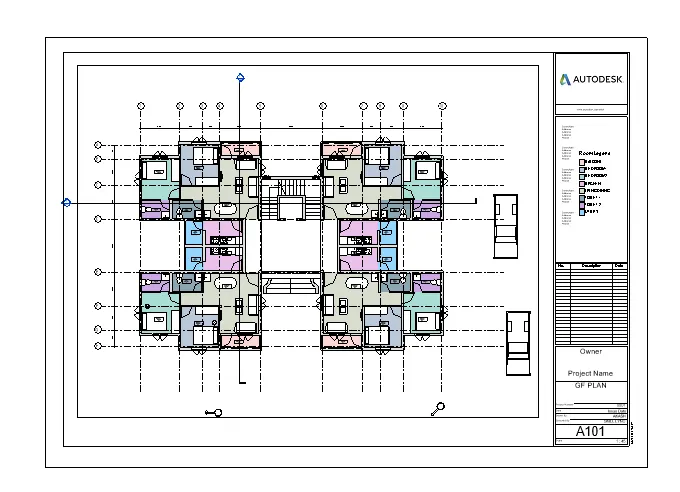
- Elevations
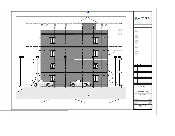
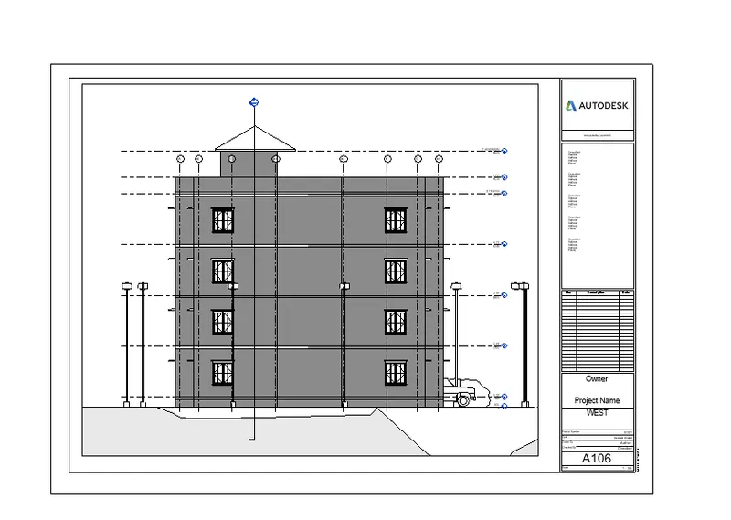
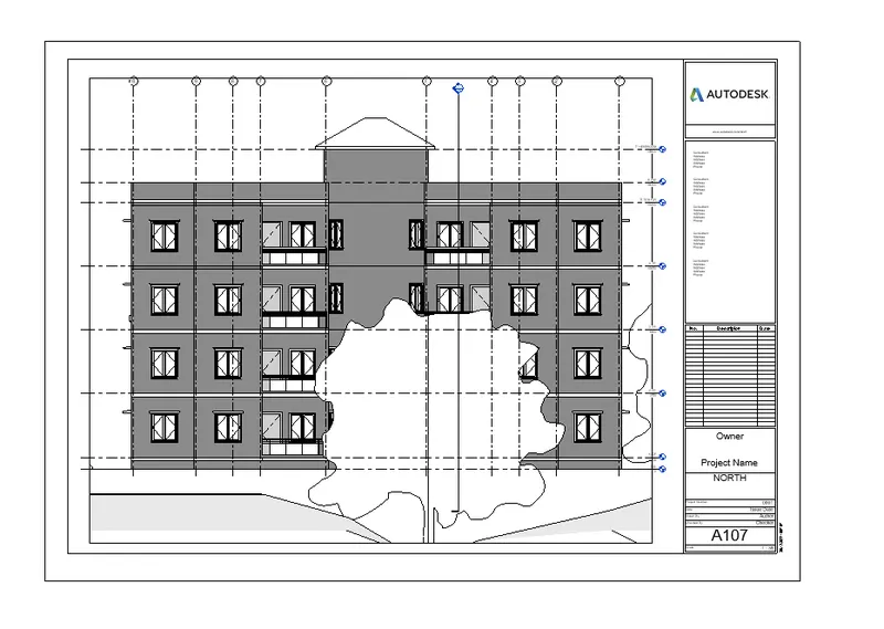
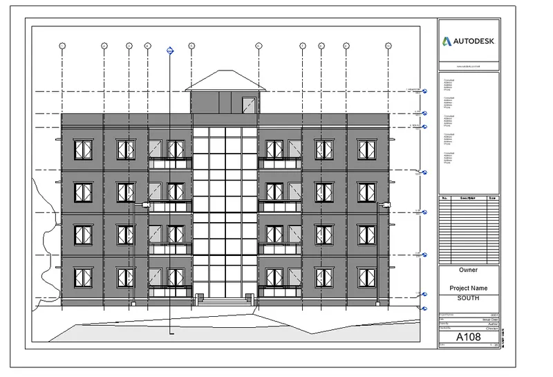
- Sections
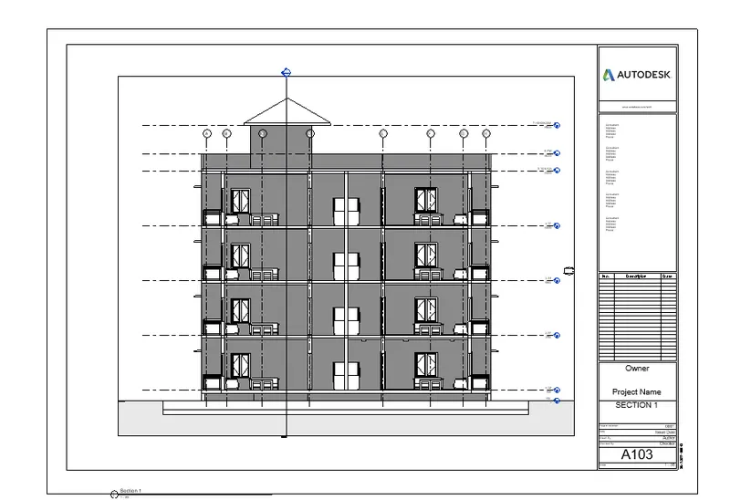
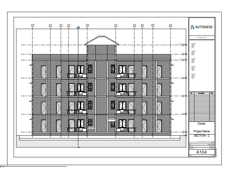
RESULT : All the requirements given in the questions like architectural and structural model are created successfully using revit.
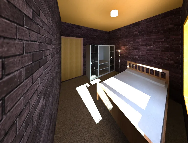
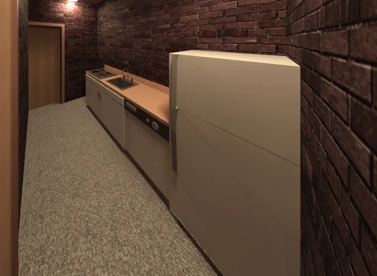
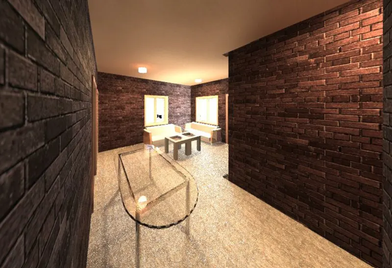
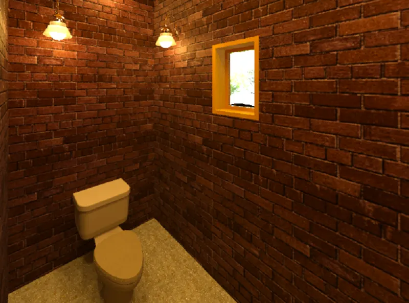
6. AIM : To create the rendered 3D images of the following and to include them in the templates:
a. Rendering from interior rooms
b. Rendering from out showing topographic features
c. Rendering through structural framing
INTRODUCTION:
- Render the view to create a photorealistic image of the 3D model
- After preparing the 3D view and using the Rendering dialog to select desired settings, click Render to render the age
- Revit begins the rendering process. rendering the entire image progressively. Revit displays a progress dialog, which allows information about the rendering process.
PROCEDURE:
- Initially, create the 3D rendered image of different interior rooms:
- To create the 3 D rendered image first go to view --> 3D view --> Camera.
- Then place the camera wherever required .
- Then in the view tab select render option to render the 3D image.
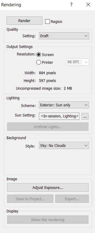
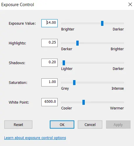
Rendering from interior rooms
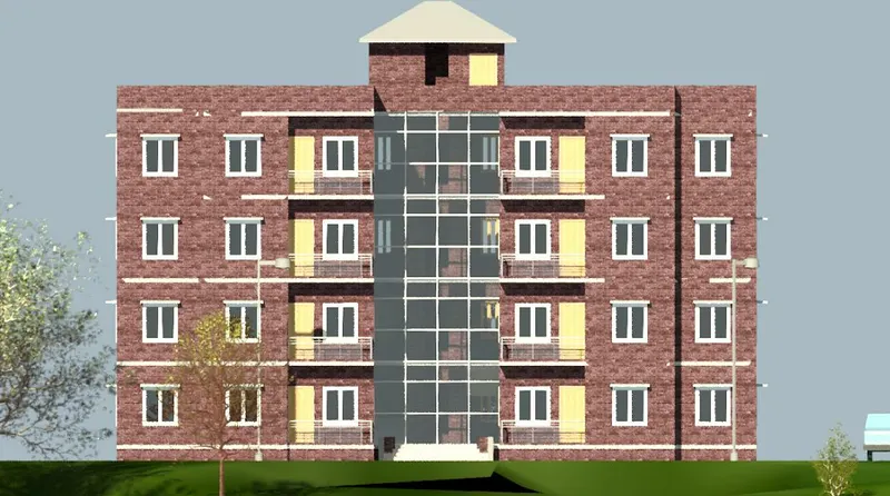
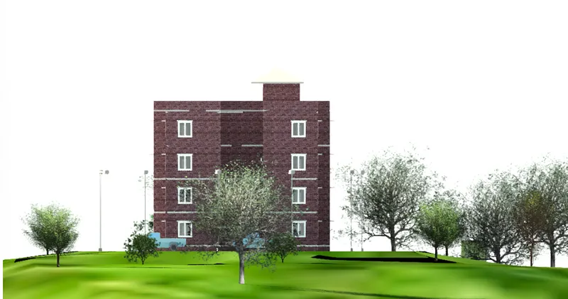
Rendering from out showing topographic features
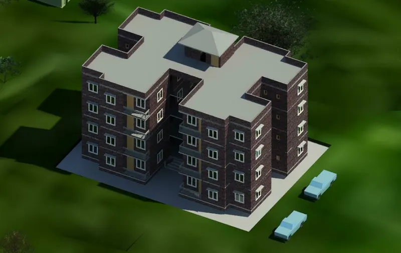
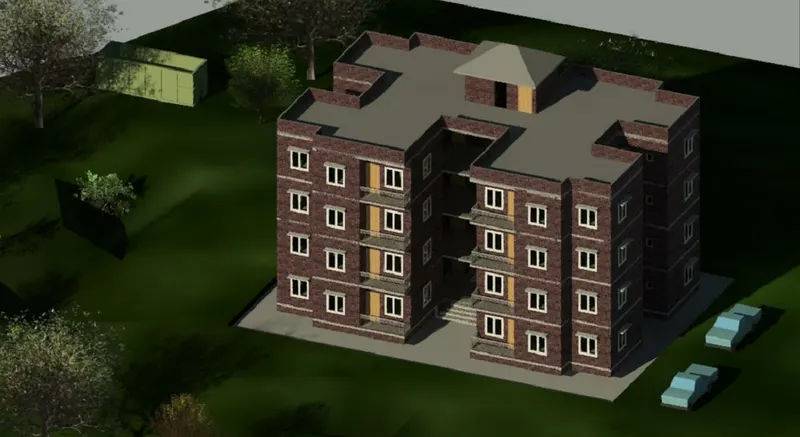
Rendering through structural framing
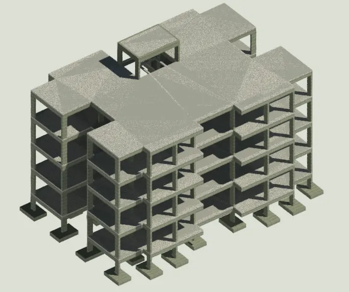
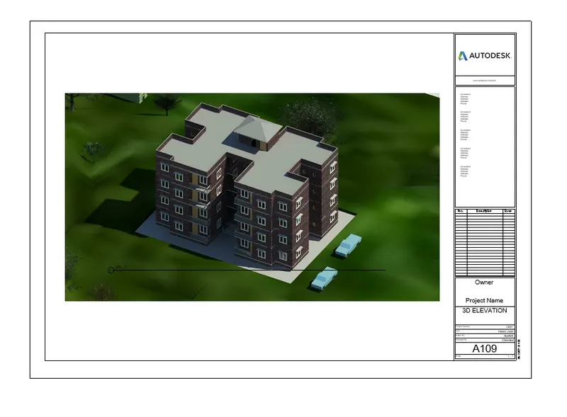
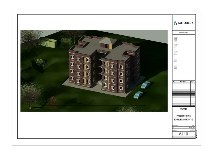
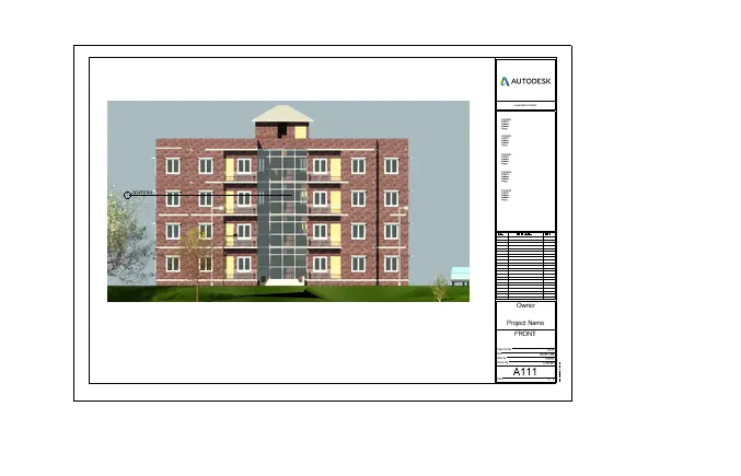
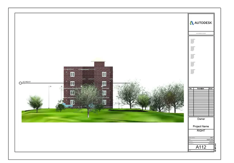
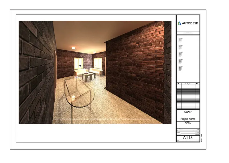
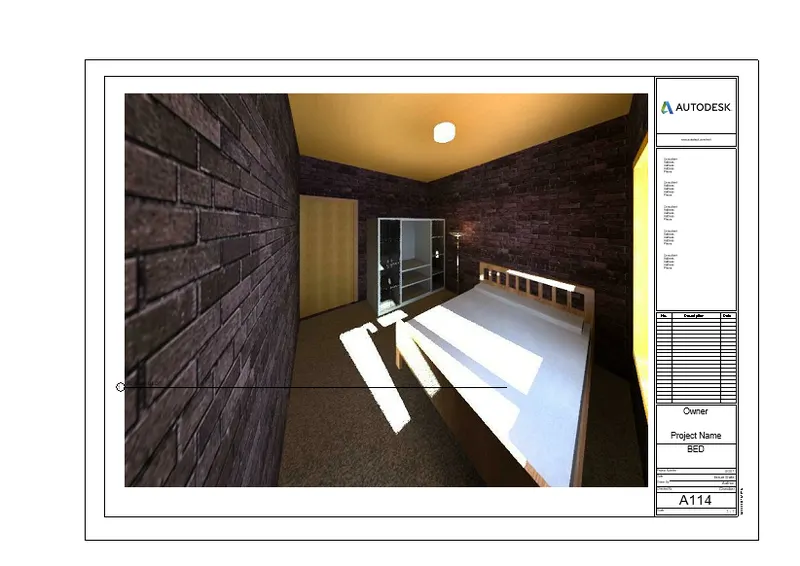
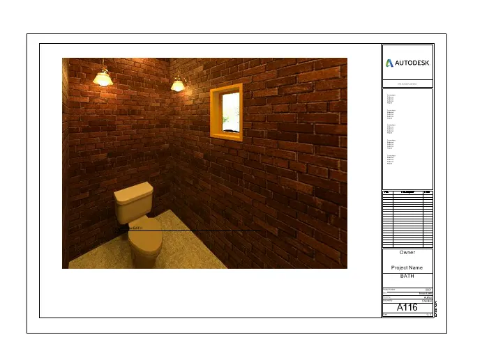

RESULT : All the rendered image of the 3D model is added to the sheet drawing successfully.
7. AIM: To print the set of drawing sheets created and to submit the drawings from the architecture and structure model
INTRODUCTION :
The Print tool prints the current window, a visible portion of the current window, or selected views and sheets - You can send the desired drawings to the printer to PRIV or PLT file, or to a PDF WE
PROCEDURE :
- First we use the print tool to print the drawings, as shown below.
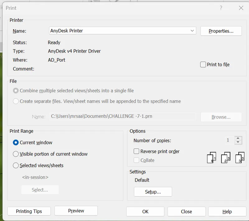
- After printing the drawings, we can print the drawing as shown below.
- Print pdf file are attched