Creating Architectural and Structural model with 3D rendering using REVIT
) Select the type of structure you want to build from one of the three below:
a. Multi-Unit Residential Apartment
b. Office Buildings
c. School
ANSWER 1:
The type of structure I have choose a Multi-Unit Residential Apartment.
2) Assume reasonable assumptions for geographic and location details for your project modeling. Based on assumptions and type of structure selected identify the modeling requirements from NBC
ANSWER 2:
The location of the project is Mumbai, Maharashtra
The geographic condition of the land is plain or flat
According to NBC the modeling requirements of the multi-unit residential apartment-
- It comes under the group A occupancy class
- Types of construction is TYPE 2
- The open space around the building is not less than 4.5m because the width of the road is 25’
- The height of building is not exceeded 1.5m width of the road
- The height of all room is not less than 2.75m
- The building is following the PART 4 fire and life safety
3) Using the structural model, include the following components based on the type of structure selected
a. Foundation – Isolated / Wall/Matt Foundation
b. Columns
c. Beams Connected to Columns
d. Roof Framing/ Truss
e. Floor / Decks
f. Floor Openings for Elevators and Stairs
ANSWER 3:
AIM:
By using structural template to create the multi-unit apartment building.
INTRODUCTION:
In the model we created foundation, columns, beams, roof, floor, opening for residential multi-unit apartment.
PROCEDURE:
STEP 1) CREATE MODEL FOR PROJECT
- Open Revit software
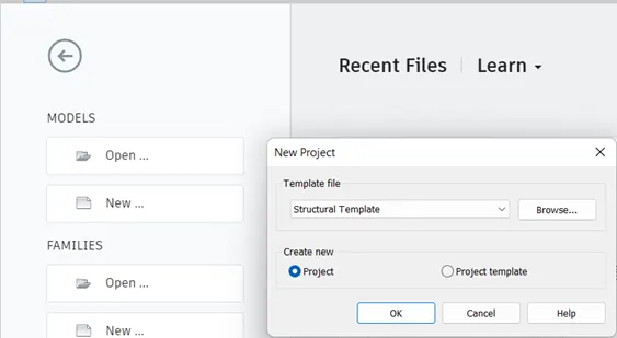
- Select new model from Revit home interface
- Choose structural template>OK
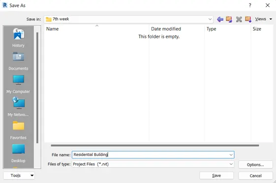
- From the file tab save the model with appropriate folder and name
STEP 2) CREATE GRID AND LEVEL
- From the project browser select any direction under the elevation
- Go to structural tab select levels from datum panel
- Create required level for the building and rename the level
- From the project browser open foundation plan under the structural plan
- Go to structural tab select Grids from datum panel
- Create transvers and longitudinal grid and rename it
-
STEP 3) CREATE ISOLATED FOUNDATION
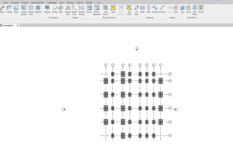
- Open foundation level floor plan form project browser
- Go to structural tab select isolated from foundation panel
- From property browser edit the footing size according to my building
- Placed 3 different sizes of footing according to size of column
-
STEP 4) CREATE COLUMN

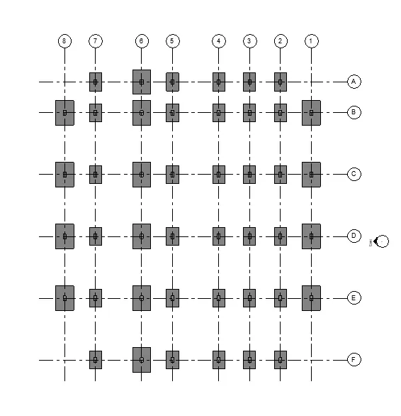
- Form the structural tab select column under structural panel
- Form the property browser select appropriate column and edit the size of required column
- Placed the column manually according to the size of footing
- Placed 3 different sizes of column
-
STEP 5) CREATED BEAM CONNECTED TO THE COLUMN
- Open ground level form project browser under the structural plans
- Form the structural tab select beam under structural panel
- Form the property browser select appropriate beam and edit the size of beam as 9”x18”
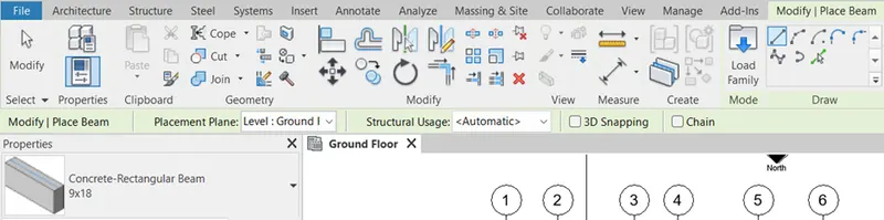
- By using line tool connect beam between two columns on mid-point
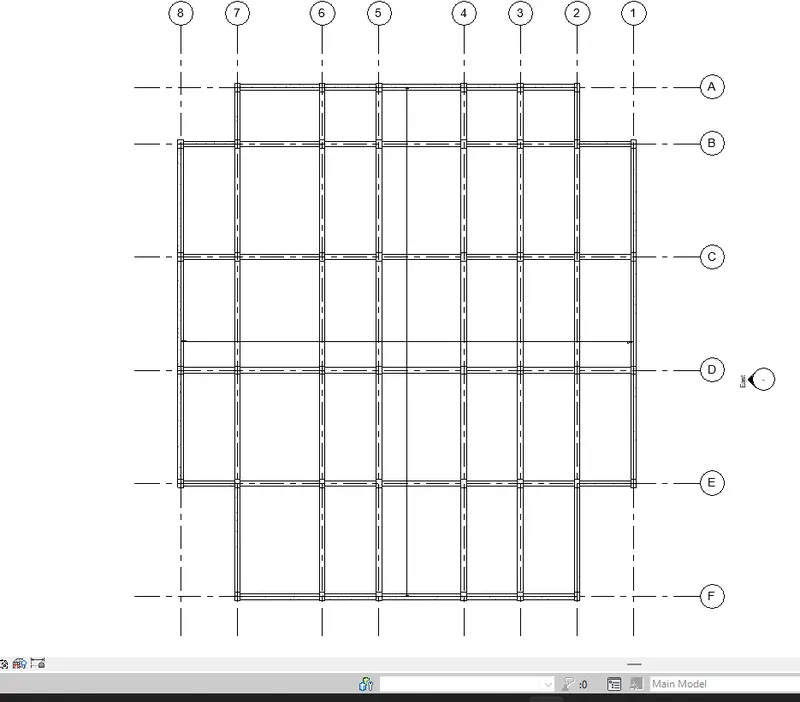
-
STEP 6) CREATED ROOF
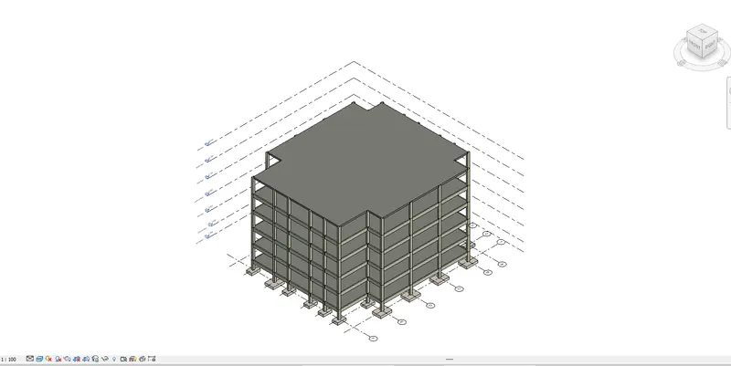
- In the ground floor plan created slab
- Go to structural tab select structural floor
- select appropriate material of slab from properties browser
- by using line tool draw the line periphery of the plan then finish
- similarly, copy the created floor for other levels
- similarly slab created for head room of staircase and lift
-
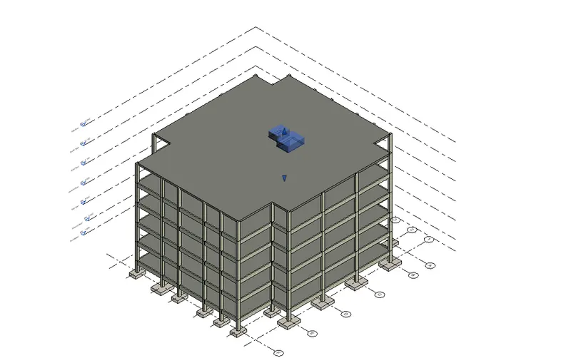
STEP 7) CREATED SHAFT OPENING FOR ELEVATOR AND STAIRS
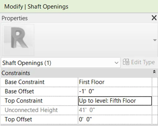
- In the first-floor plan created shaft
- Go to structural tab select shaft from opening panel
- By using line tool draw line on the staircase and elevator location
- After finish shaft opening change top constraint up to fifth floor
-
RESULT:
By following above procedure we have created foundation, column, beam, roof framing, floors and opening for stairs and elevator then save the model as central flie
) Using the architectural model, include the following components based on the type of structure selected
a. Wall Layout with appropriate material and finishing
b. Exterior façade with fancy finish
c. Interior partition walls to size rooms
d. Components to add details to a room ( Desk, Chair, Lighting, Plumbing fixtures)
e. Add components such as stairs Elevators
f. Have at-least one side of the building with curtain walls and glass panels
g. Include interior and exterior lighting fixtures
h. Place proper topographic components from outside ( Trees, Parking, Plants) to add details to the modelAIM:
By using architectural template to create the residential building according to the structural model
INTRODUCTION:
In the model we created architectural plan for residential multi-unit apartment according to structural plan
PROCEDURE:
STEP 1) CREATE MODEL FOR PROJECT
- Open Revit software
- Select new model from Revit home interface
- Choose architectural template>OK
- From the file tab save the model with appropriate name
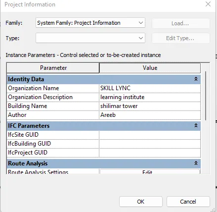
STEP 2) CREATE INFORMARTION FOR PROJECT
- For completing the project information
- Open MANAGE tab
- Select Project Information

- Project information dialog box will show
- Provide the basic information of current project
- Like identify data and other
STEP 3) CREATED ARCHITECTURAL WALL
- Create levels for architectural model based on structural modal and rename arcordingly
- Come to the ground floor level
- Create exterior wall with appropriate size and material
- Copy the walls upto forth floor level
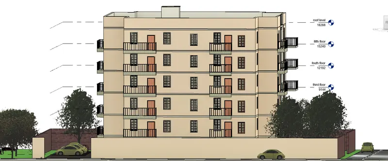
STEP 4) CREATED EXTERIOR FAÇADE
- In the fisrt floor plan add curtain wall and fancy window as a exterior façade
- Using copy tool to paste aligned with selected levels
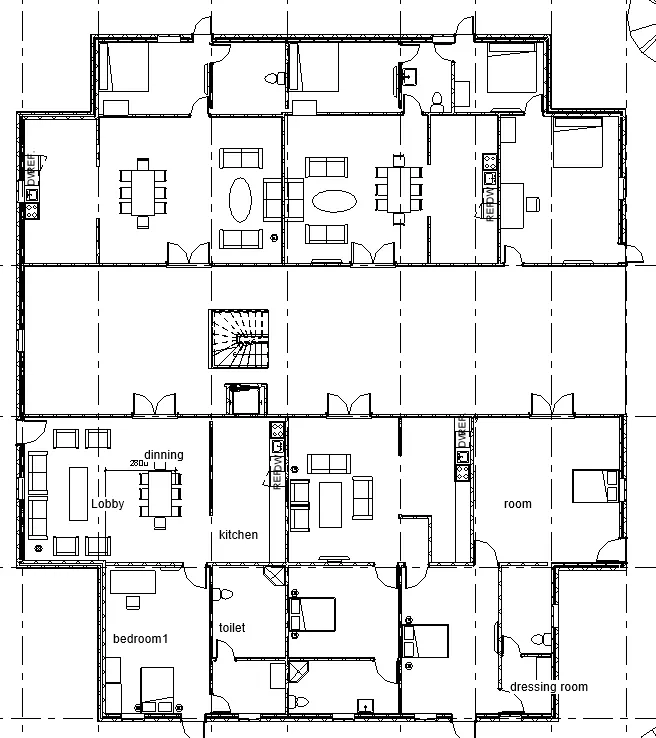
STEP 5) CREATED INTERIOR PARTION WALL
- Select appropriate wall for partition the rooms
- Placed doors accordingly
- Copy the interior partition wall and doors to other level
-
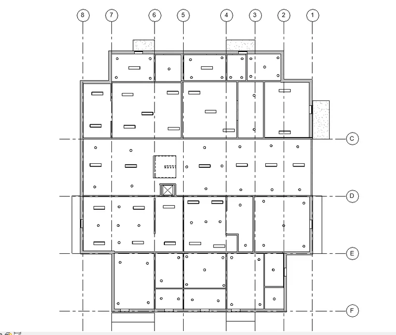
STEP 6) ADD COMPONENT
- First created floor in first floor plan
- As I selected Residential building, added component in the first-floor plan
- Components like bed, chair, table, cupboard, desk, sofa set, dining table, TV, Kitchen equipment’s, Toilet essentials, etc.
- Create ceiling in the first-floor ceiling plan
- Added lights in ceiling
- Copy all the components in other levels accordingly
-
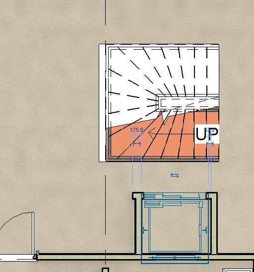
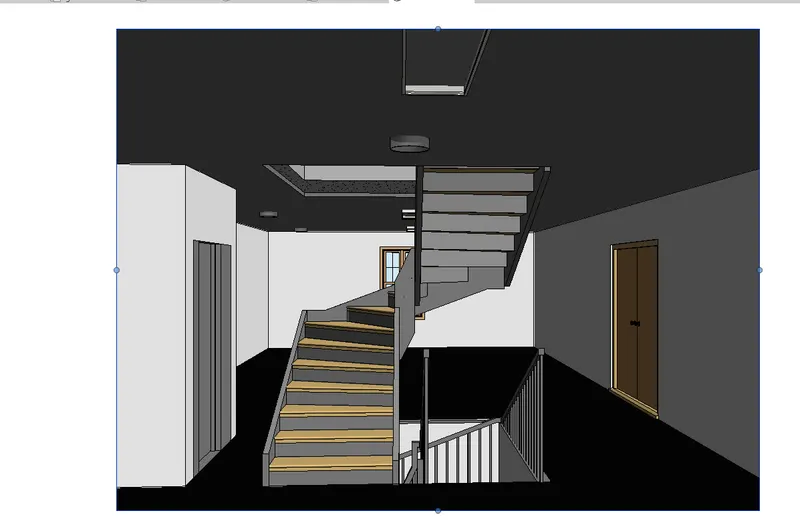
STEP 7) CREATE STAIRS AND ELEVATORS
- In the first-floor plan provide opening for stair and elevator with the help of shaft opening tool
- go to architectural tab select stair from the circulation panel
- create stair as per required location and elevator as well
- copy the same on all other floors
-
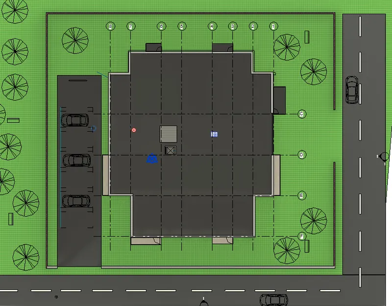
STEP 8) CREATE SITE TOPOGRAPHY
- In the site level plan
- Go to massing and site select toposurface
- Place the point for toposurface and finish
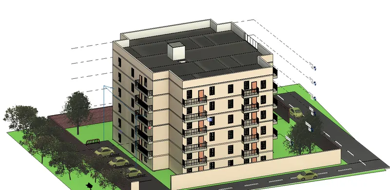
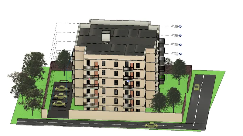
- Add site component such as Tree, Parking, Bench, Trash Bins, Exterior Lights, Cars, Road etc
RESULT:
As followed above procedure, have created architectural plan for Residential Building with the internal and external details
-
5) Provide a set of drawings in an architectural and structural model to list the following details with categories and appropriate sheet templates included
a. Floor Plans with Annotations
b. Elevations
c. SectionsAIM:
Provide an appropriate sheet of drawing for architectural and structural model
INTRODUCTION:
In the architectural and structural model, we created sheet for floor plans, elevations and sections
PROCEDURE:
STEP 1) CREATE SHEET
- Go to view tab, select sheet from sheet composition
- Choose appropriate sheet
- Modify the sheet detail accordingly
STEP 2) ADD ARCHITECTURAL DRAWING IN SHEET
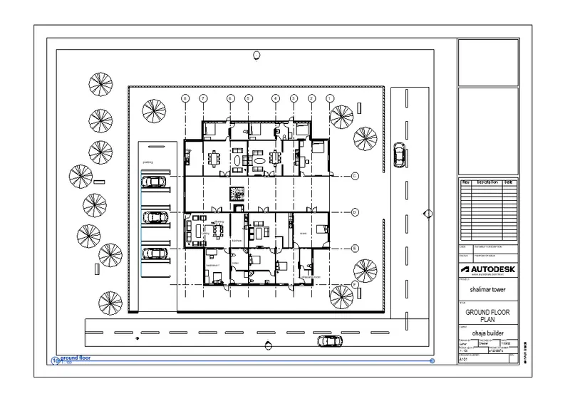
- Select the ground floor plan from architecture model
- Drag and drop the model to the sheet
- Follow same for all other models
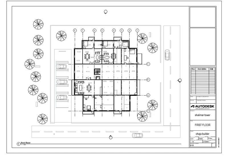
Architectural Typical Floor Plan:
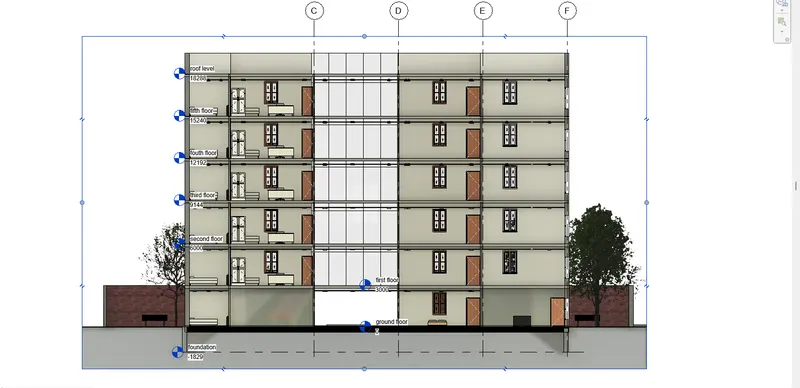
- Architectural section view
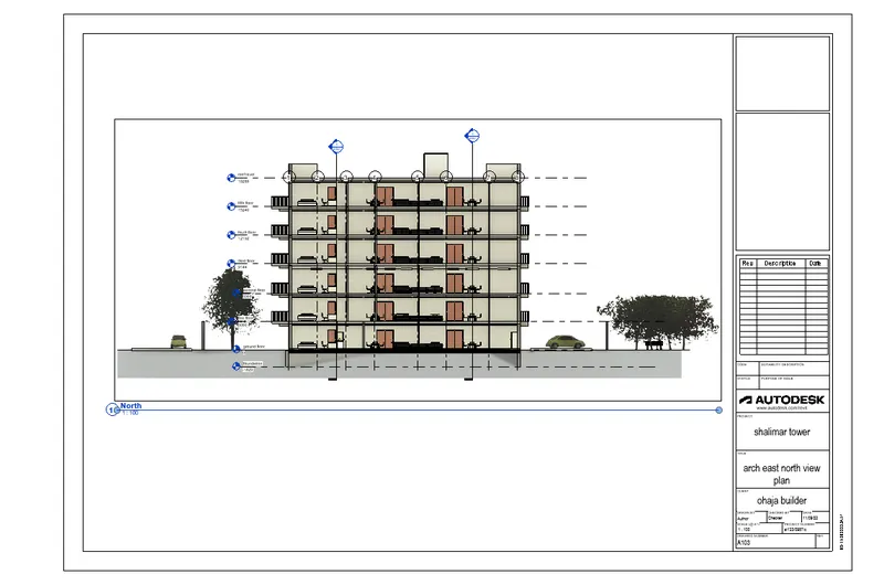
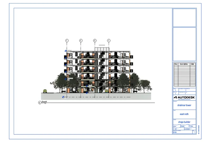
-
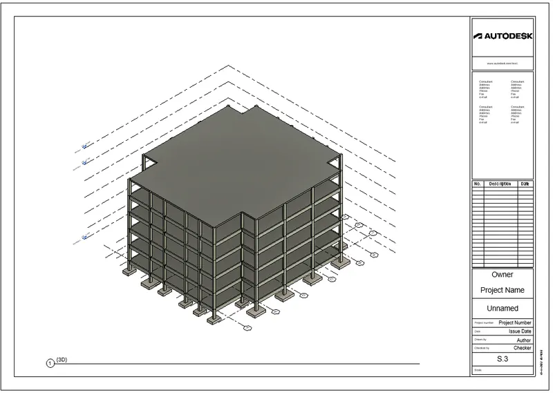
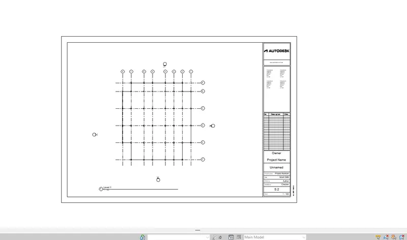
STEP 2) ADD STRUCTURAL DRAWING IN SHEET
- Select the ground floor plan from structural model
- Drag and drop the model to the sheet
- Follow same for all other models
6) Using the Rendering settings, Render images of the 3D model produced and include the rendered images to the drawing sheets
a. Rendering from interior rooms
b. Rendering from out showing topographic features
c. Rendering through structural framingAIM:
Rendering the image of the 3D model by using Render settings
INTRODUCTION:
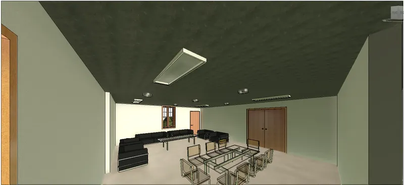
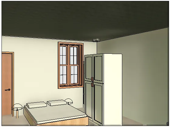
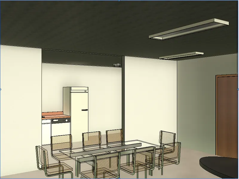
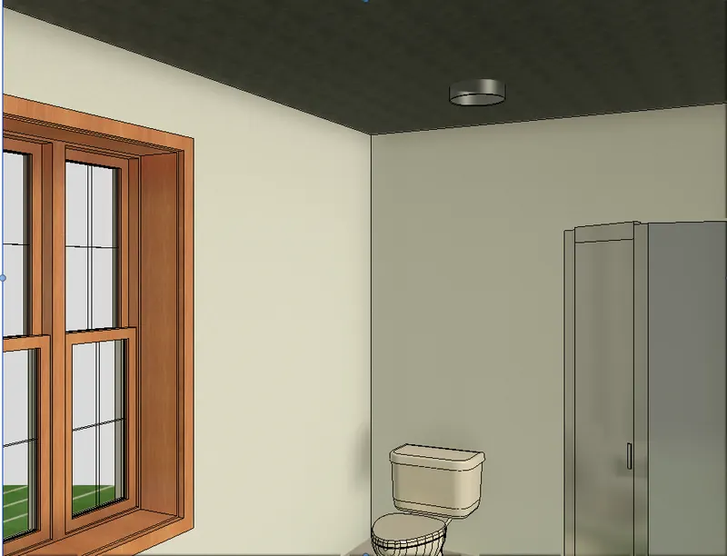
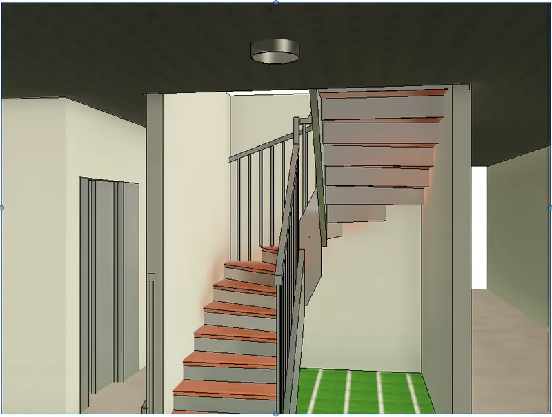
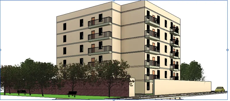
Rendering the 3D models by using render setting and included the rendered image to the sheet such as interior rooms, topographic surface and structural framing
PROCEDURE:
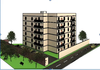
STEP 1) CREATE CAMERA FOR RENDER
- Go to view tab, drop down the 3D view
- Click on Camera and place accordingly for rendering
- Set appropriate view in camera
- Change view as realistic and rename the view
- Follow the same step for create the other views
-
STEP 2) CREATE RENDERING
- Open a specific camera view from the 3D view
- Go to view tab and select render
- In the rendering dialog box change the quality of rendering image as per choice
- modify the output settings and Lighting Scheme
- click on Render button to start the rendering
- once rendering completed save the rendered view accordingly
-
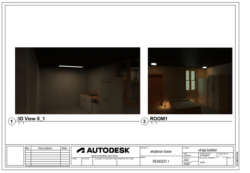
Rendered Interior Bed Rooms and kitchen View:
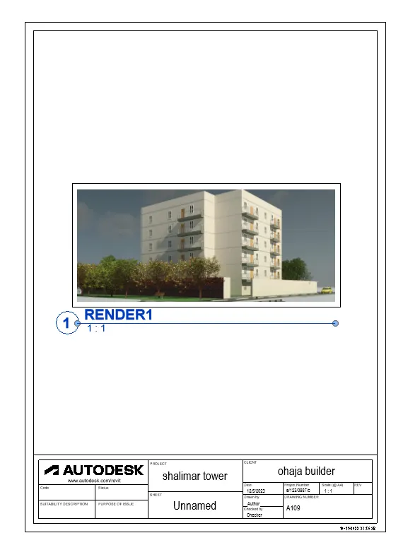
- Rendered Exterior Back View:
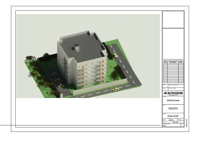
- Rendered Exterior Eagle Eye View:
- Rendered Interior Drawing Room View:
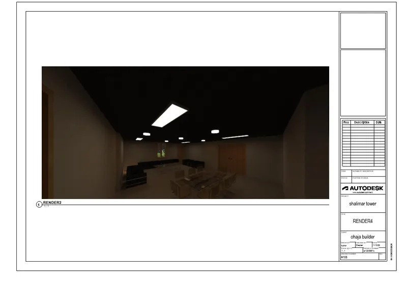
- Rendered Interior Toilet View:
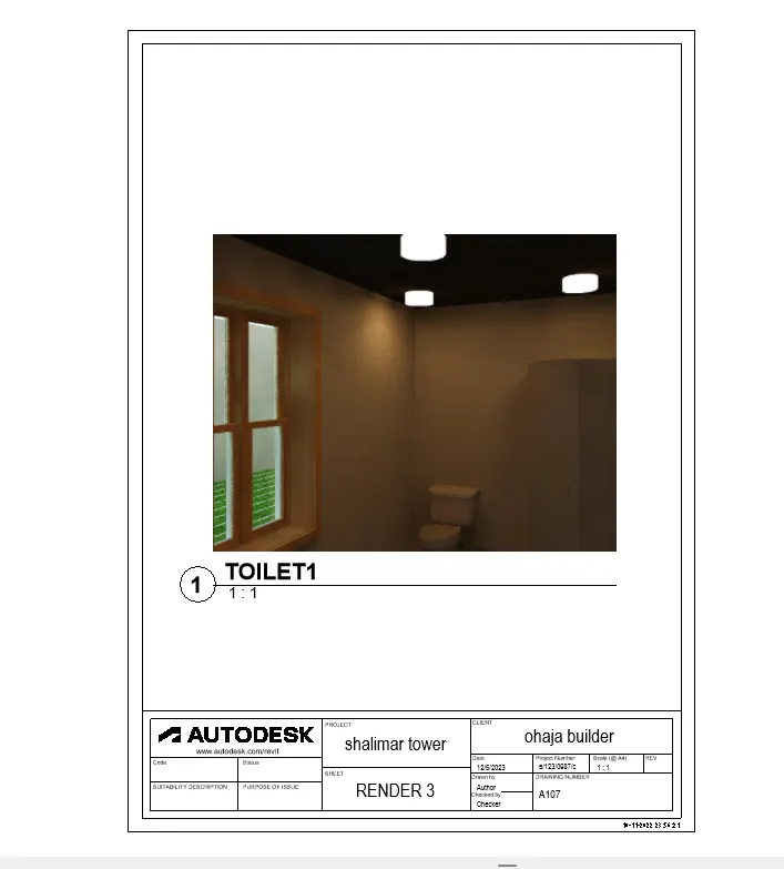 View:
View:-
7) Print the set of drawing sheets created and submit the drawings from the architecture and structure model
AIM:
Print the drawing sheet for Architectural and structural plan
INTRODUCTION:
For submitting the Drawing, printing all the created sheet of drawing
PROCEDURE:
STEP 1) PRINT THE DRAWING SHEET
- Open the structural and Architectural drawing sheet one by one for printing
- Press CTRL+P for print the sheet
- Provide necessary changes in print dialog box and click OK
- Take a print of the sheet or save as a PDF
- Follow the same step to print the copy of all the sheets
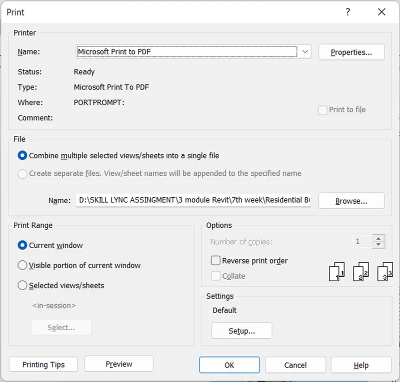
RESULT:
After following above procedure, created the printed copy of drawing sheet as shown, followed the same procedure for all the drawing sheet