Creating Architectural and Structural model with 3D rendering using REVIT
Creating Architectural and Structural models with 3D rendering using REVIT
AIM -
TO STUDY THE USAGE OF COLLABORATION TOOLS IN REVIT
INTRODUCTION -
Autodesk Revit is a building information modeling software tool for architects, landscape architects, structural engineers, mechanical, electrical, and plumbing (MEP) engineers, designers, and contractors. The original software was developed by Charles River Software, founded in 1997, renamed Revit Technology Corporation in 2000, and acquired by Autodesk in 2002. The software allows users to design a building and structure and its components in 3D, annotate the model with 2D drafting elements, and access building information from the building model's database. Revit is 4D building information modeling capable with tools to plan and track various stages in the building's lifecycle, from concept to construction and later maintenance and/or demolition
Autodesk Revit is a Building Information Modeling (BIM) tool, which can be used by more than one person working on a new project. This is an important feature in collaboration within a project, between projects, and with other users, firms, and disciplines.
Collaboration Tools guide is to enable students, who have a basic knowledge of Autodesk Revit, to increase their productivity while working with other people on a team, either in the same firm or other firms as well as with other disciplines. It also covers linking Autodesk Revit files and linking or importing other CAD files. Practices are available for each of the primary disciplines covered by Autodesk Revit: architecture, MEP, and structure.
TASK 1) Select the type of structure you want to build from one of the three below:
a. Multi-Unit Residential Apartment
b. Office Buildings
c. School
I CHOOSE A OFFICE BUILDING FOR THIS PROJECT
TASK 2) Assume reasonable assumptions for geographic and location details for your project modeling. Based on assumptions and type of structure selected identify the modeling requirements from NBC
The office building is planned to be constructed in DELHI.
Modeling requirements as per NBC
Since my building is an office building.
The open space around the building shall not be less than 4.5m.
Considering the type of construction as type 2 construction, the FAR value for the business building shall be taken as 2.9. The plot size is taken as 53mx52m i.e, 2750m2 and the individual floor area is 1700m2. Hence, the FAR value obtained is 2.14 which is within the prescribed limits as per NBC.
The width of the road abutting the building is taken as 30'.
The maximum height of the building shall not exceed 1.5 times the width of the road abutting plus the front open space.
The building will consist of 7 floors each floor having a floor height of 15'. Hence, the entire floor height will be 90', which is within the limits prescribed by NBC.
TASK 3) Using the structural model, include the following components based on the type of structure selected
a. Foundation – Isolated / Wall/Matt Foundation
b. Columns
c. Beams Connected to Columns
d. Roof Framing/ Truss
e. Floor / Decks
f. Floor Openings for Elevators and Stairs
PROCEDURE -
STEP 1 -
- Go to the Window search box to open a Revit workspace.
- In the window search bar type REVIT, and the icon of the Revit application will show on the screen
- Click on the icon of REVIT, the application of Revit will open and the user interface of Revit will show on the screen.
- Click on the existing project created Last week
- We have created a structural and architectural plan and synchronized it with the central model.
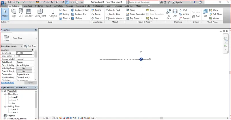
- Open an architectural model and clear a grids
STEP 2 -
- Go to the Window search box to open a Revit workspace.
- In the window search bar type REVIT, and the icon of the Revit application will show on the screen
- Click on the icon of REVIT, the application of Revit will open and the user interface of Revit will show on the screen.
- Click on the existing project created Last week
- We have created a structural and architectural plan and synchronized it with the central model.
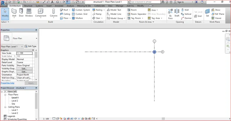
- Open a structural model and clear a grids
STEP 3 -
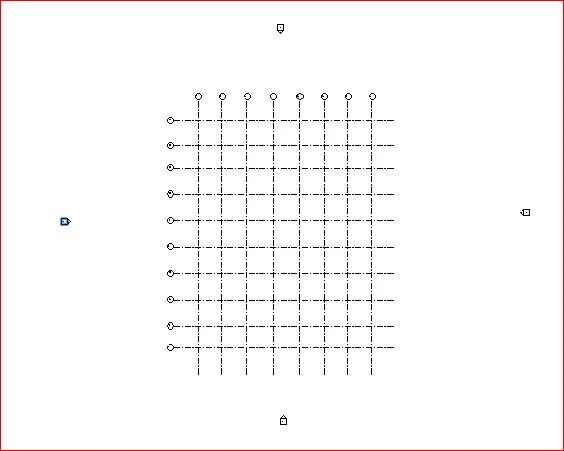
- Go to the architectural tab and select a grid
- Draw a grid according to our plan as shown in the image.
STEP 4 -
- Go to the architectural tab and select a LEVEL
- Draw a level according to our plan as shown in the image.
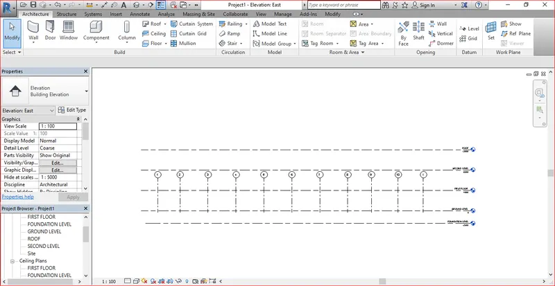
STEP 5 -
- Go to the structural tab and select an ISOLATED as shown in the image.
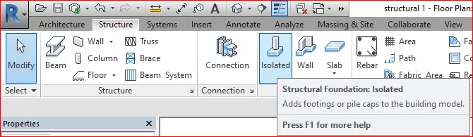
STEP 6 -
- Select a grid and Press ENTER the footing is placed at the grid go to the 3d view we can see all the footing as shown in the image.
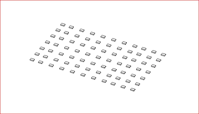
STEP 7 -
- Go to the structural tab and select the column as shown in the image.
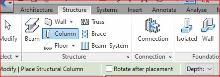
STEP 8 -
- Select the grid and press ENTER and go to the 3d view to see the column
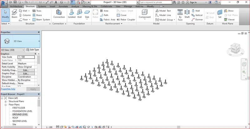
STEP 9 -
- Select the column from the structural tab and select the grids and specify the connection as roof and press ENTER.
- the column is created.
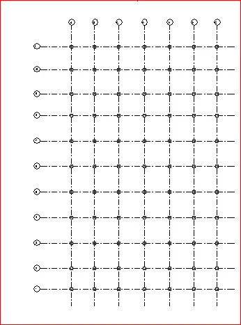
STEP 10 -
- Go to the 3d view to see the column in the isometric view.
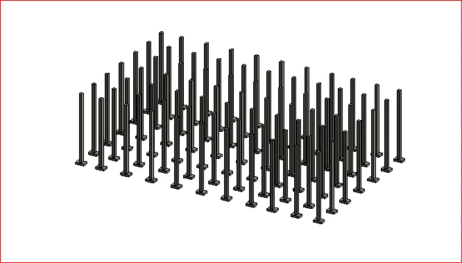
STEP 11 -
- Go to the structural tab and select the beam
- Click on the grid and select all the grids and press ENTER.
- the beam is created.
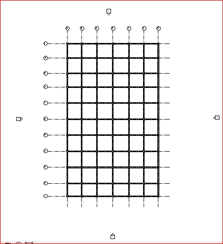
STEP 12 -
- Go to the 3d view to see the BEAM in the isometric view
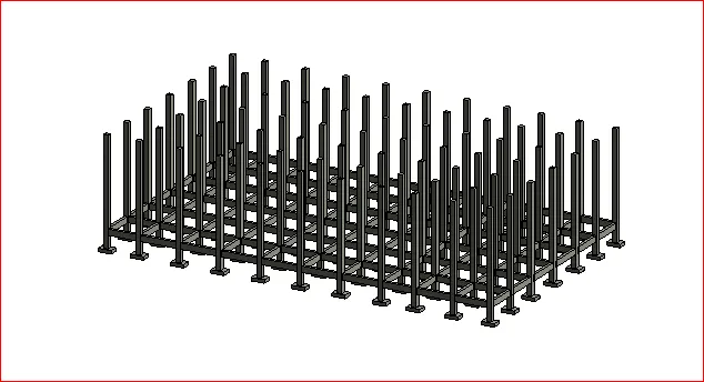
STEP 13 -
- Copy all the beam and select them to the clipboard and paste it to the assigned selected level as select all the level
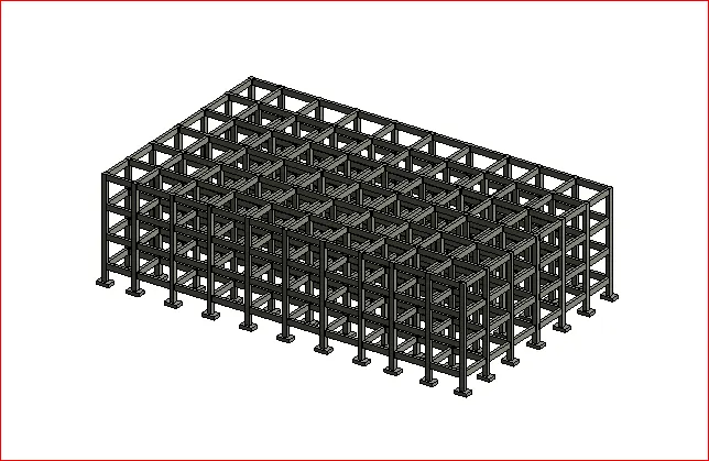
STEP 14 -
- Go to the ground floor and select the floor from the structural tab
- Now go to the modify toolbar and select the rectangular
- And draw a rectangle for the floor as shown in the image.
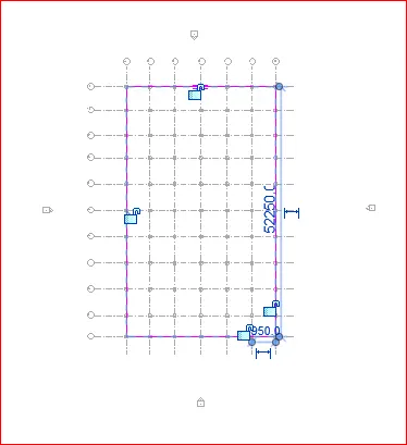
STEP 15 -
- Floor is created at the ground level
- Go to the 3d view to see the BEAM in the isometric view
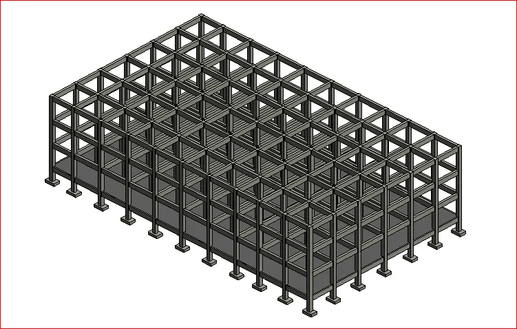
STEP 16 -
- Copy all the FLOOR and select them to the clipboard and paste it to the assigned selected level as select all the levels.
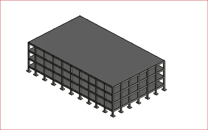
TASK 4) Using the architectural model, include the following components based on the type of structure selected
a. Wall Layout with appropriate material and finishing
- Go to the Window search box to open a Revit workspace.
- In the window search bar type REVIT, and the icon of the Revit application will show on the screen
- Click on the icon of REVIT, the application of Revit will open and the user interface of Revit will show on the screen.
- Click on the existing project created in week 2 challenges
- Go to the architectural tab and select the wall and draw the boundary of the wall
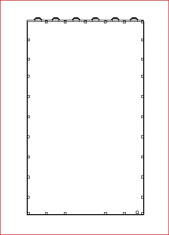
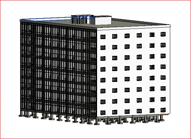
b. Exterior façade with fancy finish
- 3d view of the wall created the last the step
- One side is a brick wall and the other 3d side are a certain wall.
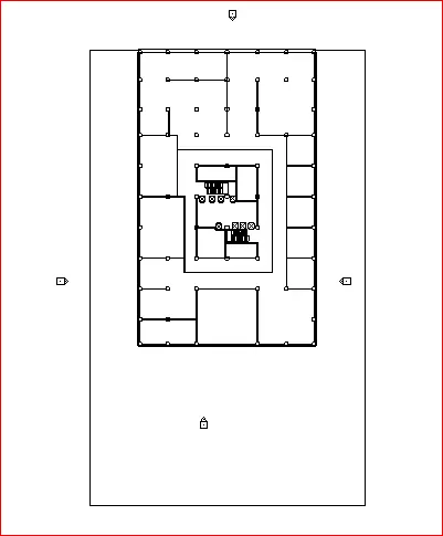
c. Interior partition walls to size rooms
- Select the wall from the architectural tab and select the interior wall from the properties dialog box
- and create an interior wall.
d. Components to add details to a room ( Desk, Chair, Lighting, Plumbing fixtures)
- All the components are placed in a room such as a Desk, Chair, and Lighting.
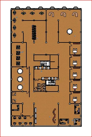
e. Add components such as stairs Elevators
- Stair and lift are created as shown in the image.
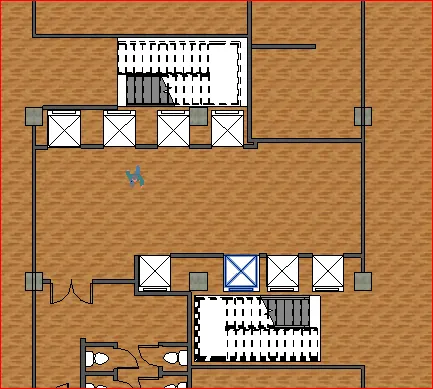
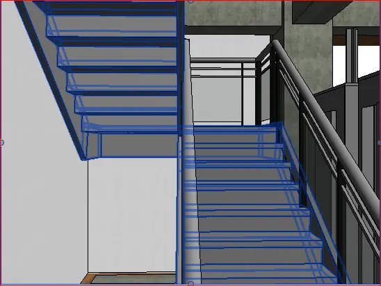
- 3d view of stairs.
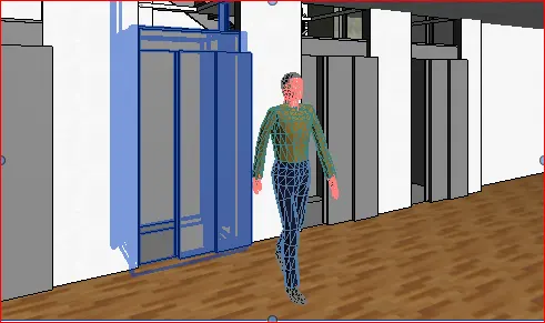
- 3d view of LIFT.
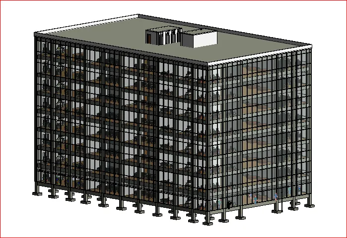
f. Have at least one side of the building with curtain walls and glass panels
- Wall of the building with the curtain wall and glass panels.
g. Include interior and exterior lighting fixtures
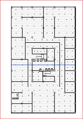
- Interior lightsise placed as shown in the image.
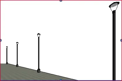
- Exterior lights are placed as showninn the image.
h. Place proper topographic components from outside ( Trees, Parking, Plants) to add details to the model
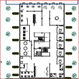
- All the topographic components from outside places such as tree parking and plants
TASK 5) Provide a set of drawings in an architectural and structural model to list the following details with categories and appropriate sheet templates included
a. Floor Plans with Annotations
b. Elevations
c. Sections
PROCEDURE -
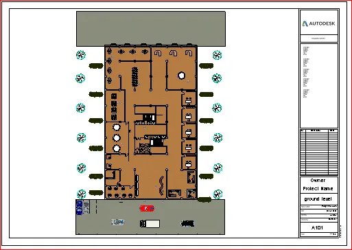
- Go to Ribbon > View > Sheet to create a sheet.
- A new dialog box will open as the name NEW SHEET
- Select an A0 metric and click on OK
- A sheet will be created on the screen as shown.
- Go to Ribbon > View > View
- A dialog box will open as the name VIEWS
- Select the file to add to the sheet
- Here, I choose a FLOOR PLAN GROUND LEVEL
- and Click on add view to the sheet.
- The view is added to the sheet as shown in the picture
FLOOR PLAN
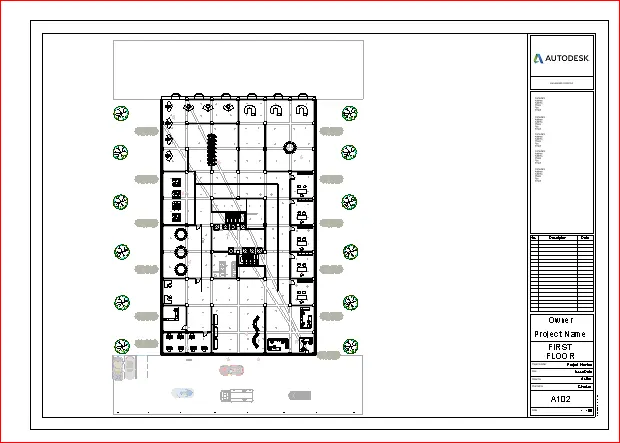
FIRST TO SEVENTH LEVEL PLAN
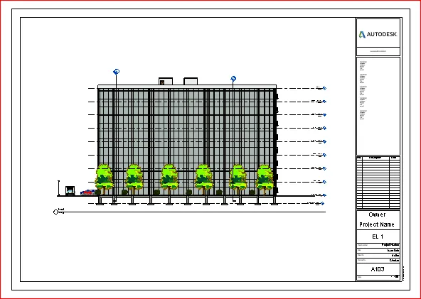
EAST ELEVATION
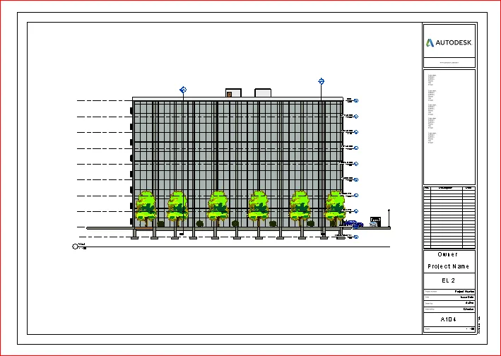
WEST ELEVATION
NORTH ELEVATION
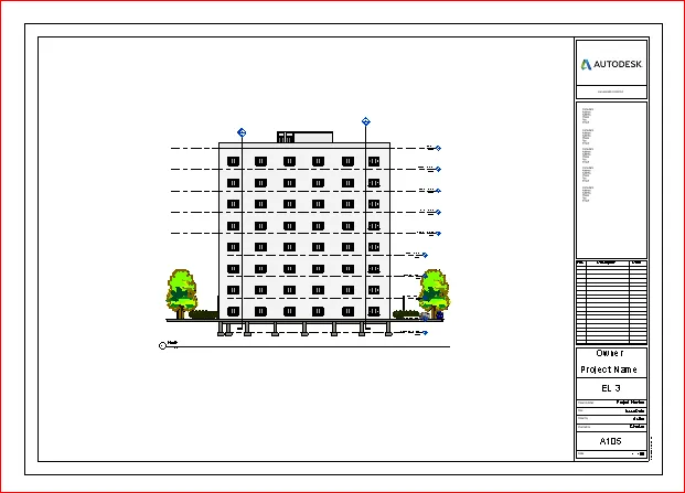
SOUTH ELEVATION
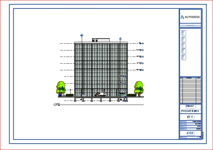
SECTION 1 - 1'
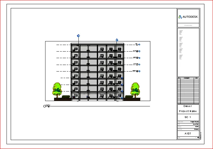
SECTION 2 - 2'
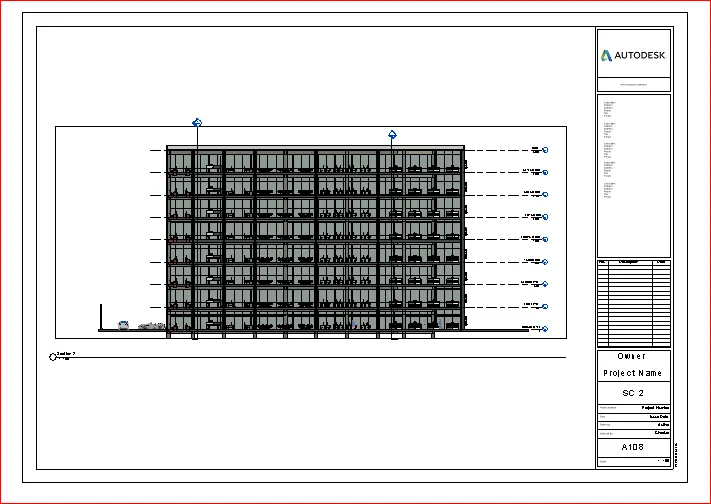
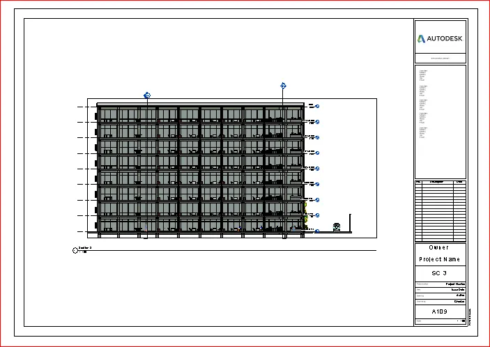
SECTION 3 - 3'
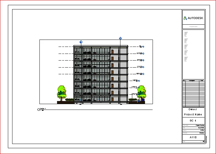
SECTION 4 - 4'
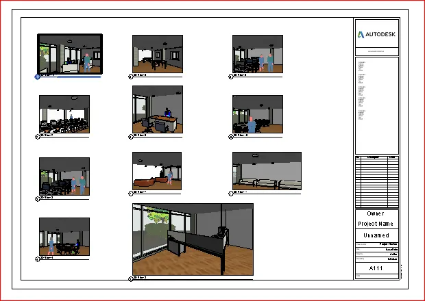
TASK 6) Using the Rendering settings, Render images of the 3D model produced and include the rendered images in the drawing sheets
a. Rendering from interior rooms
b. Rendering from out showing topographic features
c. Rendering through structural framing
PROCEDURE -
- Go to theethew and click on the 3d view drop down and select a camera now place your camera to see a 3d view from the inside of the building.
Office 1
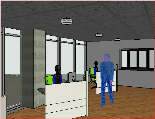
Office 2
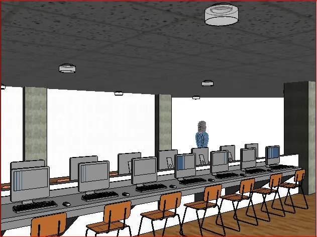
Office 3
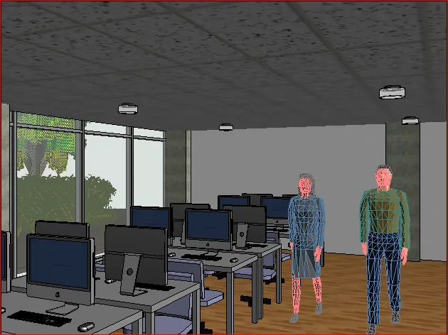
Office 4
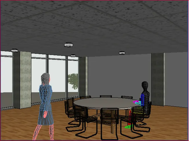
Office 5
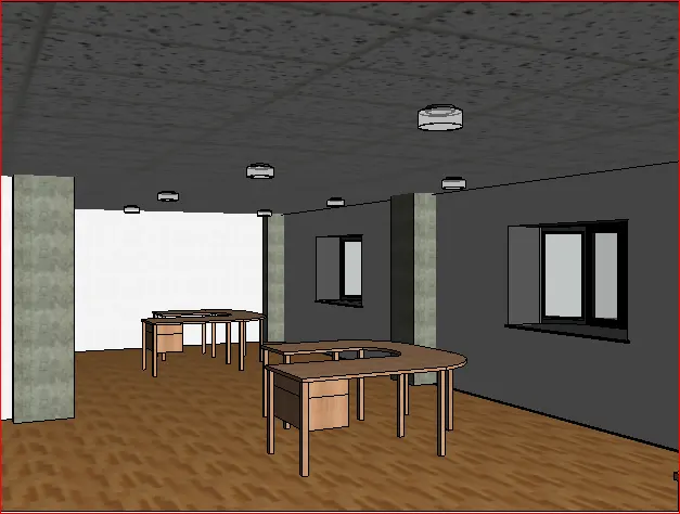
Office 6
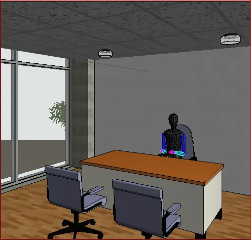
RECEPTION AREA
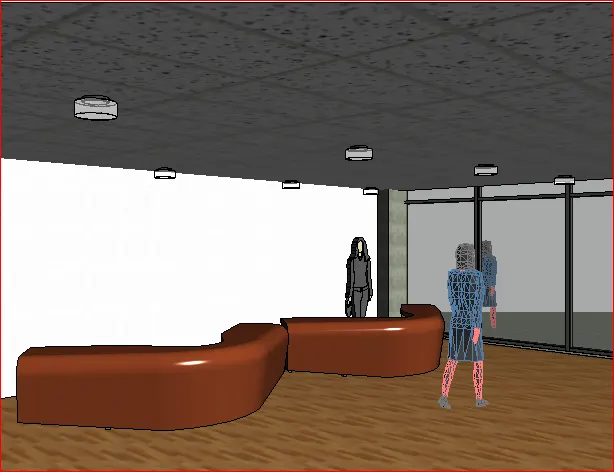
Office 7
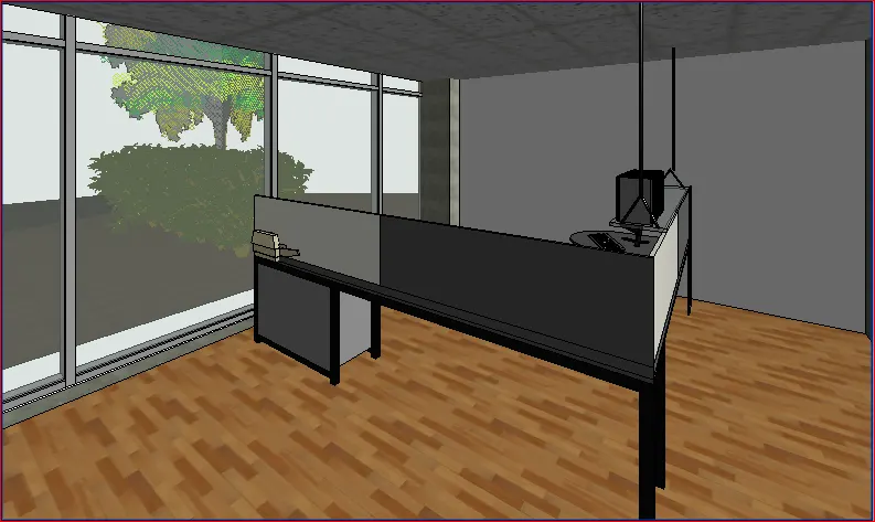
Office 8
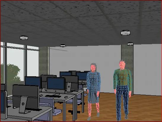
Office 9
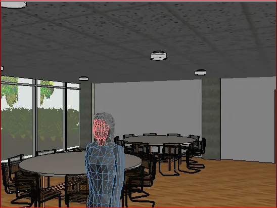
Office 10
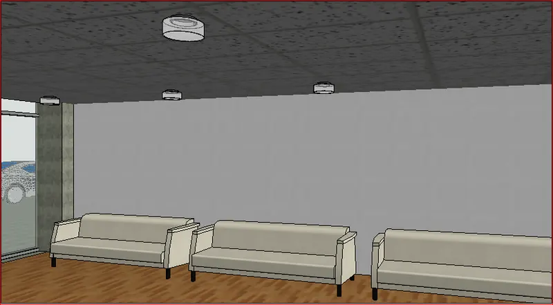
Office 11
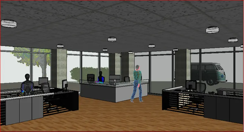
Office 12
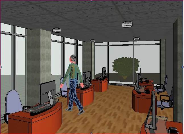
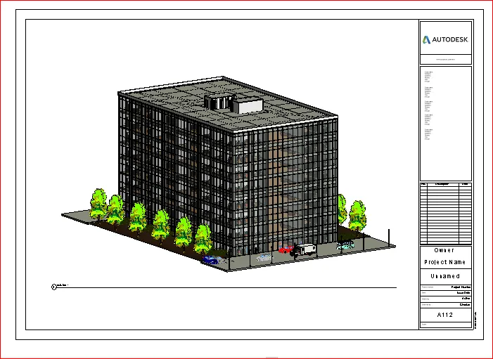
BUILDING VIEW 1
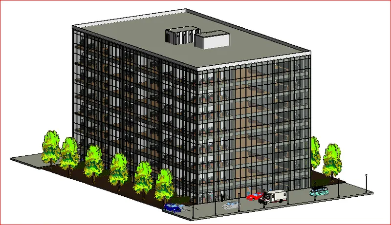
BUILDING VIEW 2
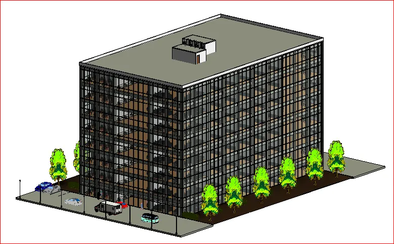
BUILDING VIEW 3
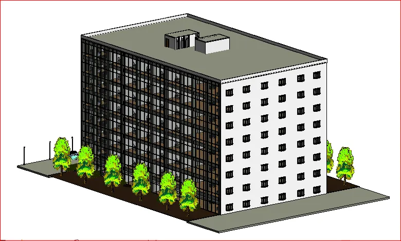
BUILDING VIEW 4
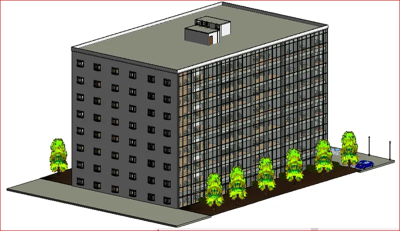
RESULT -
TASK 7) Print the set of drawing sheets created and submit the drawings from the architecture and structure model
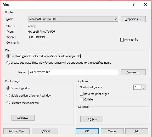
The different drawing templates can be printed. This can be done by going to the file menu in the top left corner of the Revit window and in that choose to print, then this window appears.